CIRTEN
CONSORZIO INTERUNIVERSITARIO
PER LA RICERCA TECNOLOGICA NUCLEARE
UNIVERSITA’DIPALERMO
DIPARTIMENTO DI INGEGNERIA NUCLEARE
TRACE INPUT MODEL FOR SPES3 FACILITY
F. Castiglia, P. Chiovaro, M. Ciofalo, M. Di Liberto, P.A. Di Maio,
I. Di Piazza, M. Giardina, F. Mascari, G. Morana, G. Vella
CIRTEN-UNIPA RL-1208/2010
Palermo, Luglio 2010
Lavoro svolto in esecuzione della linea progettuale LP2-B dell’AdP ENEA MSE del 21/06/07, Tema 5.2.5.8 – “Nuovo Nucleare da Fissione”
ABBREVIATION
ADS Automatic Depressurization System ADS-ST ADS Single Train
BAF Bottom of Active Fuel
CRDM Control Rod Driven Mechanism CV Containment Vessel
DC Downcomer
DEG Double Ended Guillotine DOE U.S Department Of Energy DW Dry Well
DVI Direct Vessel Injection EBT Emergency Boration Tank
EHRS Emergency Heat Removal System FDA Final Design Approval
FL Feed Line FW Feed Water
HX Heat Exchanger
IRIS International Reactor Innovative and Secure LGMS Long Term Gravity Make-up System LOCA Loss Of Coolant Accident
LP Lower Plenum LWR Light Water Reactor MFIV Main Feed Isolation Valve MSIV Main Steam Isolation Valve NRC U.S. Nuclear Regulatory Commission PCC Passive Containment Cooling PRZ Pressurizer
PSS Pressure Suppression System PWR Pressurized Water Reactor QT Quench Tank
RC Reactor Cavity
RCCA Rod Cluster Control Assembly RCS Reactor Coolant System
RELAP5 Reactor Excursion and Leak Analysis Program RPV Reactor Pressure Vessel
RWST Refueling Water Storage Tank SG Steam generator
SL Steam Line
SPES Simulatore Per Esperienze di Sicurezza
SCOPE
The primary goal of this document is to describe the SPES3 facility nodalization for the TRACE V5.0 Patch Release 1 code, developed to make a comparison between the SPES3-RELAP5 and SPES3-TRACE calculated results, as support to the design review of the primary, secondary and containment systems of the experimental plant.
CHAPTER 1
DESCRIPTION OF IRIS REACTOR
1-1
INTRODUCTION
The International Reactor Innovative and Secure (IRIS) is a modular, medium size Advanced Light Water Reactor that provides a viable bridge to Generation IV reactors and satisfies the Global Nuclear Energy Partnership requirements for grid-appropriate Nuclear Power Plants. Based on a safety-by-design philosophy, the IRIS integral configuration represents the advanced engineering solution of the latest LWR technology. This allows the reactor commercialisation without the construction of a demonstration prototype, once the FDA is obtained by NRC. The IRIS design was conceived to satisfy the DOE requirements for the new generation reactors, that is, improved proliferation resistance, enhanced safety, improved economics and reduced waste. IRIS is a small-medium size (1000 MWth) PWR with an integral configuration, suitable for modular deployment, Fig. 1-1.
1-2. RPV
DESCRIPTION
The RPV hosts all the main RCS components: Core, PRZ, spool-type reactor coolant pumps, SGs and Control Rod Drive Mechanism. Eight once-through helical coil SGs are located around the riser and a pump is installed axially on top of each SG. The riser is defined by the extension of the core barrel. The “inverted hat” PRZ occupies the RPV upper head. The water flow path is from bottom to top through the core and riser, then the circulation reverses and water is pushed downward by the immersed pumps through the SG tubes. At the SG outlet, the flow path goes along the annular DC region outside the core to the LP and then back into the core. The RCS integral layout leads to a RPV diameter of 6.2 m, larger than a conventional PWR, with a total height of about 22 m. A compact spherical steel containment, 25 m in diameter, is part of the IRIS safety approach and is directly involved, through a coupled dynamic behavior, in the passive mitigation strategy that enhances the safety and reliability of IRIS.
Figure 1-1. IRIS layout (Carelli,M.,2009). 1-2-1. Reactor coolant pumps
The spool type pump is located entirely within the reactor vessel; only small penetrations for the electrical power cables are required. High temperature motor windings and bearing materials are being developed to eliminate any need for cooling water and the associated piping penetrations through the RPV. The spool pump geometric configuration provides high inertia-coastdown and high run-out flow capability that will contribute to mitigate the consequences of possible Loss-Of-Flow Accidents.
1-2-2. Steam generators
The IRIS SGs employ a once-through, helical-coil tube bundle design with the primary fluid outside the tubes. Eight steam generator modules are located in the annular space between the core
barrel (outside diameter 2.85 m) and the reactor vessel (inside diameter 6.2 m). Each IRIS SG module consists of a central inner column which supports the tubes, the lower feed water and upper steam headers, a central inner column to support them, and an outer wrapper. The enveloping outer diameter of the tube bundle is 1.64 m. Each SG has 656 tubes, and the tubes and headers are designed for the full external RCS pressure. The tubes are connected to the vertical sides of the lower feedwater header and the upper steam header. The SG is supported from the RPV wall and the headers are bolted to the vessel from the inside of the feed inlet and steam outlet pipes. A double gasket, with a monitor leak-off, provides the pressure boundary between the primary coolant and the secondary side feed water inlet and steam outlet penetrations in the reactor vessel.
1-2-3. PRZ
The IRIS pressurizer is integrated into the upper head of the reactor vessel. The pressurizer region is defined by an insulated, inverted top-hat structure that divides the circulating reactor coolant flow path from the saturated pressurizer water. This structure includes a closed cell insulation to minimize the heat transfer between the hotter pressurizer fluid and the subcooled water in the primary water circulating flow path.
By utilizing the upper head region of the reactor vessel, the IRIS pressurizer provides a very large water and steam volume, as compared to plants with a traditional, separate, pressurizer vessel. The IRIS pressurizer has a total volume of ~70 m3, which includes a steam volume of ~50 m3. This large steam volume to power ratio contributes to the fact that IRIS does not require the use of a pressurizer spray function to prevent the pressurizer safety valves from lifting for any design basis heat-up transients.
1-3. IRIS
SAFETY
FEATURES
IRIS implements a passive emergency heat removal system made of four independent subsystems, each of which has an heat exchanger connected to a separate SG feed steam line. These heat exchangers are immersed in the RWST located outside the containment structure. The RWST water provides the heat sink to the environment for the EHRS heat exchangers.
The EHRS operates in natural circulation, removing heat from the primary system through the steam generators heat transfer surface, condensing the steam produced in the EHRS heat exchanger, transferring the heat to the RWST water, and returning the condensate back to the SG. The EHRS provides both the main post-LOCA depressurization (depressurization without loss of mass) of the primary system and the core cooling functions. The EHRS intervene at isolated reactor conditions. A PCC system allows limiting the CV pressure in case of EHRS unavailability.
1-3-1. Containment
description
The IRIS RPV is contained in a spherical, steel CV that is 25 m in diameter. The CV has a bolted and flanged closure head flange and bolting. The size reduction, combined with the spherical geometry, results in a design pressure capability at least three times higher than a typical loop reactor cylindrical containment, assuming the same metal thickness and stress level in the shell.
The containment vessel consists of different compartments, in particular the DW, the RC, the PSS and the LGMS (Fig. 1-2).
IRIS has two full-system pressure EBTs to provide a diverse means of reactor shutdown by delivering borated water to the RPV through the DVI lines. By their operation these tanks also provide a limited gravity feed makeup water to the primary system. EBT are connected to the DVI lines which inject water into the vessel from the LGMS and eventually back from the RC.
ADS from the PRZ steam space assists the EHRS in depressurizing the RPV when/if the RPV coolant inventory drops below a specific level. This ADS function ensures that the RPV and containment pressures are equalized in a timely manner, limiting the loss of coolant and thus preventing core uncover following postulated LOCAs even at low RPV elevations. An ADS dumps steam in a QT in case of need during normal operation.
1-4. IRIS
SAFETY-BY-DESIGN
APPROACH
The integral arrangement of the plant allows avoiding pressurized components like the SGs, outside the RPV and largely reduces the size and number of RPV penetrations. Large LOCAs are eliminated and the number of possible small LOCAs is reduced. The IRIS safety-by-design approach addresses small LOCA sequences by limiting and eventually stopping the loss of mass from the RPV rather than relaying on water injection by active or passive devices.
This is achieved by (i) a large coolant inventory in the RPV; (ii) a compact, high design pressure containment, thermodynamically coupled to the RPV which limits the blowdown by rapidly equalizing RPV and containment pressure during an accident; (iii) RPV depressurization by means of EHRS that remove the decay heat by condensing steam directly through the SGs.
A typical sequence of LOCA events can be summarized in the following phases: • blowdown: the RPV depressurises and looses mass to the containment;
• reactor trip, pump trip, reactor isolation and EHRS intervention, ADS actuation, the EHRS depressurizes the primary system without loss of mass while, if the ADS intervenes, it carries out the same function with loss of mass;
• the PSS limits the containment pressure, once the RPV-CV pressure equalization is reached and the blowdown phase ends;
• the RPV-CV coupled system is depressurised by the EHRS that condenses steam and has the capability of removing more than the decay heat;
• once the pressure inside the RPV becomes lower than the containment pressure, a reverse flow of a mixture of water and steam from the CV may occur through the break; • a long-term cooling phase follows the depressurization phase with the LGMS
REFERENCES
• Mario Carelli, Lawrence Conway, Milorad Dzodzo, AndreaMaioli, Luca Oriani, Gary Storrick, Bojan Petrovic, Andrea Achilli, Gustavo Cattadori, Cinzia Congiu, Roberta Ferri, Marco Ricotti, Davide Papini, Fosco Bianchi, ParideMeloni, StefanoMonti, Fabio Berra, Davor Grgic, Graydon Yoder, and Alessandro Alemberti. The SPES3 Experimental Facility Design for the IRIS Reactor Simulation. Hindawi Publishing Corporation Science and Technology of Nuclear Installations Volume 2009, Article ID 579430, 12 pages doi:10.1155/2009/579430.
• Mario D. Carelli , L.E. Conway a, L. Oriani a, B. Petrovi´c a, C.V. Lombardi b, M.E. Ricotti b, A.C.O. Barroso c, J.M. Collado d, L. Cinotti e, N.E. Todreas f, D. Grgi´c g, M.M. Moraes h, R.D. Boroughs i, H. Ninokata j, D.T. Ingersoll k, F. Oriolo. The design and safety features of the IRIS reactor. Nuclear Engineering and Design 230 (2004) 151–167.
• IAEA-TECDOC-1391. STATUS OF ADVANCED LIGHT WATER REACTOR DESIGNS IAEA,VIENNA, 2004 IAEA-TECDOC-1391 ISBN 92–0–104804–1 ISSN 1011–4289 © IAEA, 2004 Printed by the IAEA in Austria May 2004
CHAPTER 2
DESCRIPTION OF SPES3 EXPERIMENTAL FACILITY
2-1
INTRODUCTION
The SPES3 experimental programme is aimed at:
• Simulating the IRIS system thermal-hydraulic phenomena, the behavior of the passive safety systems and the interaction between the Reactor Vessel and the Containment following specified accidents (SBLOCA, Feedwater and Steam Line Breaks);
• Simulating the thermal-hydraulic behavior of selected key components of IRIS system design, such as the Steam Generators and the Condensers of the Emergency Heat Removal Systems;
• Providing detailed experimental results for the verification and validation of safety analysis codes.
2-2.
SPES3 EXPERIMENTAL FACILITY OVERVIEW
As a member of the IRIS consortium, ENEA coordinates the activities of design, construction and testing of a new Integral Test Facility, supported by the Italian Ministry of the Economic Development in the framework of a wider Italian R&D program on Nuclear Fission.
The SIET company is designing the SPES3 facility that will simulate accidental sequences for providing the needed experimental results to verify the general behavior of the system, to allow a code assessment process and to produce a reliable tool for the IRIS plant safety analyses.
A Phenomena Identification and Ranking Table and a Hierarchical Two-Tiered Scaling Analyses, evolved into a Fractional Scaling Analysis, led to identifying the main facility scaling parameters resulting in 1:100 volume scale, 1:1 elevation scale, prototypical fluid at plant pressure and temperature full conditions. SPES3 will provide experimental data based on a list of accidental transients required by NRC for the licensing process.
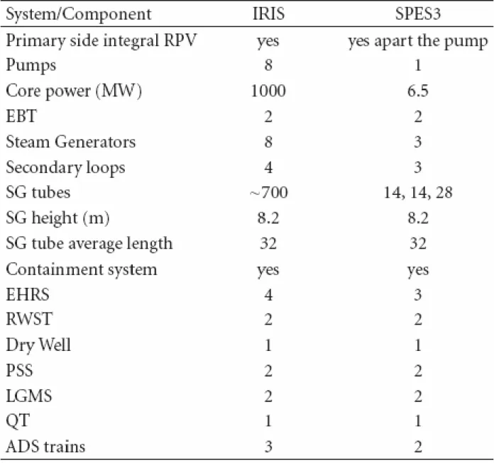
The code assessment on such data will guarantee the availability of reliable computational tools to perform the IRIS plant safety analyses for the Final Design Approval. Table 2-1 schematically shows a comparison between IRIS and SPES3.
Table 2-1. IRIS and SPES3 characteristic comparison
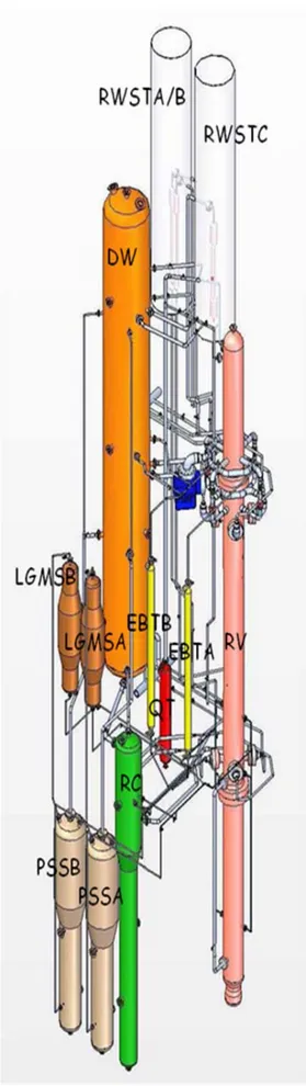
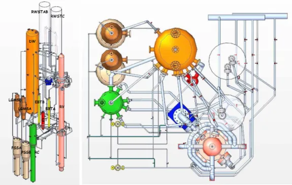
The SPES3-IRIS integral test facility, Fig. 2-1, will be built at SIET laboratories simulating, the primary, secondary, containment and safety systems typical of the IRIS reactor.
It will be suitable to perform both integral and separate effect tests and to investigate the thermal hydraulic interaction among the various systems.
The primary goal of testing on the SPES3-IRIS facility is to demonstrate the vessel to containment coupling as the main safety issue of IRIS plant in mitigating small LOCAs.
2-2-1.
Scaling PrincipleThe main facility scaling parameters resulting in 1:100 volume scale, 1:1 elevation scale, prototypical fluid at plant pressure and temperature full conditions.
The main parameters preserved by scaling are the fluid thermodynamic conditions (temperature, pressure, enthalpy), the vertical elevation, the power to flow ratio, the transit time of fluid, the heat flux, the pressure drops while the power to volume ratio is not preserved during the steady state and initial part of transients as scaled power should be 10 MW and only 6.5 MW are available at SIET, so the primary and secondary loop flow rates will therefore adjusted to maintain the steady state temperatures as in the IRIS plant.
Additional scaling criteria are applied to selected components design in order to better reproduce specific phenomena occurring in the IRIS plant during an accident.
2-3. SPES FACILITYDESCRIPTION
The primary system includes the RPV and internals with power channel and fuel bundle box, lower riser and RCCA, upper riser, PRZ, upper DC, SG zone, riser to DC connection check valves, lower DC, LP, core bypass, circulation pump, a portion of the DVI lines.
The secondary systems with steam lines and feed lines up to the MSIV and MFIV, includes three SGs simulating eight, with helical coils (loops A and B simulate two SGs each, loop C simulates four). The containment system includes the DW, the QT, the RC and DVI room, the PSS, the LGMS, the PCC, a portion of the DVI lines.
The containment tanks are connected by pipes. The safety system includes the EHRS located in the RWST, the EBT and the ADS. The no-safety systems includes the start-up FW. The primary system design pressure is 17.25 MPa and the design temperature is 353.5 °C (saturation at 17.25 MPa).
The secondary systems, up to the MSIV and MFIV, and emergency heat removal systems design pressure is 17.25 MPa and the design temperature is 353.5 °C .The containment design pressure is 2 MPa and the design temperature is 212.4 °C (saturation at 2 MPa).
2-3-1.
Primary system
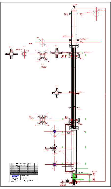
The primary system, Fig. 2-2, consists of a RPV housing the electrically heated fuel rods, the riser and DC paths, the PRZ, the SG helical coil. An outer circulation pump is foreseen with delivery paths to the single SGs. The primary system takes into account the scaling factor for the vertical elevation of the RPV and of RPV connections to the piping is preserved. It is a cylindrical pressure vessel consisting of three main parts coupled by flanges. The lower part contains the fuel
bundle and related box/shield, the lower DC, the fuel bundle support and closure system that allows the rods to exit the RPV bottom.
Figure 2-2. SPES3 RPV layout
The intermediate part contains the riser, with RCCA simulators, and the upper DC with the three SGs. The four helical pipe rows are wrapped around the cylindrical riser. A cylindrical barrel separates the inner row from the intermediate one and another barrel separates the intermediate row from the two outer rows. The upper part contains the PRZ. The core bypass is an outer pipe. The RPV is provided of nozzles for the FL and SL penetration to SGs, for the DVI line connections, for
the pump suction and delivery, for the EBT upper line connections, for the ADS and the core bypass.
The power channel vertical elevation is preserved as in the Westinghouse 17x17 Standard fuel bundle. The bundle geometry (rod pitch and diameter) is preserved. The rod number is scaled by 1:100 (235 heated rods plus one dummy central rod). The active length of the fuel is 4.191 m. The prototypical length below and above the active core is 0.254 m and 0.406 m, respectively for a global length of 4.851 m. In the reactor, this is the fuel length included between the lower and upper core plates. The SPES3 fuel bundle extends downwards for about 0.5 m in order to exit the RPV bottom and connect the electrical poles. A constant axial power profile is provided. The radial profile is uniform with the exception of two hot rods with a peaking factor of 1.2. The outer wall of the fuel bundle box acts as a barrel that separates down comer and riser. The maximum electrical power of 6.5 MW is available for the SPES3 facility power channel. The rod heating mode is indirect, i.e. an electrical resistance is located inside the cylindrical cladding and electrically insulated from the outer shell by a mineral oxide. Both the electrical connections of the positive and negative poles exit from the rod bottom. The rods are maintained in their relative positions by 14 spacer grids located at different elevations along the bundle. The grids are not prototypical and the pressure losses across the core will be adjusted by proper orificing at the core outlet. The rod spacer grids are not prototypical, but the core pressure drops is properly scaled by orificing at the bundle outlet.
The fuel bundle is contained in a double layer box, open at the bottom and top, acting as DC barrel and creating the descending and rising flow paths. The rod spacer grids are welded at the inner layer of the box. The fuel bundle box/barrel structure is chosen by preserving as much as possible the 1:100 scale on the thermal mass. The global heat transfer coefficient is instead 10 times smaller in SPES3 than in IRIS. This compensates for the side surfaces in SPES3 about 10 times larger than in IRIS. In order to simulate the IRIS plant core shield thermal inertia and heat transfer, a double layer box with honeycomb wave fillers inside has been adopted. The thermal and mechanical parameters of the box have been verified showing that the thermal mass ratio and the overall thermal conductance ratio between IRIS and SPES3 satisfy the scaling criteria and that the mechanical structure satisfy the maximum stresses allowable constraints. The fuel bundle box is supported by a perforated cylindrical pipe suitable to drive the DC flow rate toward the fuel bundle. A support and sealing system closes the RPV bottom preventing leakages through the rod penetrations. The sealing system consists of a series of graphite gaskets placed among stainless steel stuffing disks. A closure flange packs the layers and is joined to the RPV by bolts.
rows narrow sections. The riser, SG central columns and annular space are simulated in a unique riser volume. The CRDMs and RCCAs are simulated by scaling volume and mass. The SPES3 riser is a cylindrical volume that simulates all together in a single component the IRIS reactor cylindrical riser, SG annular space and the Central columns. The lower riser contains the RCCAs simulators, while the upper riser contains the CRDMs simulators. The RCCAs and CRDMs are simulated in the SPES3 only from the point of view of occupied volume and pressure drops. They are included in the riser and are simulated simply by pipes and grids. In the IRIS plant, the RCCAs are located in the lower riser and the CRDMs in the upper riser, in SPES-3, a cluster of six 1 inch Sch. 160 pipes goes from the core outlet to the PRZ bottom and 5 grids are located along the cluster: the 3 lower grids simulate the IRIS grids, the 2 upper ones are spacer grids.
The SPES3 inner SG tube row simulates two of eight IRIS plant SGs. It is located in an annulus representing 2/8 of the upper DC. The intermediate SG tube row simulates two of eight IRIS plant SGs. Like the inner row, it is located in an annulus representing 2/8 of the upper DC. The two outer SG tube rows simulate four of eight IRIS plant SGs. They are located in the same annulus representing 4/8 of the upper DC. Each tube row consists of 14 AISI 316 tubes, 17.46 mm outer diameter, 1.688 mm thickness, coiled with an inclination of about 15° for a total length of 32 m and a difference of elevation of 8.2 m. The cross sectional dimensions of the SG annuli are chosen in order to give a performance as uniform as possible among the SGs and as close as possible to the performance of the IRIS plant SG. The two outer rows are coiled with equal inclination to allow enough room for instrument penetration, given that the heat transfer coefficient is not affected by the relative inclination. The SG rows are maintained in both their axial and radial position by four vertical perforated plates welded along the outer wall of each barrel and dividing any annular DC in four quadrants. Such plates, preventing the water flow to follow the tube coil path, force the water circulation in cross flow and guarantee the adequacy of the heat transfer. The holes diameter and shape on the plates allow the installation and thermal expansion of tubes.
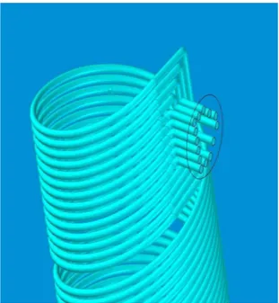
Four helical coil tube rows simulate the eight IRIS SGs (Fig. 2-3). Each row simulates two SGs. The two outer rows are operated as a single SG simulating 4 out of 8 SGs. A direct scaling of SG number of tubes would lead to have in SPES3 facility four rows with 14 inconel 690TT tubes each, outer diameter 17.46 mm, thickness 2.11 mm, average length 32 m, difference of elevation between FL and SL collector center lines 8.2 m. Evaluations on possible thickness reduction and use of cheaper material (AISI 316L) for the facility have led to choose less thick tubes (1.688 mm, same outer prototypical diameter 17.46 mm), 32 m average length, 8.2 m FL and SL collector difference of elevation. The SG zone volume, primary side, cannot be 1:100 scaled as 1:100 scaling of the narrow areas at SG tubes is chosen to preserve pressure drops. This choice and the 1:10 RPV
diameter scale result in a SG volume over-scales as follows: 1:72.5 for SG-A, 1:65.7 for SG-B, 1:56.5 for SG-C. This occurs due to the empty spaces present among the coils of the tube rows that in IRIS are not present being the SG full of tubes.
Figure 2-3. Helical coil sketch
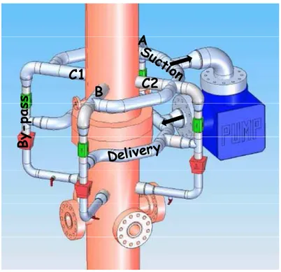
The IRIS plant inverted hat PRZ is simulated in the facility and the inverted hat shape is reproduced by maintaining the plant elevation and PRZ height. The cylindrical shape of the PRZ in SPES-3, to maintain the lower RPV section, does not allow to scale 1:100 the IRIS hemispherical PRZ volume, that results 1:56 scaled. Vertical cylindrical electrical heaters are inserted from the top with the nominal power of 27 kW suitable to compensate heat losses during the steady state and maintain the specified pressure. The connection to the riser is performed by one surge hole whose area is scaled to be 30% larger than the global plant ADS nozzles area in order to avoid critical flow and discharge flow limitation in case of ADS intervention. An electrical vertical heater allows controlling the pressure during the steady state. The PRZ surge hole area is scaled. The IRIS plant pumps, Fig 2-4, are simulated in SPES3 by a single outer pump. The rated flow and head, directly scaled by IRIS are 0.074 m3/s and 19.9 m, respectively. SPES3 will be run at 65% of the nominal flow rate, due to the maximum available power. Consequently the SPES3 pump rated flow rate and head are 0.0481 m3/s and 8.41 m, respectively. In order to be able to regulate or exclude one or more SGs from the operation, the pump delivery is separated toward the three SGs. Four 6 inch Sch. 160 nozzles are related to the pump suction and four equal nozzles are related to the pump delivery. Pump suction and delivery are connected to common circular collectors. Between the delivery collector and the RPV nozzles, four separate lines are provided to distribute and measure the flow to the SGs. Four pump bypasses are provided and located just at the outlet of each nozzle. Each bypass
line contains a check valve which is closed when the pump is in operation and open when it is stopped. Two plates with adequate fissures, welded at different elevations under the pump-RPV connections, allow a symmetric distribution of water injected from the pump at the SGs inlet.
A B C1 C2 By -p as s
Figure 2-4. Pump overview
There are two EBTs. It is a cylindrical vessel with spherical bottoms. Piping connects the EBTs to DVI and RPV (Fig. 2-5).
EBT to RV Balance line EBT-B RV EBT-A EBT-A EBT to DVI EBT-B DVI-A DVI-B RV
2-3-2.
Secondary circuit
The secondary circuit system consists of SG secondary side, EHRS, RWST, it has three loops, each connected to one SG, that allow removing heat generated in the RPV and dissipate it in the SIET condensation and discharge loop.
Two loops are identical and they are connected to the 2/8 SGs, while one loop is larger, being connected to the 4/8 SG. Each loop simulates the IRIS plant pipes up to the main SL and FL isolation valves, while after such valves; the loops need no longer to be prototypical. Feed Lines and Steam Lines are simulated respecting the elevation differences and pressure drops as in IRIS plant.
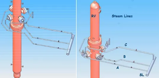
The FL and SL connections to the RPV, Fig. 2-6, consist of 8” Sch.160 nozzles (four for the FL and four for the SL) to allow the SG tubes to exit the RPV. The piping size is chosen to maintain the same pressure drops as in the IRIS plant. In particular: known the pipe routing and size in IRIS and defined the routing in SPES3, the pressure drops are preserved by scaling the mass flow. Commercial pipe sizes available just above the calculated ones are selected. Connections of the EHRS circuit hot leg and Cold leg are present on the SL and FL respectively.
Figure 2-6. Feed Lines and Steam Lines connection to the RPV
The preliminary IRIS plant EHRS design consists of two twin modules of 120 vertical pipes connected to two horizontal cylindrical collectors. IRIS has four EHRS, the SPES3 facility has three, simulating four, each connected to a secondary loop. The EHRS connected to the third loop simulates two EHRSs pertaining to the double loop. The three EHRS are placed in the same RWST. Direct scaling of 1:100 on tubes number has been applied. Due to the need of utilizing commercial pipes, small discrepancies in volume scaling of EHRS headers are accepted. The hot legs and cold legs connecting the EHRS to FLs and SLs has been dimensioned maintaining the same pressure drops as in IRIS, according to the same criterion as for SLs and FLs.
In the SPES3 facility, the EHRS related to each loop is simulated by components with 3 tubes and 5 tubes, relatively to the 2/8 loops and 4/8 loop (2.4 pipes should be needed for each 2/8 loop and 4.8 pipes for the 4/8 loop). A stripe of insulating material will reduce the heat transfer surface on the 3 pipes EHRS to have the equivalent surface of 2.4 pipes. The upper and lower headers are simulated by vertical cylindrical pipes suitable to maintain the correct elevation and the scaled volume. Due to the larger ratio surface over volume in SPES3 than in IRIS, also the cylindrical part of the headers will be thermally insulated. The pipe pitch is the same as the IRIS plant EHRSs and the three components are placed in the same RWST as close as possible among them, in order to have a sort of bundle effect. This solution allows the exclusion of one or more EHRS from the circuit on the basis of the required tests.
The RWST design is strictly related to the EHRS location. The water volume is scaled and the height is maintained. A round base pool contains the three EHRSs. The water volume is 12 m3. In order to maintain the EHRS always covered for a week, considering a water level diminution of about 0.5 m per day, a nominal level of the pool of 9 m is required, this means a pool base area in SPES3 of 1.33 m2. A circular base pool of 1.303 m diameter is hypothesized with 10 m height. The RWST bottom is located 4.277 m above the SL nozzle centerline. In order to avoid water entrainment during the pool boiling conditions, an horizontal circular plate (Ø=1.252 m), joined by slabs to the inner wall of the pool, is installed over the water level and creates a side fissure of 0.1 m2 area. Water drops entrained in the rising steam impact on the plate that operates as a steam/water separator.
2-3-3.
Containment system
The containment system, fig. 2-1, consists of DW,PCC, QT, PSS, LGMS, RC and DVI room, ADS system, DVI, PSS, PSS-LGMS balance lines, PSS to DVI lines, LGMS to DVI lines.
The containment system is simulated by means of different tanks scaled in volume 1:100, in height 1:1 and located at the same elevation as in the IRIS plant. The tank shape is suitable to reproduce the same volume trend versus height of the IRIS plant containment compartments. Piping connects the RPV. Such pipes do not exist in the IRIS plant and thus they are designed in terms of size and layout to limit their influence on the flow. The metal walls of the tanks are dimensioned to resist to the specified design pressure and temperature and on the basis of existing commercial plates. The DW is a cylindrical tank which volume is 35.36 m3 and height is 15.9 m. It is designed as a cylindrical vessel with elliptical ends. The PCC is a condenser installed at the DW top, consisting of an horizontal bundle of 12 AISI 304 U-tubes, 1 inch sch. 40 size, having average length of 2.8 m. The SPES3 PCC doesn’t simulate the IRIS PCC. Its only requirement is to remove
the specified power of 0.5 MW. It is suitable to remove the decay heat from the containment during accidental transients where malfunction of all EHRS is foreseen. It has been designed to remove up to 0.5 MW power. It is feeded by water (1 bar, 50°C) from auxiliary systems and foresees phase change. It actuates on high containment (DW) pressure signal with an on/off operation. The QT is a cylindrical tank which volume is 0.336 m3 and height 3.2 m (0.370 m diameter). It is designed as a cylindrical vessel with elliptical ends. There are two PSSs, Fig. 2-7. The PSS volume is 5.01 m3 and the height is 7 m. It is designed as a cylindrical vessel with two different sections joined by a conical fitting and elliptical ends.Each PSS consists of two different cylindrical tanks connected by a conical fitting (the lower tank volume is 1.5 m3 and 4 m height; the upper tank volume is 3.51 m3 and 3 m height). There are two LGMSs, fig. 2-7. Each LGMS volume is 1.663 m3 and height is 4.2 m. The LGMS is shaped in three cylindrical sections, each 1.4 m high, joined by conical fittings (lower and upper section volume 0.426 m3, intermediate section volume 0.810 m3).
Figure 2-7. LGMSs and PSSs layout
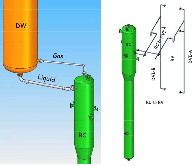
The RC volume is 5 m3. As the lower cavity and DVI room have different sections, this component is simulated with two cylindrical tanks connected by a conical fitting. The global height is 11 m (lower section volume 1.7 m3 and height 7 m, upper section volume 3.30 m3 and height 4 m).
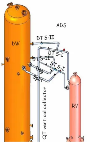
In SPES3 facility, two ADS trains simulate the three of IRIS: a single ADS train simulates two and another train simulates one, Fig. 2-8. Each of the 3 trains of the IRIS reactor consists of two stages: stage I and stage II. Stage I is a 4 inch pipe ending into the QT, while stage II, 6 inch pipe, ends into the DW. The nozzle and pipe size upstream of the ADS isolation valves (on the 4 and 6
inch eq. lines) are chosen to avoid critical flow before the valves themselves. The single train stage I and II pipes are 1 ½ inch sch. 80. The double train stage I and II pipes are 2 ½ inch Sch. 80. The common vertical collector pipe ending into the QT is 3 inch Sch. 40. The proper scaled areas of the ADS stage I valves are set by means of orifices: F=7.019 mm, A = 3.87E-05 m2 for the single train, and F=9.927 mm, A = 7.74E-05 m2 for the double train. The proper scaled areas of the ADS stage II valves are set by means of orifices: F=13.18 mm, A = 1.364e- 4 m2 for the single train, and F=18.64 mm, A = 2.729E-04 m2 for the double train. The ADS line ends into the DW QT with a sparger. A safety valve, as in IRIS plant, is foreseen in SPES-3 to comply with plant simulation and for safety considerations.
Figure 2-8. ADS lines sketch The containment piping are
- The PSS vent lines connect the DW to the PSS ending underwater with a sparger (Fig. 2-9). - The PSS to LGMS Pressure Balance Lines connect the PSS top to the LGMS top.
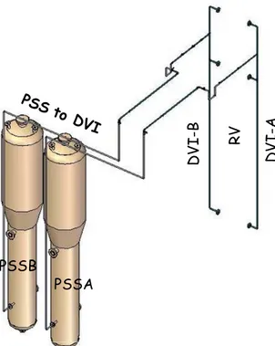
- The PSS to DVI lines connects the water space of the PSS to the DVI line (Fig. 2-10). - The LGMS to DVI lines (Fig. 2-11) connects the LGMS bottom to the DVI.
- The DVI lines.
- The DW to RC lines (Fig. 2-12). - The RC to DVI lines Fig. 2-12).
The DVI line allows the injection of water into the RPV from the EBT, from the cavity, from the PSS and LGMS. Two symmetric DVI lines are foreseen in SPES3, each collecting water from a single train of tanks and from cavity and injecting into the RPV in three points at different elevations. The middle connection is a spare one, (and kept closed by a blind disk), while the main injection occurs into the lower DC. The SPES3 DVI line size is ½ inch Sch. 80.
DW
PS
S
t
o
D
W
PSSB
PSSA
Figure 2-9. PSS to DW sketchPSSB PSSA DV I-A DV I-B RV
Figure 2-10. PSS to DVI sketch
LGMS-B LGMS-A DV I-A DV I-B RV
RC
DW
RC to RV RC RV DV I-A DV I-BFigure 2-12. RC and DW lines and RC to DVI layout
2-3-4.
Break lines
Proper break lines connect the break points to the containment tanks. The piping configuration is suitable to simulate both split and double ended guillotine (DEG) breaks by means of a proper valve configuration. In general, the break position and the piping connections to containment tanks are at the same elevation and the break flow is directly discharged into the containment. Three break locations are foreseen on the primary side: a) lower break at the DVI line; b) upper break at the EBT connection line to the RPV; c) ADS break line. Both split and double ended guillotine (DEG breaks, shown in Fig. 2-13, can be simulated in case of DVI, EBT and ADS single train line breaks. Two break locations are foreseen on the secondary side to simulate the FL and SL split and DEG breaks inside containment.
The lower break line is the DVI break at the RPV injection, before the fork to the two injection points. Small breaks are foreseen and the break size is defined in the test matrix. The lower break discharges into the RC DVI room.
and the break size is defined in the test matrix. The ADS break line is located on the ADS single train simulation pipe, on the 6 inch equivalent line, downstream of the safety valve, and enters the DW at the same elevation. Small breaks are foreseen and the break size is defined in the test matrix. The FL break is located within the containment. The break line connects the FL to the containment tank, in particular to the RC DVI room. The break size is defined in the test matrix. The SL break is located within the containment. The break line connects the SL to the containment tank, in particular to the DW. The break size is defined in the test matrix.
Figure 2-13. Split and Deg layout.
2-3-5.
The auxiliary systems
The auxiliary systems provide water to the test facility at the required temperature, pressure and mass flow. With regard to this matter, some modifications to the already existing systems at SIET were needed to match the IRIS requirements. The Start-up FW is provided by the auxiliary systems at the required pressure, temperature and flowrate.
2-3-6
Thermal insulation
Thermal insulation is foreseen for all SPES3 tanks and piping to reduce heat losses to the environment and to simulate the IRIS plant conditions during steady state and transients. It is constituted by a mineral wool, rockwool or Cerablanket shell, 100 mm thick, covered by an aluminum sheet 1 mm thick.
2-3-7.
Electric heaters on containment tanks
A wire type electric heater will be installed on the outer surface, below the thermal insulation, of all the containment tanks and the EBTs. This will compensate thermal distortions caused by the SPES3 thermal inertia non-properly scaled with respect to IRIS. The required specific power for the DW is 1.5 kW/m2 while it is 1 kW/m2 for all the other.
REFERENCES
• R. Ferri, C. Congiu. Conceptual design of the SPES3-IRIS facility. SIET 01 334 RT 07 Rev.1. September 5, 2008.
• R. Ferri, C. Congiu. SPES3-IRIS facility RELAP5 base case transient analyses for design support. SIET 01 489 RT 09 Rev.0. April 7th, 2009
• F. Bianchi, M. Ricotti, G. Storrick, M. Dzodzo, A. Maioli. SPES-3 Test Specification. Report RSE/2009/70
CHAPTER 3
DESCRIPTION OF SPES3 TRACE MODEL
3-1
SPES III TRACE MODEL OVERVIEW
The SPES3 facility TRACE nodalization is based on the SPES3 geometry briefly described in the previous chapter and in the “Conceptual design of the SPES3-IRIS facility”.
Each part of the SPES3 facility is described together with its corresponding TRACE model. The SPES-3 facility layout of the primary, secondary and containment systems are shown in Fig.3-1. The SPES3 System TRACE nodalization has been developed by maintaining as much as possible the same volume number and vertical discretization as in the SPES3 RELAP5 plant model nodalization described in the paper “IRIS Base Input Deck and Steady State Qualification for
RELAP5 MOD 3.3. WEC STD-ES-04-19 Rev. 2.4” and its updated version, the RELAP model 146.
This choice will make easier the comparison between the results obtained by the two different codes.
3-2
PRIMARY SYSTEM
The SPES3-TRACE primary system nodalization is shown in Fig.3-2. It includes the following main regions:
• Lower downcomer (pipe 101);
• Lower plenum (pipes 102, 103, 104, 105, 106; single junctions 91, 92, 93, 95, 96); • Core (pipe 110);
• Core by-pass (pipes 114, 115; valve 94); • Lower riser, RCCA zone, (pipe 120); • Upper riser, CRDM zone, (pipes 123, 124); • Pressurizer (pipe 130);
• Pump Suction plenum (pipe 150); • Pump (pump 191);
• Pump Suction connecting piping (pipes 700, 710, 720, 730, 170, 172, 176);
• Pump bypass connecting piping and check valves (loop a: pipes 706, 707; check valve 708; pipe 709; loop b: pipes 716, 717; check valve 718; pipe 719; loop c1: pipes 726, 727; check valve 728; pipe 729; loop c2: pipes 736, 737; check valve 738; pipe 739); • Pump delivery connecting piping and valves (pipes 186, 180, 182; loop a:701, 702, 703;
valve 704; pipe 705; loop b: 711, 712, 713; valve 714; pipe 715; loop c1: 721, 722, 723; valve 724; pipe 725; loop c2: 731, 732, 733; valve 734; pipe 735);
• Primary side of SG-A (pipe 211); • Primary side of SG-B (pipe 212); • Primary side of SG-C (pipe 213);
• Riser-SG primary side connection check valves (check valves 161, 162, 163).
The primary system nodalization models the lower DC, the LP, the core, the core bypass, the riser, the PRZ, the pump suction plenum, outlet pump and connecting piping, the SG primary side, the riser to DC check valves. The SPES3 nodalization is based on the design of the Reactor Vessel and its internals. The steel masses are all simulated, outer and inner, and the thermal insulation towards the environment is simulated where present. The environment is represented by an opportune volume where air flows at 0.5 m/s with a temperature of 25 °C. The lower DC includes the SG outlet zone (above the RPV joining flange) and the annular zone around the fuel bundle box. The local pressure drop coefficient at the junction is due to an abrupt area change between the annular zones out of the fuel bundle box and out of the cylindrical riser barrel. The outer wall of the RPV under the RPV flanges, the RPV flanges, the outer wall of the RPV above the flanges and the
metal mass of fillers at the SG outlet are simulated using heat structures thermally coupled to the environment.
The LP includes the lowest part of the annular DC (below the BAF elevation), the annular part outside the perforated cylinder, the cylindrical part inside the perforated cylinder and the inner part of the fuel bundle box up to the BAF. The number of each single junction between the vertical volumes of the lower plenum is justified to simulate the perforated cylinder hole area, that is larger than the volume cross section area. The outer wall of the RV at the LP, corresponding at different diameters, a portion of the cylindrical RV outer wall, the RV metal wall at the LP bottom in the filler zone are simulated by using heat structures thermally coupled to the environment. The core hydraulic path includes the volume inside the fuel bundle box free from the heater rods. The core volume ends at the RV connection flanges. The normal heater rods are simulated by concentric layers of copper, boron nitride, inconel, boron nitride, AISI 316L, from inside to outside. The hot heater rods are simulated by concentric layers of copper, boron nitride, inconel, boron nitride, AISI 316L, from inside to outside. The fuel bundle box is modeled as well. Due to the honeycomb structure of the fuel bundle box, a fictitious material has been used with characteristics averaged on the actual materials of the box and AISI 304. This structure is thermally coupled to the lower DC. The core by-pass is simulated by a pipe parallel to the core. It detaches from the LP and joins to the lower riser, above the RV join flange. It is longer than the core due to mechanical constrains for connections. A valve on the pipe allows to set an area to adjusts the mass flow. The core by-pass heat structures are thermally coupled to the environment. The riser consists of two parts in IRIS: the lower part, containing the RCCAs, and the upper part containing the CRDMs. In SPES3 the RCCAs and CRDMs are simulated simply with pipes and perforated plates and no geometrical difference in cross section areas exists between lower and upper riser. Five perforated plates keep the RCCA and CRDM simulators in place and provide pressure drops. The PRZ consists of two cylindrical parts: the lowest connected to the upper riser by the surge hole and the highest containing the electrical heaters. The detail of the nodalization of the outer pump and the connecting piping, that allows to suck and deliver water to the RV, is shown in Fig.3-3; the pump by-pass and the four branches are shown too. A B C1 C2 By -p as s
The pump characteristics utilized in the nodalization are those of a canned motor pump with large flow and low head.
The three steam generator primary sides are modeled and each annulus contains the SG helical tubes. It includes the zone from the pump connection, above the SG tubes, down to the SG outlet, under the tubes. The nodalization assumes the SG annuli to finish at the same level of the Feedwater nozzle on the vessel. SG-A and SG-B have a single connection from the pump, while SG-C has two. Two water distribution plates are installed at two different levels and with different horizontal orientation of fissures between the pump connection and the SG tubes, in A and SG-B. In SG-C a single plate is installed. The pressure drop coefficients at internal junctions of the pipes are due to the presence of the helical tubes inside the annuli. The coefficients are obtained by specific correlations of in-series tubes with a cross flow stream. The obtained coefficients related to 14 tube rows, plus the dummy tubes, are weighted on the length of each sub-volume the pipe is discretized, and are associated to each internal junction.
The position of check valves that connect the riser to the DC (SG annuli) are shown in Fig. 3-2. In the nodalization three check valves are simulated, one for each SG. Each SG is simulated without any subdivision in quadrant. Each check valve has an equivalent area to eight holes. The local pressure drop coefficients are obtained by abrupt area changes and geometry characteristics. The closure back pressure is set by the weight of the aluminium spheres.
It is important to note that in all check valves used in the nodalization the value of the closure back pressure is always positive.
3-3
SECONDARY SYSTEM AND EMERGENCY HEAT REMOVAL
SISTEMS
The three SPES3 secondary loops are modeled up to the main feed and steam isolation valves and they are thermically coupled to the primary system by the steam generator tubes. Each secondary loop is provided of an EHRS with related hot and cold leg and a heat exchanger located in the Refueling Water Storage Tank. Two RWSTs hosts the EHRS-A/B and the EHRS-C.
The SPES3 secondary system nodalization is shown in figs. 3-4 - 3-6, it includes the following main common regions:
• Feedwater header (pipe 304; break 300);
• Steam header (pipe 750; check valve 752; break 761).
In particular, the secondary system-A includes the main following regions: • Feed line A (TDJ 801; pipes 305, 306; valve 302; pipes 307, 261);
• SG-A tubes (pipe 271);
• Steam line A (pipes 281, 350, 353; valve 355; pipe 354); • EHRS-A hot leg (pipe 501; valve 517; pipe 502);
• EHRS-A heat exchanger (pipes 555, 558, 569);
• EHRS-A cold leg (pipe 507; valve 500; pipe 508; check valve 521; pipe 509); • RWST-A/B (vessel 2, with 25 axial levels, 2 radial rings and 1 azimuthal sector); • Piping connecting the RWST-A/B to the environment (pipe 22; break 535). The secondary system-B includes the main following regions:
• Feed line B (TDJ 802; pipes 315, 316; valve 312; pipe 317; valve 318; pipes 319, 262); • SG-B tubes (pipe 272);
• Steam line B (pipes 282, 366; valve 368; pipes 360, 363; valve 365; pipe 364); • EHRS-B hot leg (pipe 503; valve 518; pipe 504);
• EHRS-B heat exchanger (pipes 574, 597, 579);
• EHRS-B cold leg (pipe 511; valve 522; pipe 512; check valve 523; pipe 513). The secondary system-C includes the main following regions:
• Feed line C (TDJ 803; pipes 325, 326; valve 322; pipe 327; line C1: pipes 337, 263; line c2: pipes 347, 264);
• SG-C1 tubes (pipe 273); • SG-C2 tubes (pipe 274);
• Steam line C (line c1: pipes 283, 380; line c2: pipes 284, 390; pipes 370, 373; valve 375; pipe 374);
• EHRS-C hot leg (pipe 505; valve 519; pipe 506); • EHRS-C heat exchanger (pipes 595, 598, 596);
• EHRS-C cold leg (pipes 514; valve 524; pipe 515; check valve 549; pipe 516); • RWST-C (vessel 3, with 25 axial levels, 2 radial rings and 1 azimuthal sector); • Piping connecting the RWST-C to the environment (pipe 23; break 835).
The secondary system-A consists of the FL-A, the SG-A tubes and the SL-A. The SG-A consists of a single tube row. The nodalization of feedwater header and FL-A is shown in Fig. 3-4.
The EHRS-A consists of the hot leg-A, the heat exchanger-A and the cold leg-A. The HL-A detaches from the SL-A and enters the HX-A top. The HX-A is immersed in the RWST-A/B. The
CL-A exits from the HX-A bottom and connects to the FL-A. In order to limit the discharge flowrate at the moment of EHRS actuation and make pressure drops in the pipe close to the IRIS ones, a calibrated orifice has been introduced at the actuation valve. The outer wall of the HL-A pipe is thermally coupled to the environment, instead the heat structures representing the portion of HL-A inside the RWST-A/B are thermally coupled to the volumes of the special component "vessel" used to simulate the RWST-A/B. The heat structures representing the HX headers and tubes are thermally coupled to the RWST-A/B vessel inner volumes. Also the heat structures representing the portion of CL-A inside the RWST-A/B are thermally coupled to the lowest vessel inner volumes. The heat structures representing the outer wall of the portion of the CL-A pipe external to the RWST-A/B are thermally coupled to the environment.
The RWST-A/B contains both the EHRS-A and B heat exchangers. The heat structures representing the outer wall of the "vessel" RWST-A/B are thermally coupled to the environment.
The secondary system-B consists of the FL-B, the SG-B tubes and the SL-B. The SG-B consists of a single tube row. The nodalization of the feedwater header, the Feed Line and the Steam Line are shown in Fig. 3-5. The EHRS-B consists of the hot leg-B, the heat exchanger-B and the cold leg-B. The HL-B detaches from the SL-B and enters the HX-B top. The HX-B is immersed in the RWST-A/B. The CL-B exits from the HX-B bottom and connects to the FL-B. In order to limit the discharge flowrate at the moment of EHRS actuation and make pressure drops in the pipe close to the IRIS ones, a calibrated orifice has been introduced at the actuation valve. The outer wall of the HL-B pipe is thermally coupled to the environment, instead the heat structures representing the portion of HL-B inside the RWST-A/ B are thermally coupled to volumes of the special component "vessel" used to simulate the RWST-A/B. The heat structures representing the HX headers and tubes are thermally coupled to the RWST-A/B vessel inner volume. Also the heat structures representing the portion of CL-B inside the RWST-A/B are thermally coupled to the lowest vessel inner volumes. The heat structures representing the outer wall of the portion of the CL-B pipe external to the RWST-A/B are thermally coupled to the environment.
The secondary system-C consists of the FL-C, the SG-C tubes and the SL-C. The SG-C consists of two concentric tube rows. The nodalization of the feedwater header, the Feed Line, the Steam Line and the SG tube rows are shown in Fig. 3-6. The EHRS-C consists of the hot leg-C, the heat exchanger-C and the cold leg-C. The HL-C detaches from the SL-C and enters the HX-C top. The HX-C is immersed in the RWST-C. The CL-C exits from the HX-C bottom and connects to the FL-C. In order to limit the discharge flowrate at the moment of EHRS actuation and make pressure drops in the pipe close to the IRIS ones, a calibrated orifice has been introduced at the actuation valve. The pressure drop coefficients at junctions in the pipes and valves keep into account the actual geometry of the lines (bends, concentric reduction/enlargements, etc.).
The outer wall of the HL-C pipe is thermally coupled to the environment, instead the heat structures representing the portion of HL-C inside the RWST-C are thermally coupled to volumes of the special component "vessel" used to simulate the RWST-C. The RWST-C is modeled exactly as RWST-A/B.
Figure 3-6.Secondary system side SG-C nodalization.
3-4
CONTAINMENT SYSTEM AND EMERGENCY SYSTEMS
The containment system compartments and piping are modeled in all their parts, as shown in fig. 3-7. The tanks consist of EBT, LGMS, QT, DW, RC and PSS.
connections, DW to PSS vent lines, PSS to LGMS balance lines, LGMS to DVI discharge lines, RC to DVI lines, PSS to DVI lines, PCC.
The break lines consist of DVI-B break line (lower break), EBT-B to RV line break (upper break), ADS Single Train Stage-I break, FL-B break, SL-B break.
The SPES3 break lines do not exist in IRIS but they are needed in the facility to lead the break flow into the containment tanks. All the break lines are suitable to simulate both the split and double ended guillotine break.
3-4-1. Tanks
The Emergency Boration Tanks are modeled as follows: • EBT-A (pipe 610);
• EBT-B (pipe 630);
Appropriate heat structures represent the cylindrical body and the hemispherical ends of the EBTs. They are thermally coupled to the environment.
The Long Term Gravity Make-up Tanks and the Quench Tank are modeled as follows: • LGMS-A (pipe 406);
• LGMS-B (pipe 408); • QT (pipe 139).
Appropriate heat structures represent the cylindrical body and the hemi elliptical ends of the LGMS and QT. They are thermally coupled to the environment. A special model of drywell condensation has been adopted to take into account the wall condensation phenomena.
The Dry-Well tank is modeled with a three-dimensional "vessel" approach as well as the Pressure Suppression Systems and the Reactor Cavity:
• Dry-Well (vessel 400 (drywell type), with 19 axial levels, 2 radial rings and 4 azimuthal sector);
• PSS-A (vessel 410 (drywell type), with 7 axial levels, 2 radial rings and 2 azimuthal sector);
• PSS-B (vessel 412 (drywell type), with 7 axial levels, 2 radial rings and 2 azimuthal sector);
The DW is shown in fig.3-7 together with its nodalization volumes. The metal wall of the cylindrical and hemi elliptical portions of the DW are all simulated and are thermally coupled to the environment. A special model of drywell condensation has been adopted to take into account the wall condensation phenomena.
The PSS are simulated with the same “vessel” approach as the DW. The PSS-A and PSS-B are shown in fig.3-7, with their nodalization volumes. The metal wall of the cylindrical, conicaland hemi elliptical portions of the PSS are all simulated and are thermally coupled to the environment. As in the DW model, the same model of drywell condensation has been adopted to take into account the wall condensation phenomena.
The RC is simulated with the same “vessel” approach as the DW and the PSS. The RC is shown in fig.3-7. The metal wall of the cylindrical, conical and hemi elliptical portions of the RC are all simulated and are thermally coupled to the environment.
As in the DW model, the same model of drywell condensation has been adopted to take into account the wall condensation phenomena.
3-4-2. Piping
The SPES3 piping includes pipes simulating existing real IRIS plant ones and others needed to connect the containment tanks and to simulate the breaks.
The DVI line are modeled as follows:
• DVI-A vertical part and connections to RV (pipes 603, 600, 616, 615, 614; valves 601, 618);
• DVI-A horizontal part (pipes 642, 640; check valve 641);
• DVI-B vertical part and connections to RV (pipes 623, 620, 636, 635, 634; valves 621, 638);
• DVI-B horizontal part (pipes 662, 660, 663; check valve 661; valve 664).
Two symmetric DVI lines are connected to the RV. The DVI consist of an horizontal part, which all injection points are connected to, and a vertical one joined to the RV. The DVI-A and DVI-B nodalizations are shown in fig.3-7. The pressure drop coefficients at junctions in the pipes and valves keep into account the actual geometry of the lines (bends, concentric reduction/enlargements, etc.).
The EBT loops include the following lines:
• RV to EBT-A balance line (pipes 611, 612, 613);
• EBT-A to DVI-A discharge line (pipes 609, 608; valve 607; pipe 606; check valve 605; pipe 604);
• RV to EBT-B balance line (pipes 631, 632; valve 619; pipes 639, 633);
• EBT-B to DVI-B discharge line (pipes 629, 628; valve 627; pipe 626; check valve 625; pipe 624).
Each EBT is connected to the primary side of the RV by two lines, a balance line at the top and a discharge line at the bottom that inject directly into the DVI. The pressure drop coefficients at junctions in the pipes and valves keep into account the actual geometry of the lines (bends, concentric reduction/enlargements, etc.). In order to limit the discharge flow rate at the EBT actuation and make pressure drops in the discharge line close to the IRIS ones, a calibrated orifice has been introduced at the actuation valve
The ADS system is modeled as follows:
• ADS-single train stage I, from RV to QT (pipes 167, 147, 148; valve 149; pipe 152; valve 153; pipe 134, QT vertical collector: pipe 131);
• ADS-single train stage II, from RV to Dry-Well (pipe 135, valve 154; pipes 155, 156); • ADS-double train stage I, from RV to QT (pipes 168, 141, 142; valve 143; QT vertical
collector: pipe 131);
• ADS-double train stage II, from RV to Dry-Well (pipe 132; valve 144; pipes 145, 146). The ADS group of pipes is shown in fig.3-7. There are two ADS trains, the single and the double train. The Stage-I of each train ends into the QT, while the Stage-II is directly connected to the DW. The pressure drop coefficients at junctions in the pipes and valves keep into account the actual geometry of the lines (bends, concentric reduction/enlargements, etc.). Calibrated orifices set the correct area of the ADS valves: reduced area on the Stage-I lines, to keep into account of the actual kind of valve in the reactor, and full area are on the Stage-II lines.
The QT to Dry-Well line is modeled as follows: • QT to Dry-Well (pipes 556, 438, 557).
coefficients at junctions in the pipe keep into account the actual geometry of the line (bends, reduction/enlargements, etc.).
The Dry-Well to RC lines are modeled as follows: • Dry-Well to RC liquid line (pipes 550, 414, 551); • Dry-Well to RC gas line (pipes 554, 553, 552).
Two pipes connect the DW to the RC: a line to drain liquid and a line to return gas. The pressure drop coefficients at junctions in the pipes keep into account the actual geometry of the line (bends, concentric reduction/enlargements, etc.).
The Dry-Well to PSS vent lines are modeled as follows:
• Dry-Well to PSS-A (pipes 470, 416, 11, 471, 472; check valve 473); • Dry-Well to PSS-B (pipes 480, 418, 481, 482; check valve 483).
Two vent lines connect the DW to the PSSs. Each lines is joined in two points on the DW and ends into a PSS with a sparger. The upper connection on the DW is open, while the lower one contains a check valves that prevents reverse flow from the PSS.
The DW to PSS vent lines nodalizations are shown in fig.3-7. The pressure drop coefficients at junctions in the pipes keep into account the actual geometry of the line (bends, concentric reduction/enlargements, etc.). The PSS sparger is simulated as a local pressure drop coefficient and a restricted area. The heat structures representing the wall of the DW to PSS vent lines are thermally coupled to the environment.
The PSS to LGMS pressure balance lines are modeled as follows: • PSS-A to LGMS-A (pipes 417, 422, 420);
• PSS-B to LGMS-B (pipes 407, 424, 421).
A balance line connects the LGMS top to its corresponding PSS top. The PSS to LGMS nodalizations are shown in fig.3-7. The pressure drop coefficients at junctions in the pipes keep into account the actual geometry of the line (bends, concentric reduction/enlargements, etc.).
The LGMS to DVI discharge lines are modeled as follows:
• LGMS-A to DVI-A (pipes 429, 430; valve 423; pipe 425; check valve 602; pipe 427); • LGMS-B to DVI-B (pipes 431, 432; valve 433; pipe 435; check valve 499; pipe 437). A discharge line connects each LGMS bottom to its corresponding DVI line. The LGMS to
DVI discharge lines are shown in fig.3-7. The pressure drop coefficients at junctions in the pipes keep into account the actual geometry of the line (bends, concentric reduction/enlargements, etc.). In order to limit the discharge flowrate at the LGMS actuation and make pressure drops in the discharge line close to the IRIS ones, a calibrated orifice has been introduced at the actuation valve.
The Reactor Cavity to DVI lines are modeled as follows:
• RC to DVI-A (pipes 404, 434; valve 460; pipe 461; check valve 140); • RC to DVI-B (pipes 405, 436; valve 452; pipe 462; check valve 151).
A line connect the RC to each DVI line. The RC to DVI lines are shown in fig.3-7. The pressure drop coefficients at junctions in the pipes keep into account the actual geometry of the line (bends, concentric reduction/enlargements, etc.).
The PSS to DVI lines are modeled as follows:
• PSS-A to DVI-A (pipes 393, 426; valve 394; pipe 395; check valve 396); • PSS-B to DVI-B (pipes 409, 428; valve 397; pipe 415; check valve 419).
A line connect each PSS to its corresponding DVI line. The PSS-A to DVI-A and PSS-B to DVI-B lines are shown in fig.3-7. The pressure drop coefficients at junctions in the pipes keep into account the actual geometry of the line (bends, concentric reduction/enlargements, etc.).
The PCC is modeled as follows:
• PCC (break 590; TDJ 591; pipe 592; break 594).
The PCC tube bundle geometry is shown in fig.3-7. The pressure drop coefficients at junctions in the pipe keep into account the actual geometry of the tubes (bends, reduction/enlargements, etc.).
3-4-3. Break lines
All the break lines are modeled as split and double ended guillotine. The DVI break lines (lower break) are modeled as follows:
• DVI-B break split to RC (pipe 665; valve 666; pipes , 667, 668); • DVI-B break DEG to RC (pipe 675; valve 676; pipes 677, 678).
The DVI break line system connects the DVI-B to the RC. The line close to the RV is classified as SPLIT, while the one close to the containment is classified as DEG. The pressure drop
coefficients at junctions in the pipes keep into account the actual geometry of the line (bends, concentric reduction/enlargements, etc.).
The RV to EBT balance line break lines (upper break) are modeled as follows: • EBT-B line break split to DW (pipe 622; valve 643; pipes 644, 645); • EBT-B line break DEG to DW (pipe 652; valve 653; pipes 654, 655).
The EBT-B to RV balance line break system connect the EBT top line to the DW. The line close to the RV is classified as SPLIT, while the one close to the containment is classified as DEG. The EBT-B to RV SPLIT and DEG break lines are shown in fig.3-7.
The ADS single train break lines are modeled as follows:
• ADS ST break split to DW (pipe 157; valve 158; pipes 133, 159); • ADS ST break DEG to DW (pipe 126; valve 127; pipes 128, 129).
The ADS single train break system connects the ADS Stage-I to the DW. The line close to the RV is classified as SPLIT, while the one close to the containment is classified as DEG. The ADS SPLIT and DEG break lines are shown in fig.3-7.
The Feed Line break lines are modeled as follows:
• FL-B break split to RC ((pipe 565; valve 566; pipes 567, 568); • FL-B break DEG to RC (pipe 560; valve 561; pipes 562, 563).
The FL-B break system connects the FL-B to the RC. The line close to the RV is classified as SPLIT, while the one close to the containment is classified as DEG. The FL-B SPLIT and DEG break lines are shown in fig.3-7. The pressure drop coefficients at junctions in the pipes keep into account the actual geometry of the line (bends, concentric reduction/enlargements, etc.).
The Steam Line break lines are modeled as follows:
• SL-B break split to RC (pipe 575; valve 576; pipes 577, 578); • SL-B break DEG to RC (pipe 570; valve 571; pipes 572, 573).
The SL-B break system connects the FL-B to the DW. The line close to the RV is classified as SPLIT, while the one close to the containment is classified as DEG. The SL-B SPLIT and DEG
break lines are shown in Fig.3-7. The pressure drop coefficients at junctions in the pipes keep into account the actual geometry of the line (bends, concentric reduction/enlargements, etc.).
Figure 3-7.Containment system nodalization.
The main SPES3-TRACE containment system characteristics are reported below:
DW volume 32.27 m3 (Di = 1.62 m);
DW thickness 15 mm (corresponding to design pressure of 1.5 MPa);
LGMS volume 1.5 m3 (Di top and bottom = 0.554 m; Di middle = 0.831 m); LGMS height 4 m;
LGMS thickness top and bottom 8 mm, middle 10 mm; LGMS to DVI line calibrated orifice diameter 3.6 mm; LGMS initial level set to have 1 m3 water;
PSS volume 4.59 m3 (Di top = 1.182 m; Di bottom = 0.679 m); PSS thickness top 12 mm, bottom 8 mm;
Main PSS vent pipe diameter 2 ½” Sch. 40 (Di = 62.7 mm); Extension PSS vent pipe diameter 1” Sch. 40 (Di = 26.6 mm);
Extension PSS vent pipe length matches the IRIS length: connection to DW 20.664 m from RV bottom;
PSS vent pipe extension to DW calibrated orifice diameter 17.5 mm;
QT volume 0.336 m3 (Di = 0.37 m); QT thickness 6 mm;
RC volume 4.5 m3 (Di top = 0.961 m; Di bottom = 0.553 m); RC thickness top 10 mm, bottom 8 mm;
RC to DVI line calibrated orifice diameter 1 mm;
DW, LGMS, PSS, QT, RC heat structure initial temperature 84 °C;
ADS ST Stage-I calibrated orifice diameter 5.637 mm; ADS DT Stage-I calibrated orifice diameter 7.973 mm;
EHRS Cold Leg-A and B sized to ½” Sch. 80; EHRS Cold Leg-C sized to ¾” Sch. 80;
EHRS-A and B CL calibrated orifice diameter 5.9 mm; EHRS-C CL calibrated orifice diameter 8.3 mm;
EHRS-A and B: 0.6 tubes out of 3 thermally insulated with Teflon to simulate 240 IRIS-EHRS tubes; 4% total extra surface covered to compensate for AISI-304 instead of Inconel-600;
EHRS-C: 0.2 tubes out of 5 thermally insulated with Teflon to simulate 480 IRIS-EHRS tubes; 4% total extra surface covered to compensate for AISI-304 instead of Inconel-600;
EHRS Hot Leg-A and B sized to 1 ¼” Sch. 80; EHRS Hot Leg-C sized to 2” Sch. 80;
EHRS HL-C inlet orifice (D = 24 mm ) for pressure drop adjustment;
EHRS tubes without heat transfer multiplication coefficient;
RWST-A/B and C “vessel”: Hot column area-inner ring flow area 0.119167 m2-; Cold column area-outer ring area 1.601169 m2- (according to PERSEO experimental results, as regard the EHRS heat transfer parameter);
RWST top pipe connection to atmosphere control volume;
Inlet orifice at SG (D = 11.7 mm) for SG parallel tube row oscillation reduction.
Table 3-1 summarizes the “figures” typifying the TRACE V5p1 code input model of SPES3.
Table 3-1. Figures typifying the SPES3 model
Breaks 9 Pipes 245 Pumps (5 TDJ) 6 Single Junctions 6 Valves 72 Hydraulyc Components 344 Vessel 6 Trip 177 Arithmetic 263 Controller 3 Logical 127 Manipulation 14 Control Blocks 465 Time Related 58 General 7 Volumetric 333 Edge 4 Heat 30 Signal Var ia b les 638 Control 264 Control Systems 1287 General Tables 7 Heat Structures 353 Thermal
365 User Defined Materials 12 Power Components 4
REFERENCES
R. Ferri, C. Congiu: Conceptual design of the SPES3-IRIS facility. SIET 01 334 RT 07 Rev.1. Piacenza (I), September 5th, 2008
CHAPTER 4
STEADY STATE ANALYSIS and RESULTS
4-1. INTRODUCTION
Preliminary analyses, by TRACE system code, have been carried out to set up the SPES 3 model and to determine the steady state conditions at the power of 10 MW, that is the initial conditions to be applied to the analyses of the experimental tests for studying both the integral effects and the specific effects. This first stage will allow the pre-test analyses and the main transients foreseen by the “test matrix” with particular attention to the Test N° 1 analysis which is the reference transient.
In the future, when the facility will be available, the model for TRACE code should be updated according to the “as-built” facility. Such model would allow to simulate all the transients foreseen by the test matrix and help to define the test plan and procedures.
The test matrix on the SPES3-IRIS facility includes integral and separate effect tests. They are summarised in Tab. 4-1 and Tab. 4-2, respectively.
All input have been developed by SNAP code. The Symbolic Nuclear Analysis Package (SNAP) consists of a suite of integrated applications designed to simplify the process of performing engineering analysis. SNAP is built on the Common Application Framework for Engineering Analysis (CAFEAN) which provides a flexible framework for creating and editing input for engineering analysis codes as well as extensive functionality for submitting, monitoring, and interacting with the analysis codes. The modular plug-in design of the software allows functionality to be tailored to the specific requirements of each analysis code.
SNAP currently includes support the CONTAIN, COBRA, FRAPCON-3, MELCOR, PARCS, RELAP5 and TRACE analysis codes. Each code is supported by a separate plug-in.
RELAP5 was developed for best-estimate transient simulation of light-water reactor coolant systems, and models the reactor coolant system coupled with the core for loss-of-coolant accidents. Its generic modeling approach permits simulating a variety of hydraulic systems.