Received 1 February 2016; revised 19 May 2016 and 15 September 2016; accepted 14 November 2016. Date of publication 16 January 2017; date of current version 27 January 2017.
Digital Object Identifier 10.1109/JTEHM.2016.2635635
A Versatile Ultrasound Simulation System for
Education and Training in High-Fidelity
Emergency Scenarios
SAVERIO FARSONI1, LUCA ASTOLFI2, MARCELLO BONFÈ1, SAVINO SPADARO2, AND CARLO ALBERTO VOLTA2
1Department of Engineering, University of Ferrara, 44122 Ferrara FE, Italy
2Department of Morphology, Surgery and Experimental Medicine, Institution of Anesthesia and Intensive Care, University of Ferrara, 44122 Ferrara FE, Italy CORRESPONDING AUTHOR: S. Farsoni ([email protected])
This work was supported by the Arcispedale Sant’Anna of Cona, Ferrara, Italy.
ABSTRACT Point of care ultrasonography and the related focused assessment with sonography for trauma protocol, if performed by experienced physicians, is a highly sensitive examination, and specific for the detection of free fluids. Different systems and methods have been proposed for training, including simulation as one of the most efficient. This paper presents an ultrasound training system, specifically designed to be used during bedside high fidelity simulation scenarios, that could facilitate the learning process. The development of the proposed system exploited novel rapid prototyping electronic boards as a means to obtain good performances with a low cost. Moreover, the design of the data structure permits the construction of a library that caters for individual needs, with the possibility of adding emergency scenarios, collecting pictures or videos, as well as 3-D volumes. The device has been compared with currently commercial ultrasound simulators and its innovative aspects have been highlighted. Finally, it has been tested during a training session in order to evaluate features, such as realism and user-friendliness.
INDEX TERMS Biomedical image processing, medical simulation, point of care ultrasonography, sensor systems and applications, training, ultrasound.
I. INTRODUCTION
U
LTRASOUND examination is rapidly increasing its usage in acute care specialties because of the evolu-tion of Point-of-Care Ultrasonography (PoCUS) [1]: a novel patient’s bedside approach for diagnostic purposes. In emer-gency medicine, where the needs of rapid assessments are strongly prominent, the ultrasound-assisted examination is the new trend. In this mainframe, several standardized pro-tocol for ultrasound-guided procedures have been proposed, such as the Abdominal and Cardiac Evaluation with Sonog-raphy in Shock (ACES) [2] or the Focus Assessment by Sonography in Trauma (FAST). They consist of a series of ultrasound scans focused on the proper windows in order to detect the presence of free fluid on critical traumatized patient.The aim of FAST examination is to identify hemoperi-toneum, hemothorax, or cardiac tamponade [3]. Hence train-ing physicians to perform FAST examination is of great
interest, allowing them to accomplish the skills necessary to acquire the adequate window as well as the ability to identify the presence of free fluids [4]. In sonography, image acquisition is complex and operator dependent: the quality of a scan may reflect the degree of training and there is a significant learning curve [5], [6]. Good transducer place-ment and orientation plus familiarity with US anatomy are required. It has previously been demonstrated that simulation may provide an efficient way of training [7]. Trainees using a US simulator have the opportunity to determine whether to use bedside ultrasound (indications), how to hold and place the probe properly (image generation) and, finally, how to assess scans (image interpretation) within the context of a high fidelity simulation scenario [8], [24]. Such training may involve great expense and should be based on the creation of image database to cover different clinical conditions. Unlike a few years ago, there are now many ultrasound simulators, with different technologies to calculate the orientation and 2168-2372 2017 IEEE. Translations and content mining are permitted for academic research only.
a complete and efficient simulation system. Unfortunately, several of these features contradict each other, in particu-lar high-fidelity often means an expensive equipment which includes the sensors, the controller boards and the visual-ization systems. The hardware, as well as the software and the tracking algorithm, here proposed is an upgrade of the prototype described in [9] with an improved care about the trade-off between cost and quality.
A. HARDWARE
The probe represents the main component of the simulator. It can be used jointly by any holding manikin, or even a human model. It consists of a printed shell of plastic material, containing the electronic boards. The shape of the probe should be as much as possible similar to a real ultrasound transducer, however its dimensions are physically limited by the size of the internal components, so that a meaningful selection criterion considered in the choice of the boards and the sensors has been their dimensions, as described in the following. Because of the symmetry of an ultrasound transducer, the probe is easily made up of two equal parts, built by a 3D printer.
Regarding the internal electronic components, they have to perform the acquisition, the elaboration and the transmission of the data concerning the information about the probe pose, understood as the combination of its position and orientation relative to the manikin. The adopted solution exploits low-cost Radio Frequency Identification (RFID) sensors and Iner-tial Measurement Units (IMU): such technologies, in the last decade, has undergone a noteworthy diffusion in the context of various medical applications [22], [23]. The position of the probe is tracked using a RFID reader that acquires the code of a set of RFID markers located under the manikin skin, in the points of interest chosen by the user (e.g. those assigned by the FAST protocol). It is worth noting that markers can be placed in any desired anatomic area, so that the simulation scenario is not limited to the sole FAST examination (that typ-ically involves ten landmarks). Therefore, also the number, as well as the position, of the RFID markers can be chosen by the user. The adopted sensor is the Innovation RID-12: a programmable low-cost RFID reader, measuring only 25 mm × 25 mm × 6 mm. Markers are standard 12 byte code,
itself. The code identifies uniquely the anatomical landmark selected. The distance between two RFID markers should be at least equal to the RFID read range, in order to avoid the acquisition of a wrong code. This limitation does not affect the proper functioning of the system. Indeed, the anatomical areas considered in FAST protocol are typically placed at a distance of at least 5 cm.
The tracking of the probe orientation is a more challenging problem to overcome. Several algorithms for the estimation of the orientation of a rigid body in the Earth Reference Sys-tem have been developed and applied in different engineering domains [10], [11], including aerospace and robotics. Com-monly adopted solutions concern the data coming from the on-board IMU sensors (accelerometer, gyroscope, and mag-netometer) properly fused and processed through a nonlinear complementary filter [12], [13]. The study of the orientation tracking algorithm in the context of the ultrasound simulator application is described in detail in [9].
In order to obtain the orientation of the probe relative to the manikin, another IMU, with the same sensor equipment, but connected to the manikin itself, has to be exploited. The difference between the orientations relative to the Earth reference system of the two inertial platform is the desired information.
The InvenSense RMPU9250 is a low-cost, small size IMU, containing the accelerometer, the magnetometer and the gyro-scope within a sole microchip: it represents a suitable solu-tion for the requirements of the simulator. Furthermore, this device features a Digital Motion Processor (DMP) capable of processing the orientation tracking algorithm. In more details, technical specifications for the inertial sensors are reported in Table 1.
The data acquisition from the RFID reader and from the IMU is performed by the Teensy R3.2: a 30 mm×17 mm low-cost microcontroller based on a 32-bit ARM Cortex 72 MHz. This compact board is compatible with the widespread Arduino hardware and software environments [14]. Once the estimation of the probe pose has been performed, the micro-controller send the real-time information to the visualization system, as described in the following, through the serial bus. An overview of the exploited hardware components is reported in Figure 1 and Figure 2.
FIGURE 1. The hardware components of the system, with the power supply and information flow charts. From up to down: the marker, the probe with its inner boards (the RFID reader, the IMU and the microcontroller), and the Windows device hosting the application.
B. EXPERIMENTS ON DMP ACCURACY
The accuracy of the relative orientation probe-manikin depends on the accuracy of the estimation provided by the DMPs integrated into the two IMU boards exploited to track the probe and the manikin. Therefore, the performance of DMP as inertial tracker has been studied by means of the following experiment.
A probe containing the microcontroller and the IMU has been fixed to the end-effector of a robot manipulator PUMA260 so that the IMU reference system is initially aligned to the robot reference system. It can be assumed that the forward robot kinematics provides the real-time reference value for the orientation of the end-effector and the IMU. Then, the robot end-effector has been forced to move from an initial orientation of20 =[0, 0, 0] deg, in terms of nautical angles roll, pitch, yaw, to an orientation of21=[45, 0, 0] deg and then come back to20. In the meanwhile, the orientation estimations of the DMP have been acquired. Figure 4 shows the comparison between the robot reference signal and the DMP estimation, considering the transient of the roll angle estimation. The signals have been synchronized.
The percent root mean square error (RMSE%) and the variance of the error between the DMP estimations and the reference robot signal have been computed as performance indices considering the steady condition after the first robot movement. Results are reported in Table 2. The obtained
FIGURE 2. The RFID markers placed under the manikin skin (a) and the assembled components into the simulator probe (b).
values demonstrates that the DMP performances satisfy the requirement of the application. Indeed, it has been observed that even expert users cannot detect errors in image visualiza-tion for values of RMSE%< 5%.
C. THE VISUALIZATION SYSTEM
The visualization system has been developed as a versatile tool, as it allows users to interact with static images, videos or 3D interpolated volumes, coming either from real ultrasound scans or from computer graphic virtualization, depending on the availability of the database.
The displaying of a static image or a video does not require any particular elaboration. However, the software permits to insert different videos or images within a single view: the selection of the proper dataset depends on the current probe orientation. As a result, the user can visualize, for example, a video for the sagittal plane and another one for the longitudi-nal plane, concerning the same anatomical landmark.
3D volumes are processed by the visualization system using two interpolative steps. Firstly, the volume is created by fetching from the database the related set of 2D slices, all of them having the same cutting plane. Afterwards, the resulting volume is real-time sliced, along the plane properly tilted on the basis of the information about the probe orientation, so that the current image can be displayed. The choice of gen-erating volumes from slices instead of managing 3D models
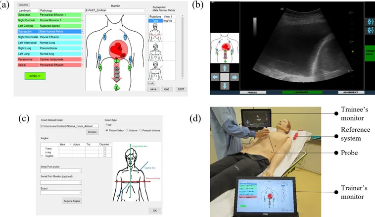
FIGURE 3. The trainer’s GUI (a), the trainee’s GUI with the visualization of an interpolated image (b), the user-extensible database editor (c) and the system set-up (d) which includes the instructor’s and the trainee’s devices, the probe and the manikin reference system.
directly, is due to the user difficulties to obtain that kind of dataset.
Furthermore, in order to overcome this problem, a novel feature has been implemented on the simulator: the so-called pseudo-volume. It is created by acquiring a real video of a pathological case: the operator has to locate the ultrasound transducer on the desired anatomical landmark and rotate it along its axis of approximately 360 deg. Once the video has been acquired and inserted into the simulator database, the visualization system can select the proper frame run-time, basing on the probe orientation. The main advantages of pseudo-volumes are the easiness and the quickness of acquisition. Indeed, medical operators can get the basic video during their normal activity, without any risk for patient health. Pseudo-volumes offer a very realistic simulation when the probe is rotated along its axis, but this degree of freedom is the only one that can be processed by the visualization system. When the probe is tilted along the other axes, the orientation changing effects are not simulated correctly.
Further development are required to include four-dimensional dataset, as volumes or pseudo-volumes does not fit for dynamic dataset visualization, in which the time is a prominent component (e.g. cardiac ultrasound).
The graphic tool exploited by the simulator is the Visual-ization Toolkit (VTK): an open source set of graphic libraries commonly used for scientific data processing [25]. It provides
powerful and optimized functions to manage huge dataset and to render appropriate views on the screen.
D. INSTRUCTOR AND STUDENT SIDE SOFTWARE INTERFACES
According to the increasing demand of standardized profi-ciency assessment procedures [15], the software provides a typical instructor-student behavior allowing a possible usage as a skill-trainer device [16]. Furthermore, the proposed sim-ulator features two separate Graphical User Interfaces (GUIs) that make the device compatible with a complete high-fidelity simulation session [24].
Two different applications have been developed in Microsoft .NET Rframework so that they can run on any Microsoft Windows device. One application is executed on the instructor device, and allows the trainer to select the desired scenario from the case database. The screen is divided into three sections: the central one shows a picture of the selected manikin with its numbered landmarks. A table item-izing the landmarks and the associated pathology is located on the left, whereas the table on the right summarizes the information about the available dataset for a selected cou-ple landmark-pathology. Once the instructor has choose the desired scenario, it can be transmitted to the student appli-cation through a network socket. Figure 3 (a) shows the instructor’s GUI.
FIGURE 4. The DMP estimations during the transient of the roll angle, compared to the robot reference signal.
TABLE 2. Performance indices of DMP estimations.
The student application hosts the database and the visual-ization system, as its main purpose is the simulation of the ultrasound monitor. It is connected to the probe microcon-troller via serial bus and it receives the current information about the probe pose, so that the visualization system can gen-erate the proper view. The trainee can interact with the system freezing the current view and performing some measurements as in a real ultrasound monitor.
The application has a multithread architecture, as multiple operations have to be perform at the same time. The core threads take care of the communication with the instructor application, as well as the transmission of the current dataset to the visualization thread, once the on-line acquisition of the probe orientation has been performed. On the other hand, the visualization thread implements the VTK pipeline and provides the rendered view to the monitor. Figure 3 (b) depicts the trainee’s GUI, while Figure 3 (d) shows the overall system set-up.
E. PERFORMING THE SIMULATION
As mentioned above, the choice of developing two separated GUIs allows an effective usage of the system in high-fidelity simulation scenarios. Indeed, a typical emergency scenario is represented by means of two separated environments: the director room, where the instructor handles the manikin parameters and the simulation room, where the trainee exam-ines the manikin representing the patient. It is often required that the trainee have no contact with the trainer during the session, but the instructor can observe the scene and modify the manikin parameters, on the basis of the trainee’s actions.
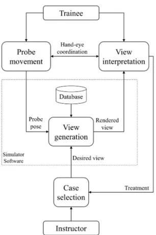
FIGURE 5. The flowchart of a simulation session, where the instructor changes the simulation parameter in real-time, on the basis of the trainee’s actions.
Therefore, the proposed simulator can be applied to that kind of scenarios as follows:
1) The instructor selects the desired case, which is loaded by the visualization system from the database, so that the desired view can be generated on the trainee’s monitor, on the basis of the probe pose information; 2) The trainee uses the simulator probe to perform the
ultrasound examination on the manikin. It mainly regards the hand-eye coordination in the simultaneous actions of moving the probe and interpreting the visu-alized view.
3) The trainee performs a treatment on the patient, based on the diagnosis;
4) The instructor selects a different case in response to the treatment, so that the trainee can analyze the real-time effect of its actions.
Figure 5 shows the flowchart of typical high-fidelity sim-ulation session.
F. THE USER-EXTENSIBLE DATABASE
The simulator implements a user-friendly editor, whereby the operator can manage the database by adding, removing or modifying cases. Therefore, the user is stimulate in acquiring images, videos, volume slices, and pseudo-volumes from real examinations, in order to customize the database according to
its own needs. The collected material can be easily shared among users. The operator who performs the acquisition of a data set from the patient has to provide a sufficiently accurate description of probe position and orientation during the acquisition. A video can be acquired when the probe is motionless and directly inserted into the database, while a volume can be elaborated from the frame sequence of a video acquired by means of a probe translation (of about 2 cm). Similarly, a pseudo-volume is generated on the basis of the frame sequence of a video in which the probe rotates around its axis. Figure 3 (c) shows the editor of the user-extensible database.
III. COMPARISON OF ULTRASOUND SIMULATORS
An overview on similar computer-based ultrasound simu-lators can be found in [17], where the authors describe the main features of their design. In this work, an updated comparison is shown, but the focus is placed on the charac-teristics of each device from the user point of view. The sim-ulators included into the comparison are: SonoSim , CAER Vimedix R, Schallware R[18], HearthWorks R[19], Simu-Lab SonoMan R, as well as the proposed simulator.
The ultrasound visualization system is the first key-point considered: CAE Vimedix and HeartWorks exploit generative model-based views, coming from the elaboration of a virtual model of the patient. The realism depends largely on the fidelity of the model and the building of the model itself is a time consuming procedure, which restrains the diffusion of multiple cases. Schallware, SonoSim and the proposed
simulator use interpolative methods to process real datasets characterized by more than two dimensions. However, it is worth observing that the proposed simulator can visualize also generative model-based views, pre-elaborated in form of image sequences. This feature allows the usage of the simula-tor for basic skill training, while in a simulation session users tend to prefer interpolated real views, because of their higher realism. In this context, another peculiarity of the proposed system is the opportunity to visualize static images, videos, volumes, or pseudo-volumes, depending on the available data sets.
The second feature analyzed is the probe tracking sys-tem. Almost every simulator implements the pose tracking, including position and orientation of the probe, but this result is achieved exploiting different methods. The trade-off is between costs and tracking accuracy: Schallware, CAE Vimedix, and HeartWorks simulators use an expensive elec-tromagnetic system to record the probe pose relative to the manikin. A device rigidly connected to the manikin generates an electromagnetic field. Then, the probe perturbs the field as a function of its position and orientation, so that the probe pose relative to the manikin can be calculated in every point inside the field. The effect of electromagnetic disturbances could be a drawback.
The SonoSim and the proposed simulators have a cheaper RFID - IMU system that provides a discretized solution for the position as well as a less accurate estimation of the orientation, though achieving satisfactory performances. The Simulab SonoMan can track only the probe position.
Some simulators (i.e. the SonoSim and the Simulab Sonoman) do not include a reference system for the manikin, which is instead exploited by the proposed system, CAE Vimedix, Schallware and HeatWorks, to allow the real-time tracking of the relative orientation probe-manikin. Simulators without that feature require the execution of an alignment procedure every time the manikin is accidentally moved.
A further index of comparison is the ultrasound techniques which can be performed. As mentioned above, the proposed device can simulate TTE and abdominal examinations. The same applications are related to Schallware, SonoSim and Simulab, while Heartworks and CAE Vimedix are designed for TTE and TEE.
Finally, two noteworthy features that characterize the pro-posed simulator with respect to the others are highlighted. Firstly, the two separated GUIs make the system compat-ible with a high-fidelity simulation session. Secondly, the extensible database offer the user the opportunity to freely manage the database, while most of commercial devices pro-vide a limited number of case modules, not completely free available.
Table 3 shows the comparison among the considered simu-lators. The last column reports an approximate cost analysis, which considers only the device cost, and not the additional modules. For the proposed simulator the commercial cost is not yet specified, but since the overall hardware cost is about 300 $, it can be expected that a commercial version would cost ten times less than the cheapest mentioned alternative.
IV. RESULTS
The simulator has been tested and evaluated during a training session in the context of the 10thnational Workshop
on Trauma: Update and Organization, held in Bologna (Italy) in February 2015. A group of physicians from the Maggiore Hospital of Bologna, with a prominent ultrasound experience, held a course on the usage of the ultrasound examination in trauma, particularly focused on the FAST protocol. The participants were 15 anesthesiologist, coming from different national hospitals, with a very low ultrasound experience. During the morning, they were given a theoretical lesson on FAST background and methods, whereas in the afternoon, they were subdivided into three workstations, each of them consisting of a simulator and a tutor, who selected the desired case and assists the residents training. Every data set was previously acquired by the tutor itself, in the form of real ultrasound scans (images, videos, and 3D pseudo-volumes).
The manikins used jointly by the simulator were the SimMan RLaerdal, a well tested [20] high-fidelity patient simulator.
The trainees had to apply the FAST protocol by positioning and orientating the probe correctly, and they had the proper monitor response.
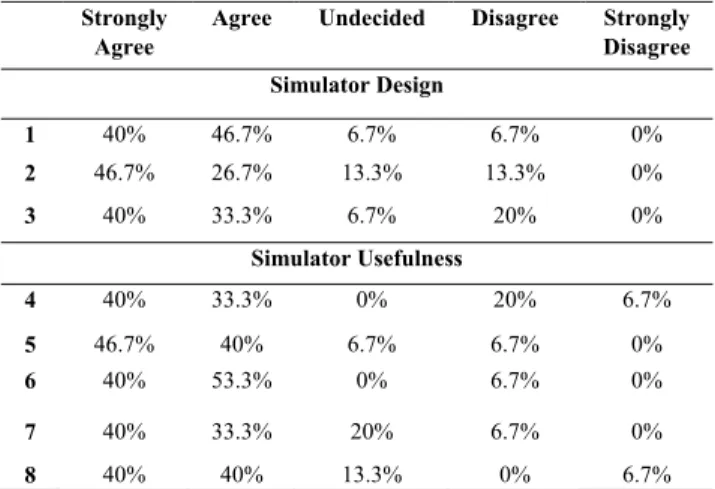
At the end of the training session, the participants were asked to evaluate the simulator. The proposed 5-point Likert-scale questionnaire about the impression and usefulness of the simulator follows the guidelines described in [21] but
TABLE 4.Questionnaire results.
adapted for the ultrasound simulation. The questionnaire is reported in the following, and Table 4 shows the results.
Questionnaire:
1) What is your opinion about the appearance of the sim-ulator?
2) What is your opinion about the realism of the simula-tor?
3) What is your opinion about the user-friendliness of the simulator?
4) What is your opinion about the simulator’s usefulness in improving hand-eye coordination?
5) The simulator can become a useful instrument to train novice physicians in ultrasound techniques.
6) The simulator is a useful instrument to teach basic ultrasound procedures.
7) The simulator can become a useful instrument to mea-sure ultrasound procedure performance.
8) The simulator was a useful instrument to improve ultra-sound skills.
The first three questions concern the participants’ impres-sion about the appearance, the fidelity, and the user-friendliness of the simulator: most responses (more than 70%) are good/excellent (4/5 Likert-scale points), whereas less than the 20% of the participants gave a medium-bad score (2 points). This result validates the simulator as a user-friendly device and motivate further improvements, particu-larly in the visualization of dynamic 4D datasets, in which the time is a prominent dimension. Volumes or pseudo-volumes are not a suitable solution to represent them, as their acquisi-tion procedure entails the loss of time evoluacquisi-tion.
The other questions are about the usefulness of the simula-tor. Also the results in this section are quite positive: indeed, about the 80% of the participants states that the simulator is a useful instrument in medical education (teaching as well as learning) and training. Moreover, it could be exploited as an indicator of ultrasound procedure performances.
Further studies are needed to verify whether the system has positive long-term learning effect.
the design and the usage of the simulator. As a result, most of the participants assert that the proposed simulator is a useful tool to improve ultrasound skills.
Potential issues that could be faced during the commercial-ization involve the creation of a large and complete database to attach to the simulator. Indeed, certain pathologies are difficult to find because of their rarity and other pathologies can be difficult to acquire because of the urgent treatment required by the patient. Nevertheless, users are always able to customize the system with their own database of images, acquired during clinical practices. Moreover, the feedback of users belonging to different medical disciplines can be useful to properly extend the usage of the simulator in such disciplines.
Further developments could concern the visualization of time-varying ultrasound volumes and the inclusion of a trans-esophageal echocardiographic simulation system. In addi-tion, the compression ultrasonography, a technique used to diagnose deep vein thrombosis, can be implemented by inte-grating an additional force sensor.
REFERENCES
[1] P. Vignon, ‘‘PRO: Physician-performed ultrasound: The time has come for routine use in acute care medicine,’’ Anesthesia Analgesia, vol. 115, no. 5, pp. 999–1003, Nov. 2012.
[2] P. R. Atkinson et al., ‘‘Abdominal and cardiac evaluation with sonography in shock (ACES): An approach by emergency physicians for the use of ultrasound in patients with undifferentiated hypotension,’’ Emerg. Med., vol. 26, no. 2, pp. 87–91, 2009.
[3] L. M. Gillman, C. G. Ball, N. Panebianco, A. Al-Kadi, and A. W. Kirkpatrick,‘‘Clinician performed resuscitative ultrasonography for the initial evaluation and resuscitation of trauma,’’ Scandinavian J. Trauma, Resuscitation Emergency Med., vol. 17, no. 1, p. 34, 2009, doi: 10.1186/1757-7241-17-34.
[4] C. F. Royse, D. J. Canty, J. Faris, D. L. Haji, M. Veltman, and A. Royse, ‘‘Core review: Physician-performed ultrasound: The time has come for routine use in acute care medicine,’’ Anesthesia Analgesia, vol. 115, no. 5, pp. 1007–1028, 2012.
[5] P. Freeman, ‘‘The role of ultrasound in the assessment of the trauma patient,’’ Austral. J. Rural Health, vol. 7, no. 2, pp. 85–89, May 1999.
[6] D. Oxorn and A. Pearlman, ‘‘CON: Physician-performed ultrasound: The time has come for routine use in acute care medicine,’’ Anesthesia Analgesia, vol. 115, no. 5, pp. 1004–1006, 2012.
[7] A. R. Parks, P. Atkinson, G. Verheul, and D. LeBlanc-Duchin, ‘‘Can medical learners achieve point-of-care ultrasound competency using a high-fidelity ultrasound simulator?: A pilot study,’’ Critical Ultrasound J., vol. 19, no. 1, pp. 5–9, 2013.
ior Res. Methods, vol. 44, no. 2, pp. 305–313, 2012.
[15] W. L. Monsky et al., ‘‘Using a sonographic simulator to assess residents before overnight call,’’ Amer. J. Roentgenol., vol. 178, no. 1, pp. 35–39, 2002.
[16] P.-A. Mircea, R. Badea, D. Fodor, and A. D. Buzoianu, ‘‘Using ultrasonog-raphy as a teaching support tool in undergraduate medical education-time to reach a decision,’’ Med. Ultrasonograph., vol. 14, no. 3, pp. 211–216, 2012.
[17] T. Blum, A. Rieger, N. Navab, H. Friess, and M. Martignoni, ‘‘A review of computer-based simulators for ultrasound training,’’ Simul. Healthcare, J. Soc. Simul. Healthcare, vol. 8, no. 2, pp. 98–108, 2013.
[18] H. Maul, A. Scharf, and C. Sohn, ‘‘Was kann der sonotrainer-ultraschallsimulator?’’ Der Gynäkologe, vol. 39, no. 11, pp. 870–877, Nov. 2006.
[19] R. Bose et al., ‘‘Transesophageal echocardiography simulator: A new learning tool,’’ J. Cardiothoracic Vascular Anesthesia, vol. 23, no. 4, pp. 544–548, 2009.
[20] M. Swamy, M. Sawdon, A. Chaytor, D. Cox, J. Barbaro-Brown, and J. McLachlan, ‘‘A study to investigate the effectiveness of SimMan as an adjunct in teaching preclinical skills to medical students,’’ BMC Med. Edu., vol. 14, no. 1, p. 231, 2014.
[21] J. Cha et al., ‘‘The box simulator is useful for training novice endo-scopists in basic endoscopic techniques,’’ Yonsei Med. J., vol. 53, no. 2, pp. 304–309, 2012.
[22] H. Huang et al., ‘‘RFID tag helix antenna sensors for wireless drug dosage monitoring,’’ IEEE J. Transl. Eng. Health Med., vol. 2, pp. 1–8, 2014. [23] A. Pande, J. Zhu, A. K. Das, Y. Zeng, P. Mohapatra, and J. J. Han,
‘‘Using smartphone sensors for improving energy expenditure estima-tion,’’ IEEE J. Transl. Eng. Health Med., vol. 3, pp. 1–12, 2015, doi: 10.1109/JTEHM.2015.2480082.
[24] C. Butcher et al., ‘‘Emergencies and resuscitation in the catheter labo-ratory: High-fidelity simulation as a training tool to improve multidisci-plinary team communication and confidence,’’ Circulation, vol. 130, no. 2, p. A263, 2014.
[25] W. Schroeder, K. Martin, and B. Lorensen, An Object-Oriented Approach To 3D Graphics, vol. 429. Englewood Cliffs, NJ, USA: Prentice-Hall, 1997.
SAVERIO FARSONI received the M.Sc. degree in informatics and automation engineering and the Ph.D. degree in science of engineering from the University of Ferrara, in 2012 and 2016, respectively. Since 2012, he has been focused on ultrasound simulation. He has published about 10 refereed journal and conference papers. His research activities include robotics, control sys-tems, fault diagnosis, fault tolerant control, and system identification.
LUCA ASTOLFI received the master’s degree in electronic engineering from the University of Bologna, in 2002. He is currently a Researcher with the University of Ferrara. His research centers around high fidelity medical simulation.
MARCELLO BONFÈ received the M.Sc. degree in electronic engineering in 1998, and the Ph.D. degree in information engineering in 2003. He is an Assistant Professor of Automatic Control with the University of Ferrara, Italy. He has published over 70 refereed journal and conference papers. His main research interests include the formal verification of discrete event systems, modelling and control of mechatronic systems, fault detection and fault tolerant control, and robotics and motion planning.
SAVINO SPADARO is currently a Researcher of Anesthesia and Intensive Care with the University of Ferrara, Italy. He has been involved in several research project in Critical Care Research since 2013. He is one of the certified Instructor of Simu-lation with the Center of Ferrara. His current focus is on mechanical ventilation and ultrasound simu-lation, with a research interest in the respiratory medicine and medical education in Italy.
CARLO ALBERTO VOLTA is the Director of the Section of Anesthesia and Intensive Care with S. Anna University Hospital, University of Ferrara, Italy, and the Director of the School of Special-ization in Anaesthesia and Intensive Care with the University of Ferrara, where he is a Teacher of Anaesthesia and Intensive Care Medicine. He was a Research Fellow with the Meakins-Christie Lab-oratories, McGill University, Montreal, Canada, from 1993–1995. His research activities include respiratory physiology and pathophysiology, mechanical ventilation, respi-ratory muscle fatigue, COPD, weaning from mechanical ventilation, fluids therapy, and simulation in healthcare. He is a Senior Editor of the Journal of Inflammationand a Reviewer of the European Respiratory Journal, Intensive Care Medicine, Thorax, Anesthesia Analgesia, Respiration, Acta Anaesthesi-ologica Scandinavica, Minerva Anestesiologica, Molecular Biology Reports, the Journal of Inflammation, Emergency Medicine International, Multidis-ciplinary Respiratory Medicine, the Journal of Clinical Monitoring and Computing, and PLOS ONE.
He is fellow of the European Respiratory Society, the European Society of Intensive Care Medicine, and the Italian Society of Anaesthesia, Analgesia, and Intensive Care.