ALMA MATER STUDIORUM – UNIVERSITÀ DI BOLOGNA DOTTORATO DI RICERCA IN
Ingegneria Biomedica, Elettrica e dei Sistemi (IBES) - Curriculum in Bioingegneria
Ciclo XXXI
Settore Concorsuale di afferenza: 09/G2 Settore Scientifico disciplinare: ING-INF/06
Automated Method for the Volumetric
Evaluation of Myocardial Scar from Cardiac
Magnetic Resonance Images
Presentata da: Claudio FabbriCoordinatore Dottorato Supervisore
Prof. Daniele Vigo Prof.ssa Cristiana Corsi
2
To all the ones who have always been there Thanks. A chi ci è sempre stato, Grazie.
5
Abbreviations
CAD: coronary artery disease DE: delayed enhancement EF: ejection fraction EDV: end-diastolic volume ESV: end-systolic volume
FWHM: full width half maximum LV: left ventricle
LGE: late-gadolinium enhancement MRI: magnetic resonance imaging ROI: region of interest
SD: standard deviation SI: signal intensity
6
Abstract
In most western countries cardiovascular diseases are the leading cause of death, and for the survivors of ischemic attack an accurate quantification of the extent of the damage is required to correctly assess its impact and for risk stratification, and to select the best treatment for the patient. Moreover, a fast and reliable tool for the assessment of the cardiac function and the measurement of clinical indexes is highly desirable. The aim of this thesis is to provide computational approaches to better detect and assess the presence of myocardial fibrosis in the heart, particularly but not only in the left ventricle, by performing a fusion of the information from different magnetic resonance imaging sequences. To this aim we also developed and provided a semiautomatic tool useful for the fast evaluation and quantification of clinical indexes derived from heart chambers volumes. The thesis is composed by five chapters. The first chapter introduces the most common cardiac diseases such as ischemic cardiomyopathy and describes in detail the cellular and structural remodelling phenomena stemming from heart failure. The second chapter regards the detection of the left ventricle through the development of a semi-automated approach for both endocardial and epicardial surfaces, and myocardial mask extraction. In the third chapter the workflow for scar assessment is presented, in which the previously described approach is used to obtain the 3D left ventricle patient-specific geometry; a registration algorithm is then used to superimpose the fibrosis information derived from the
late-7
gadolinium enhancement magnetic resonance imaging to obtain a patient-specific 3D map of fibrosis extension and location on the left ventricle myocardium. The focus of the fourth chapter is on the left atrium, and fibrotic tissue detection for gaining insight on atrial fibrillation. Finally, in the fifth chapter some conclusive remarks are presented with possible future developments of the presented work.
Overall this PhD project wants to provide tools for studying the effects of cardiovascular disease on the heart, through the development of imaging computational approaches.
8
Abstract
Il progetto di Dottorato presentato si colloca nell’ambito imaging cardiaco. Le malattie cardiovascolari sono la principale causa di morte nella maggior parte delle nazioni occidentali. e per i sopravvissuti di attacchi ischemici la quantificazione dell’estensione delle lesioni è necessaria per valutare e fare una corretta stratificazione dei rischi, per selezionare la terapia migliore per il paziente. Inoltre, uno strumento veloce ed affidabile per valutare la funzionalità cardiaca è decisamente richiesto. L’obiettivo di questa tesi è fornire approcci computazionali per una migliore detezione e valutazione della presenza di fibrosi all’interno del cuore, principalmente nel ventricolo sinistro, eseguendo una fusione dell’informazione proveniente da diverse sequenze di risonanza magnetica.
La tesi si divide in cinque capitoli. Il primo capitolo introduce le più comuni patologie cardiache come la cardiomiopatia ischemica e descrive in dettaglio il fenomeno cellulare e strutturale di rimodellamento in seguito ad un evento ischemico. Il secondo capitolo riguarda la caratterizzazione del ventricolo sinistro attraverso lo sviluppo di un approccio semiautomatico per l’estrazione delle superfici di endocardio ed epicardio, il calcolo di curve di riempimento e indici clinici. Nel terzo capitolo viene presentato il flusso di lavoro ideato e sviluppato per sovrapporre l’informazione sulla fibrosi derivante dalle acquisizioni con mezzo di contrasto al gadolinio, sul modello 3D del miocardio sinistro precedentemente elaborato. Ciò ha consentito di ottenere una mappa tridimensionale paziente-specifica
9
dell’estensione e della localizzazione del tessuto fibrotico sulla parete miocardica. Nel quarto capitolo vengono illustrati gli strumenti sviluppati per lo studio dell’atrio sinistro e la detezione del tessuto fibrotico in soggetti affetti da fibrillazione atriale. Nell’ultimo capitolo si tracciano alcune conclusioni finali sul lavoro svolto e sui possibili sviluppi futuri. Complessivamente questa tesi vuole proporre strumenti per lo studio e la quantificazione degli effetti di malattie cardiovascolari sul funzionamento cardiaco, attraverso lo sviluppo di approcci computazionali all’imaging.
10
Contents
1 Introduction 12
1.1 Aetiology and treatment of myocardial infarction. . . .12
1.2 The detection of myocardial scars through MRI. . . .16
1.3 Computer assisted scar quantification. . . .20
1.4 Aim of the thesis . . . .22
2 Segmentation of the left ventricle chamber 24
2.1 Introduction . . . .. . . .25
2.2 Material and Methods . . . .26
2.2.1. CMR imaging and population . . . .. . . .26
2.2.2. Image processing . . . .27
2.3 Results . . . .32
2.4 Discussion and conclusion . . . .. . . .35
3 Cine-LGE Registration and Scar Quantification 36
3.1 Introduction. . . 36
3.2 Material and Methods . . . .37
3.3 Statistical analysis and results . . . 39
3.4 Discussion and conclusion . . . .43
4 Left atrium fibrosis evaluation 44
4.1 Left atrial volume quantification. . . .44
4.1.1 Introduction. . . .45
4.1.2 Methods. . . .49
4.1.3 Results. . . .52
4.1.4 Conclusions. . . .54
4.2 Fibrotic tissue assessment on the left atrial surface. . . .55
4.2.1.Material and Methods . . . .56
4.2.1.1 Methods. . . .56
11
4.2.3 Results. . . .60 4.2.4 Conclusions . . . .63
12
Chapter 1
Introduction
1.1 Aetiology and treatment of myocardial infarction
Cardiovascular pathologies are the leading cause of death in most western countries [1]. Between them the most common cause for myocardial infarction is the coronary artery disease (CAD). This disease describes the occurrence and the pathological complication caused by ischemia, regarding the coronary circulation, which happens in the network of vessels which provides oxygenated blood to the cardiac muscle. The expression is used to describe the phenomena regarding reference to the coronary circulation, regarding the network of vessels which perfuses the cardiac muscle. Ischemia describes the phenomenon in which the blood flow does not meet the adequate need of a certain tissue.
The cellular damage caused by ischemia is greater than simple hypoxia, when just the oxygen is missing, because not only the aerobic metabolism but also the anaerobic metabolism, and glycolysis is stopped by the lack of nutrients. ATP depletion, and build-up of metabolites, leads to the typical swelling of damaged cells. When the metabolic substrate is readily available after a short time, the ischemic damage is reversible, otherwise it is followed by membrane rupture, and cellular death.
13
The main cause of insurgency of ischemic cardiomyopathy is the presence of atherosclerotic in the coronary vessels, which amounts to 90% of the patients struck by the disease. This disease shows its symptoms after a long time, starting with a slow and progressive development from childhood or adolescence.
Atherosclerosis indicates a hardening of the arteries ensuing from a thickening and loss of elasticity of the vessel walls. The principal sign of atherosclerosis is a pathological condition, characterized by lesion on the vessel walls or fibro-lipid plaques. It may compromise both muscular and elastic arteries, like the coronaries which are the second most common location of insurgence preceded only to abdominal aorta.
Main components of the atherosclerotic plaques are:
cellular elements: smooth muscle cells, macrophages and leucocytes;
connective tissue formed by elastic fibres and collagen; lipids deposits.
Principal risk factors for the onset of atherosclerosis include age, sex, genetic predisposition and smoking. The incidence of myocardial infarction increases between the 40 and 60 years of age, and men are more likely to be struck by the disease till the age of 55. The genetic predisposition is related to cardiovascular diseases like hypertension, hypercholesterolemia and diabetes. While the low-density lipoproteins (LDL) notable increase the risk of formation of plaques, the high-density lipoproteins (HDL) lower the risk of plaque formation and CAD insurgence, since HDL can promote
14
the efflux of cholesterol and regress the plaque formation progress. Hypertension is the main cause for CAD after the age of 45.
The hypothesis of response-to-injury considers the atherosclerosis an inflammatory response of the vessel walls to endothelial injuries. The lesion increases the permeability of the tissue with a build-up of lipids and migration of smooth-muscle cells to the intima, cell proliferation and synthesis of extra-cellular matrices lead to formation of collagens and proteoglycan and an increase in the concentration of lipids.
The vessel lumen reduction caused by atheroma is a common cause of stenosis, but the trigger for the chain of events leading to an ischemic attack is the sudden movement or modification of a plaque, which leads to the formation of blood clots. Usually slow growth lesions are less dangerous as they lead to the genesis of parallel or compensatory circulations.
Common consequences of CAD usually are: acute myocardial infarction;
angina pectoris.
The second one has different forms, and usually is caused by chronic atherosclerotic stenosis, where the risk of sudden modification is small. Acute myocardial acute infarction, is the most severe consequence of the CAD, leading to the loss of the functionality of myocardial tissue and death.
One of the main goals in clinical practice is the ability to assess functional, viable but not functional myocardium, and non-vital myocardium.
15
Thrombolytic therapies and revascularization have the main goal to re-establish perfusion, to regain functionality in dysfunctional but viable myocardium. Artificial revascularization is obtained with by-pass and stents or through coronary angioplasty when the blood vessel is just blocked and not damaged, since it’s less invasive.
Non-viable, or dead myocardium, subject to acute myocardial infarction, suffered some irreversible damage and is undergoing a process of cellular death, with the formation of necrotic tissue. This tissue underwent hypo-perfusion for more than 20-40 minutes and looks like coagulative necrosis, with the denaturation of cytosol proteins, cellular swelling but the tissue structure is preserved.
The first region which suffers the consequence of hypo-perfusion is the endocardium, since the coronary tree spreads out from the epicardium to the inside in the deeper regions. The left ventricle which is the chamber with the thickest wall, is the one most commonly affected by the disease. The extent of the infarction may affect the muscle in different ways: sub-endocardial infarction is deep and wide, it may be caused by atherosclerotic stenosis with the plaque in place or after a rapid thrombolysis in case of rupture. The most frequent form is the transmural infarction, where the necrosis affects the whole thickness of the ventricle wall, it’s the consequence of ischemia provoked by the movement of an atheroma and the formation of thromboses.
The necrotic tissue undergoes a reparation process and is replaced by connective tissue. The outcome is the appearance of fibrosis and scarring,
16
with the loss of the physiological characteristics and functionality of the cardiac tissue.
The cicatrisation process is divided in different steps: re-vascularization;
fibroblast proliferation and migration; extracellular matrix deposit;
maturation and reorganization of the fibrotic tissue (remodelling). The result is the complete replacement of the granulation tissue by scar (fibrotic) tissue; the expression chronic myocardial infarction is used to discriminate the already fibrotic tissue from the newly infarcted region, subject of acute myocardial infarction.
The ensuing remodelling process leaves structural modifications in the muscle, such as thinning of the wall, compensatory hypertrophy and dilatation. Of the several complication stemming from the infarction, the loss of contractile function is the most significant; loss of contractile function is proportional to the affected area, and caused by the greater rigidity of the fibrotic tissue compared to the muscle, leading to cardiac failure and hypotension. Moreover, fibrotic tissue build-up increases the chance of deadly ventricular arrhythmias.
1.2 The detection of myocardial scars through MRI
Cardiac magnetic resonance (CMR) is the gold standard for the quantification of myocardial infarction using late gadolinium enhancement
17
(LGE) imaging [2]. The high interest stems from the ability to differentiate between vital and dead myocardial tissue, localize and quantify the extent of scars in the LV wall, evaluate the myocardial function, the revascularization and monitor the patient in the post-intervention phase [3]. The advantages of using CMR are the high planar resolution, non-invasiveness, the possibility to obtain 2D or 3D reconstructions without constraints on the axis orientations [4].
To obtain information regarding the perfusion in the myocardial tissue a contrast medium, which contains a relaxation agent, in this case gadolinium chelates (gadopentate, gadodiamide, and gadotetriole) is injected. The relaxation agents work by decreasing both T1 and T2 relaxation times of water protons; the clinical doses are calibrated to affect mostly T1 increasing signal intensity (SI) in T1-weighted imaging. The large molecules rapidly diffuse from the intravascular space into the interstitium and remain in the extracellular space, provided that the tissue cell membranes are still intact.
The maximum SI is related to the concentration of the contrast agent in the examined tissue, and proportional to the coronary blood flow. In the myocardial tissue the SI varies accordingly to the local tissue characteristics (fibrosis, edema, etc.); however, this relation is non-linear and for standardization purposes is usually described as a percentage of the maximum detected SI which belongs to the blood pool.
As shown in figure 1, the first-pass imaging in healthy subjects shows a homogenous rapid uptake and release of the contrast agent, with mild physiological segmental differences in peak SI. Patients with CAD are
18
characterized by lower regional peaks and slower rate of SI increase in regions supplied by stenotic vessels.
Figure 1. A, Regional myocardial signal intensity in a subject with angiographically normal coronary arteries, showing similar rates of upslope and peak SI in all myocardial regions. B, Regional myocardial signal intensities in a patient with 90% stenosis of the proximal right coronary artery, demonstrating diminished upslope and peak SI in the posterior left ventricular (LV) wall compared with the normally perfused anterior and lateral walls [4].
19
After five to twenty minutes from the administration of the contrast, delayed enhancement images are acquired, using an optimal TI ranging from 140 to 300ms [5] [6], to achieve a magnetization equal to zero in the myocardial tissue and a slightly hyperintense blood pool while the infarcted regions due to the slower washout dynamic will appear bright, due to the rapid TI relaxation. In this case high concentrations of contrast are found in areas with irreversible injury, while, in still viable myocardium, the gadolinium the microcirculation an albeit slower but still existing clearance. This is not true in cases of “no reflow” phenomena where the damage or stenosis of the coronary vessels is so severe to prevent the agent from reaching the infarcted region, which happens only in acute myocardial infarction (Figure 2).
Figure 2. LGE-CMR technique in a longitudinal long axis (a) and short axis (b). a. The apex and infero-apical wall show delayed enhancement in about 50% of their thickness due to non-transmural myocardial infarction (white arrows). B. Subendocardial infarction of the interventricular septum and inferior wall of the left ventricle (white arrows).
20
1.3 Computer assisted scar quantification
Since CMR has become the gold standard for the non-invasive accurate study of cardiac function, several approaches methods and strategies have been developed to analyse LGE images in order to detect scar and fibrotic tissue in the myocardium [7], for the quantification and stratification risk in post-ischemic patients [8] [9], such as coronary tree analysis, perfusion analysis and scar detection. Focusing on the latter, to assist the detection of infarcted modes a variety of computer assisted methods exist [10] [11] [12], using automatic thresholding, clustering approaches, Bayesian classificatory or support vector machine. All these methods are applied after a segmentation of the myocardium boundaries and rely on the acquisition of images in short-axis view. The segmentation is required to isolate the myocardial region from the blood pool since SI of the blood pool is higher than that of viable myocardium [13]. In the absence of automated algorithm, this task is performed manually by the cardiologist and is a time-consuming and subjective task.
Once the myocardial boundaries are traced the methods may be classified in two categories based on user intervention or the lack of it [14] [15]. Generally semi-automatic methods require user interaction during the initialization or for the selection of a ROI.
A common method for detecting infarct in the LV is the fixed-model approach, whereby intensities are used for thresholding to a fixed number
21
of standard deviations (SD) from the mean intensity of nulled myocardium or blood pool [16] [7].
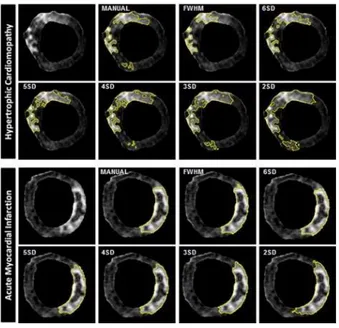
A second common fixed-model approach is the full-width half maximum (FWHM) approach, where half of the maximum intensity within a user-selected hyper-enhanced region is user-selected as the fixed intensity threshold. For the task of obtaining the mean intensity of viable tissue, the user selects a ROI of viable myocardial tissue. An example of the results obtained applying different approaches in reported in figure 3.
This analysis in clinical practice is usually performed in a 2D LGE-CMR short-axis view.
Figure 3. LGE analysis of a single short-axis acquisition and scar quantification using 7 different techniques in hypertrophic cardiomyopathy (top panel) and acute myocardial infarction (bottom panel).
22
1.4 Aim of this thesis
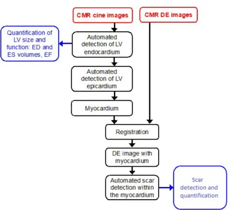
The aim of this thesis is the development and implementation of a segmentation workflow for the quantification of cardiac function in 3D domain, the extraction of significant clinical indexes such as EF, EDV and ESV, volume-time curves and myocardial scar burden. For this task the following segmentation workflow was developed to addresses these specific aims in 3D CMR datasets (Figure 4):
identification of the myocardium, including the endocardial (interior) and epicardial (exterior) boundaries;
registration of the cine CMR images in the LGE reference;
automatic delineation and quantification of the scar tissue within the detected myocardium.
23
Figure 4 Proposed workflow for scar detection and quantification from cine CMR and LGE images.
24
Chapter 2
Segmentation of the left ventricle
chamber
This chapter describes a semi-automated approach for the quantification of the left ventricle chamber volumes from cine CMR images. Manual tracing of CMR images is the golden standard for the quantification of left ventricular function. However manual segmentation of the endocardium and epicardium boundaries has proven to be a subjective and time-consuming task. Automatic approaches are already on-board on MR system to support radiologist’s work, but results require heavy manual corrections. In this chapter the developed tool is presented, this chapter is based on the article “An automated approach for the 3D dynamic segmentation of the myocardium from magnetic resonance imaging” by Fabbri C., Kawaji K., Nazir N., Patel A., Mor-Avi V., Corsi C
25
2.1 Introduction
Cardiovascular diseases are the leading cause of mortality in Western countries: The Global Burden of Disease estimates that 29.6% of all deaths worldwide (15616.1 thousands death) were caused by cardiovascular diseases in 2010. Among these stroke and coronary heart disease, in which arteries supplying blood to the heart muscle (myocardium) eventually leads to a heart attack (or myocardial infarction), is responsible for 12% of all deaths.
One of the most important technological developments of the last several decades which significantly contributed to early detection of heart disease is the use of noninvasive cardiac imaging, including a growing number of imaging modalities capable of depicting different aspects of cardiac anatomy and physiology.
Nowadays, CMR has already been proved to be and accurate tool for the quantification of the ventricular chamber volumes and the assessment of cardiac diseases. By allowing the acquisition of the cardiac chambers with increasingly high in-plane spatial and temporal resolution, it minimizes problems such as geometric assumptions, foreshortening. However, it suffers of some issues associated with partial volumes, spacing between slices and metallic artefacts.
In clinical practice, all the available commercial tools require user input for the selection of anatomical landmarks, initialization or tracing of LV boundaries. All these tasks are both quite time-consuming and rely on the user experience to include papillary muscles and other structures, with
26
potential effect on the accuracy of calculated cardiac indexes. Therefore, the development of automated image analysis techniques that overcome these limitations and allow fast and fully automated, accurate quantification of these parameters without the need for operator intervention, is highly desirable.
As of today, a variety of methods have been proposed to achieve a full segmentation of the ventricular chamber in CMR [17] [18] [19], usually by analyzing images slice by slice and frame by frame [20] [21]. Very few studies faced the issue of the most basal slice which is entirely included in the final surface for volume quantification, potentially resulting in volume overestimation.
To overcome the limitations of two-dimensional segmentation models, we designed and implemented a new approach based on a dynamic three-dimensional level-set formulation for automatic endocardium and epicardium surface detection. As a preliminary step, in this study, we validated the endocardium segmentation by comparing our estimates of end-diastolic, end-systolic volumes and ejection fraction against the ones derived by manual tracings of an expert radiologist.
27
2.2 Material and methods
2.2.1 CMR imaging and population
Data from 25 patients (18 males, mean age: 61±12 years) with heart failure, which already underwent CMR imaging for the assessment of heart function and scar burden were analyzed. Short-axis, 2-chamber, 4-chamber and 3-chamber ECG gated sequences were used; the sequences were acquired using a Philips 1.5 Tesla scanner.
The acquired image pixel spacings were ranging from 0.5 to 0.7 mm; moreover, for the short-axis sequence, spacing between slices was 10 mm and slice thickness was 6 mm. Temporal resolution was 30 frames per cardiac cycle.
Cine CMR data were obtained from the Cardiac Imaging Laboratories at the University of Chicago Hospitals, these data were acquired using a Philips Scanner running at 1.5 Tesla. Reference measurements were obtained by manual tracing performed by an expert, using an in-house developed software package. LV trabeculations and papillary muscles were included within the left ventricle cavity, according to the American Society of Cardiologist guidelines.
28
2.2.2 Image Processing
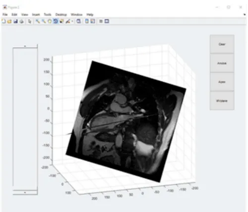
To constrain the segmentation inside the boundaries of the LV chambers a moving mitral valve (MV) plane was generated and the position of the apex was specified inside a three-dimensional rendering of 2-Chamber and 4-Chamber views of the heart.
To generate the MV plane a set of at least three points was selected in the End-Diastole and End-Systole frames, every point in the ED is associated with another one in ES and then the position is interpolated during the cycle.
Then for every frame the plane that minimizes the distance between the set of points is calculated.
For the detection of the endocardial boundaries a probabilistic level set was applied [22].
𝐸(𝜙) = − log 𝑝 (𝐼) 𝐻(𝜙) 𝑑𝑥 − ∫ log 𝑝 (𝐼) 1 − 𝐻(𝜙) 𝑑𝑥 − 𝐿 𝐻(𝜙) + |∇ 𝐻(𝜙)|𝑑𝑥
29
E(𝜙) is an energy function which is minimized during the evolution of the level set, H(𝜙) is the Heaviside function and, and p1 and p2 are the pixel
intensity distributions of object and background. The model is initialized on all the planes between the MV plane and the apex, using and ellipsoid centered whose main axis is defined by the intersection of the 2-Chamber view plane and the 4-Chamber view. The differential equation that drives the level-set model considers the different resolution in the perpendicular direction (which is the spacing between slices) and inside the plane (given by the image pixel spacing).
Figure 5 Three-dimensional rendering of 2-Chamber and 4-Chamber views of the heart for the selection of anatomical landmarks
30
Since the probabilistic model output not only detects the desired region of the LV but also other neighboring objects of similar intensity (such as the right ventricle), a series of morphological operator and connectivity checks were applied to the segmentation.
First every unconnected region was erased, then the center and size of the segmented region were calculated in each plane and if the difference between following frames was too big the segmentation was adjusted using the mask obtained from the previous frame, then a regularization step using curvature flow was applied to smooth the resulting boundaries.
The resulting segmentation is then used to initialize the level-set model in the following frame, cutting the time needed to reach the end of the level-set evolution.
After the segmentation of the endocardium boundaries is completed, a Malladi-Sethian level-set model [6] is applied to detect the epicardium:
0
tF
where 𝜙 corresponds to the level-set function.
The force F which drives the evolution of the level-set function was defined as:
where the three terms correspond to an expansion/contraction term, a curvature term (for regularization) and an advection term respectively.
g g g F
31
The function g is an edge indicator and its gradient corresponds to a motion field that guides the evolution of the level-set towards the boundaries of the anatomical structure:
The level-set function used as initial condition for the model is obtained by reinitializing the previously obtained contours and adding an offset to ensure that the solution adheres to the epicardium boundaries.
Statistical analysis was performed using Excel, Correlation Analysis was conducted for the End-Diastolic Volume, End Systolic Volume and the Ejection Fraction. 2 ) ( * 1 1 I x G g
32
2.3 Results
The tool for dynamic volume and mass quantification from was developed and implemented in MATLAB and tested on a laptop with an i7-7600M Processor with 16 GB of Ram.
Time required for the segmentation of a full Cine sequence depends on its size and on the number of frames acquired. Average time for a data set of 40 frames, 10 slices and 200 voxel side was about five minutes.
End-diastolic and end-systolic volumes measured from conventional semi-automated tracings ranged widely from 78 to 176 ml and from 48 to 124 ml, respectively, reflecting the inhomogeneity of the study group.
Two qualitative examples of the results obtained in one patient are reported in Fig. 6 and 7.
Figure 6. Endocardial (red) and epicardial (green) contours detected at ED (left) and ES (right) on a slice at the mid level of the left ventricle
33
Figure 7. Three-dimensional rendering of detected endocardial (red) and epicardial (surfaces) in the CMR volume
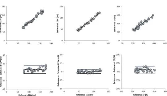
In Figure 8 there are the resulting graphs with linear regression and Bland-Altman analysis between the proposed algorithm and a manually traced reference for EDV and ESV.
Linear regression analysis between the proposed approach and the reference volume values resulted in very good correlation coefficients and regression slopes near 1.0 for both end-diastolic and end-systolic volumes (EDV: r=0.99, y=0.9x+15.3; ESV: r=0.94, y=1.0.x+2.7). LV ejection fraction resulted in a correlation coefficient of r=0.91, y=0.85x+0.1).
34
Bland-Altman analysis shows small biases between the computed parameters and the reference technique for EDV, ESV and EF (bias: 7.9 ml; 0.8 ml and 4% respectively). These biases reflected systematic errors of 6.0%, 1.0% and 10.3% of the corresponding mean values. The 95% limits of agreement were relatively narrow (EDV: 9.7 ml, ESV: 8.8 ml, EF: 10%).
Figure 8. Regression analysis (top panels) and Bland-Altman plot (bottom panels) of EDV (left) , ESV (middle) and EF (right).
35
2.4 Discussion and conclusion
The proposed algorithm allows a faster quantification of the LV chamber volume throughout the cardiac cycle compared to the time-consuming manual measurements limited to end-diastolic and end systolic frames for cardiac function evaluation. Importantly the proposed approach makes available volume-time curves thus allowing diastolic and systolic function in addition to ejection fraction.
Moreover, the proposed approach provides a solution for partial volume error correction, through the definition of a moving MV plane which eliminates the need for subjective slice selection and ensuing errors in LV volume measurements.
Validation of the new designed approach against volumes derived from manual tracings from expert cardiologist’s shows promising results for EDV. ESV quantification showed lower levels of agreement probably because of a partial volume effect affecting reference ESV values, in which the basal slices are entirely considered. Consequently, also EF suffers from the same potential issue.
In the next chapter, the three-dimensional models will be integrated with data from other sequences already available, such as delayed enhancement or fast strain encoding ones to allow further analysis of the cardiac
36
Chapter 3
Cine-LGE registration and scar
quantification
This chapter describes the approach used to superimpose the reconstructed LV myocardium boundaries in the LGE reference frame, to apply the previously described quantification algorithms for the quantification of myocardial scar tissue.
3.1 Introduction
LGE–CMR is the gold standard for assessment, risk stratification and treatment of AMI and CMI patients, through the detection, characterization quantification of myocardial scar tissue, which is considered an indicator of residual cardiac function. To assist the cardiologist in the post-intervention and long-term CAD management [23], an automated approach for 3D quantification of the scar tissue extent and its characterization was
37
developed. For this purpose, LGE-MRI data were acquired on the patients and the grey intensity levels were superimposed on the reconstructed 3D LV model obtained segmenting the cine CMR images finally, different methods were used for the fibrosis quantification and compared.
3.2 Material and methods
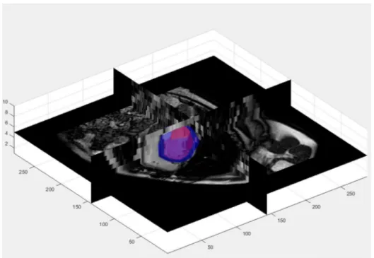
The LGE-CMR data were acquired with the same scanner used for the cine CMR acquisitions using 3D MP-inversion recovery with fat saturation. The images were acquired 15 min after contrast injection. An example of the LGE-CMR image is shown in the Figure 9 (top left). The structural example of an acquired LGE-CMR image. remodeling information derived from LGE-CMR data was superimposed on the 3D LV model applying a multimodality affine registration on the data based on mutual information (MI) as a similarity measure.
3D cine CMR images were registered on the spatial domain of 3D LGE images, the estimated affine transformation matrix was then used to register the three-dimensional myocardium geometry in the LGE-CMR spatial domain [24].
The SI from the extracted myocardium region obtained by the LGE-CMR images was used to obtain information on scar quantification.
38
Figure 9. 2D example of the registration between an LGE image (top left) and the corresponding cine CMR image (top right); an automatic crop (bottom left) based on the myocardium location is used for the registration of the two volumes the registered images are shown in the bottom right panel
The last step of the implemented workflow regards the fibrosis quantification. FWHM and n-SD techniques were employed. For each slice the scar area was extracted; the volume of the scar in 3D was obtained by applying the method of disks.
Data from 12 patients were analysed, to evaluate the performance of the two proposed approaches.
An expert radiologist manually traced the scar tissue on each slice. To evaluate the performance of the two approaches the overlapping between
39
the reference area manually traced and results from the two different implemented algorithms were compared using Dice Index. The ratio between the extracted scar volumes ( Vscar / Vscar-ref ) .
3.3 Statistical analysis and results
For the given results, analysis of the similarity of the measurements of volume was done, confronting the ground truth from the reference to the output of the different methods. To ensure that noise coming from hyper isolated pixel all regions with a surface lower than 5% of the myocardium in each slice were excluded.
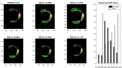
The results obtained from 5SD, 6SD and FWHM were comparable, since the threshold obtained were similar.
From the application of the methods, it’s easier to note that when the infarcted zone is well enhanced, there is a clear distinction between healthy tissue and scar, obtaining higher Dice Coefficient scores as show in the figures above. Often, we achieve a better overlapping between the reference scar volume and the volumes obtained with higher threshold, (5-6 SD and FWHM) gradually reaching the reference volume of the scars. Higher thresholds lead to higher accuracy and gradually exclude noise, in cases where the images are not well enhanced, due to the short time between contrast agentinjection and acquisition. In this case the resulting image intensity is homogeneous and there is no clear distinction between
40
infarcted and healthy tissue. The automated methods using SD fail since the detected threshold may be higher than the maximum image intensity. Four different examples of the results obtained in four different patients are reported in the following figures.
In the Table 1 and 2 results regarding the Dice coefficients and the volume ratio are reported.
Figure 10. Scar detection results in slice #5, pt.27, applying the different approaches, (reference GT in red, automated approaches in green); scar volumes obtained applying the different approaches are reported on the right panel.
41
Figure 11. Scar detection results in slice #21, pt.27, applying the different approaches, (reference GT in red, automated approaches in green); scar volumes obtained applying the different approaches are reported on the right panel.
Figure 12 Scar detection results in slice #16, pt.57, applying the different approaches, (reference GT in red, automated approaches in green); scar volumes obtained applying the different approaches are reported on the right panel.
42
Figure 13 Scar detection results in slice #14, pt.89, applying the different approaches, (reference GT in red, automated approaches in green); scar volumes obtained applying the different approaches are reported on the right panel.
Table 1 Dice coefficients between reference volume and the proposed methods.
1 2 3 4 5 6 7 8 9 10 11 12 FWHM 0,49 0,53 0,61 0,56 0,54 0,55 0,57 0,56 0,55 0,56 0,56 0,56 2SD 0,30 0,51 0,39 0,33 0,36 0,41 0,38 0,37 0,37 0,39 0,38 0,37 3SD 0,38 0,54 0,48 0,43 0,44 0,48 0,46 0,45 0,45 0,46 0,46 0,46 4SD 0,47 0,57 0,56 0,50 0,51 0,54 0,53 0,52 0,52 0,53 0,53 0,52 5SD 0,53 0,60 0,63 0,56 0,57 0,59 0,59 0,58 0,58 0,58 0,59 0,58 6SD 0,57 0,61 0,64 0,53 0,58 0,59 0,59 0,57 0,58 0,58 0,58 0,58
43
Table 2 Volume ratios between the proposed methods and the reference volumes.
1 2 3 4 5 6 7 8 9 10 11 12 FWHM 1,03 1,14 1,54 1,50 1,29 1,32 1,42 1,41 1,35 1,36 1,39 1,38 2SD 5,02 2,12 3,25 4,53 4,08 3,36 3,64 3,96 3,85 3,67 3,74 3,82 3SD 3,26 1,89 2,43 2,71 2,71 2,39 2,51 2,59 2,58 2,51 2,53 2,56 4SD 1,94 1,69 1,91 1,96 1,90 1,84 1,89 1,91 1,89 1,88 1,89 1,89 5SD 1,33 1,50 1,39 1,48 1,42 1,45 1,43 1,45 1,44 1,44 1,44 1,44 6SD 1,02 1,32 1,10 1,20 1,14 1,20 1,16 1,18 1,17 1,18 1,17 1,17
3.4 Discussion and conclusions
From the analysis and evaluation of the results from automated methods we reach some of the conclusion already present in literature. The comparison with the gold standard shows that even if there is a good overlap of the myocardial mask the limitations posed by a simple thresholding are not able to replace manual tracings in order to characterize the scars, but there is room of improvement with the development of more complex and new methods to analyse the already segmented myocardium. The SD approach has reproducibility issues, since the thresholds depends on the selection of a small patch of healthy tissue, while FWHM is less affected. In conclusion new approaches to exploit and differentiate grey zones from infarct core will be needed, in order to characterize viable and non-viable myocardium in order to become a real asset in clinical practice.
44
Chapter 4
Left atrium fibrosis quantification
Projects related to left atrium have also been conducted during my PhD activities.
This chapter describes the techniques and tools developed for an automated detection of left atrium (LA) and LA fibrosis from LGE-CMR images. In the first paragraph the approach based on a convolutional neural network is described for the segmentation of the left atrium. In the second paragraph different techniques are applied and compared to assess and quantify the extent of fibrotic tissue in the LA.
4.1 Left atrial volume quantification
The first part of the chapter is based on the article “A semantic-wise convolutional neural network approach for 3-D left atrium segmentation from late gadolinium enhanced magnetic resonance imaging” by Davide Borra, Alessandro Masci, Lorena Esposito, Alice Andalò, Claudio Fabbri, and Cristiana Corsi
45
4.1.1 Introduction
Atrial fibrillation (AF) is the most common arrythmia worldwide. It has been estimated that the prevalence of AF in US is about 2.2 million including paroxysmal or persistent AF. There are about 160,000 new AF cases each year in the US and in the European countries alone. Consequences of AF could imply a notable reduction in quality of life, poor mental health, disability, dementia and mainly an increment of the stroke risk five-fold. Radio frequency ablation (RFA) of the left atrium (LA) represents the therapy for AF patients where antiarrhythmic drugs and direct current cardio-version show no efficacy. Despite huge improvements for targeting and delivery of AF ablation, the long-term durable restoration of sinus rhythm is achieved only for a part of AF patients. Indeed, AF-free rates after a single ablation vary between 30 and 50% at 5 years follow-up. The low success of the current AF treatment could be related to the incapability to define a personalized approach for ablation, also including atrium specific anatomy and fibrotic tissue location. Late gadolinium enhanced magnetic resonance imaging (LGE MRI) is a new emerging non-invasive imaging acquisition which might be employed for the assessment of LA myocardial tissue in patients affected by AF. With this technique, healthy and scar tissues are differentiated: scar tissue is visualized as a region of enhanced or high signal intensity while healthy tissue is characterized by low signal intensity. For this purpose, several clinical
46
studies suggested that the information on LA scar tissue can provide relevant information for the assessment of the appropriate strategy in catheter ablation; moreover, fibrotic changes in the LA substrate have been proposed to explain the persistence and sustainability of AF. Through LGE MRI, the detection of the fibrotic tissue to identify native and post-ablation atrial scarring is provided and this might imply an improvement of the success rate of the RFA. However, in clinical practice the detection of the LA anatomy from LGE MRI is a very challenging task, given the complexity of the atrial and pulmonary veins (PVs) structures and the limited contrast of this imaging acquisition technique. Indeed, the thickness of the LA wall is very low. Other potential sources of error are the residual motion due to patient breathing, heart rate variability, low signal-to-noise ratio, and contrast agent washout during the long acquisition which results in a reduction of the image quality.
Several studies aimed at LA anatomy and fibrotic tissue assessment from LGE MRI showed promising results. However, most of them were based on manual segmentation of the LA wall and PVs. This implies a time-consuming subjective task, resulting in a poor reproducibility between multicentre studies. Therefore, the availability of a fully automatic algorithm for LA chamber segmentation would be very useful to accurately reconstruct and visualize the atrial structure for clinical use. To this purpose, the use of convolutional neural networks (CNNs) represents a suitable approach for the LA+PVs segmentation. Recently, Mortazi et al. developed a 2-D convolutional neural network (CNN) approach for the LA+PVs segmentation from cine MRI SSFP sequences and CT data
47
(STACOM 2013 Cardiac Segmentation Challenge) and Baumgartner et al. proposed a fully automated framework, combining U-Net and batch normalization, for the segmentation of the left and right ventricles from short-axis cardiac cine MRI data, training the network in 2-D and 3-D. The aim of this work was the design and development of an automatic image segmentation algorithm of the LA cavity from LGE MRI based on the use of CNNs, exploiting a deep learning pipeline based on the successful architecture UNet. The network was trained end-to-end from scratch using 3-D data available in the training phase of the STACOM 2018 Atrial Segmentation Challenge
4.1.2 Methods
One hundred cardiac LGE MRI data with ground truth labels and 54 LGE MRI data without ground truth labels were provided by the organizers of the STACOM 2018 Atrial Segmentation Challenge during the training and testing phases, respectively. The original resolution of the data is 0.625×0.625×0.625 mm. To train the model looking at the performance on unseen data during the optimization, we manually split the dataset in a training (80%) and a validation set (20%).
Let X(i) be the i-th MRI data and Y(i) its true binary segmentation (0 background, 1 LA) i ∈ [1, 100]. X(i) and Y(i) have the same size of m × n × d, where m and n are 576 or 640 and d is 88. Then, a 3-D crop containing LA of m1 × n1 × d1 = 320 × 384 × 88 for each image and mask is
48
extracted, generating X(i)c and Y(i)c (cropped data and masks). The
assessment of the coordinates of this crop is obtained by applying a rough segmentation based on Otsu’s algorithm to each middle axial slice of the entire dataset.
Considering that LGE MRI images are acquired in the axial plane applying a standard protocol which always considers the LA chamber in the centre of the acquired image and the results of the rough segmentation, LA is easily located, and the images are consequently cropped. Once the crop is extracted, a subsampling procedure is performed to reduce the computational cost.
according to the available hardware; in this way X(i)sc and Y (i)sc are
generated (subsampled cropped data and masks). The subsampled region of interest size is 144 × 176 × 32 and the network is trained with these 3-D data.
In the following the CNN architecture, regularization techniques and loss function optimization are described (Figure 14).
CNN architecture in order to perform the LA segmentation task, we introduced a deep learning approach based on the U-Net architecture. In the convolutional layers, kernel size of 3 × 3 × 3, stride size of 1 × 1 × 1 and Rectified Linear Units (ReLUs) activation functions in the hidden layers or sigmoidal activation function in the output layer are used. In the max pooling layers, a pooling size of 2 × 2 × 2 and stride size of 2 × 2 × 2, halving the shape of hidden activations, are employed. Lastly, in the transposed convolutional layers, kernel size of 2×2×2 and stride size of 2×2×2. For both convolutional and transposed convolutional layers,
49
padding size is such that the output shape of the layer is the same of the input shape. Furthermore, biases and weights are randomly initialized from a truncated normal distribution and using the initialization scheme proposed by He et al. for ReLUs, respectively.
Regularization techniques in order to introduce a regularization effect, batch normalization and early stopping techniques are employed. The first one is an adaptive re-parametrization introduced to reduce the covariance shift and it also acts as regularizer. These normalizing layers are included after each hidden convolutional layer and immediately before the activation function. Lastly, we employed the early stopping technique, that consists in returning the model with lowest validation set error during the training and stopping the optimization.
Loss function optimization During the training a Dice coefficient (DC) based loss function, named Dice loss, is computed. Let dc be the Dice coefficient computed between the true mask and the predicted mask; the Dice loss is defined as dl = 1 − dc. In order to solve the optimization problem, the Adam adaptive learning rate optimization algorithm [19] is used. Exponential decay rates β1 and β2 are 0.9 and 0.999 respectively, while the learning rate is 1e-4. Lastly, a max number of epochs of 255 with a batch size of 2 is used.
Once the training is completed, the CNN is fed with an unseen input X (i) sc and the model directly produces the 3-D segmentation P(i)sc. During the
prediction step, at first the model predicts the segmentation P(i)sc of the i-th
image subsampled crop X(i)sc , then the final 3-D predicted segmentation
50
size m1 × n1 × d1 and by padding this intermediate result P(i)c with zeros
to the i-th input original size m × n × d. Then, a removal procedure based on the evaluation of the connected-regions volume is applied, generating the final mask P(i)la.
Since the obtained segmentation P(i) sometimes contains LA spurious elements, only the biggest volume associated with the LA is kept. The procedure described in this section was applied on the validation and test sets. Furthermore, it was also applied on the validation set during the optimization process to use the early stopping technique correctly.
51
52
4.1.3 Results
For the performance evaluation DC was used. In particular, DC were computed, and we obtained DCsc = 0.930±0.026, DC = 0.910±0.029 and
DCla = 0.911±0.028 (mean value ± standard deviation) on the validation
set. The spurious regions removal step was necessary for only 3 of 20 predicted validation masks. Considering the small size of the spurious regions and the low number of images post-processed with this procedure, after this step the performance did not improve significantly (on average from 0.910 to 0.911). Two examples, in Fig 15, of the 3-D validation data segmentation obtained with 3-D U-SWCNN, comparing P(i)la (red) and
Y(i) (blue), are reported. These two examples correspond to the best and the worst predictions of the neural network with DC = 0.964 and DC = 0:850, respectively. Lastly, an example of a 3-D validation data segmentation in which the CNN is able to reconstruct all the PVs even if some of them are not included in the ground truth is reported. During the final testing phase only, the average Dice coefficient was provided by the organizers and it was DC = 0:949.
53
Figure 15 Best and worst case of the LA segmentation, in red the proposed CNN, in blue the ground truth
54
4.1.4 Conclusions
The proposed method produces a joint segmentation of the LA and PVs in AF patients. Despite the high variability of the LA anatomy and the subsampling procedure applied, the model provides an accurate mask that could be useful for ablation therapy planning. In addition, a mapping of grey level intensities of LGE MRI on the 3-D LA anatomy would make directly available a 3-D model of fibrotic tissue distribution on LA surface. Some ground truth masks included PVs (see Fig. 5). Therefore, the 3-D U-SWCNN was trained using data in which sometimes PVs are annotated and sometimes they are not. This is the reason why the network sometimes can recognize them in data in which they were not annotated in the ground truth. This leads to an additional source of error in the evaluation metric. Future development will include:
training the network with 3-D data with a smaller subsampling ratio in order to exploit original information, hopefully leading to a higher DC and in order to reduce the gap between DC and DCsc
introduction of a new loss function
separation of the PVs structures from the joint segmentation of LA+PVs and evaluation of the Dice coefficient of the LA chamber without the PVs.
55
4.2 Fibrotic tissue assessment in left atrium
Atrial fibrillation (AF) is the most common sustained arrhythmia [26] and several studies have demonstrated that AF is associated with electrical and structural remodelling in the left atrium (LA) which was proven to sustain the arrhythmia [27],[28].
Focusing on structural remodelling, late gadolinium enhanced magnetic resonance imaging (LGE-MRI) is a recent technique used for LA fibrosis localization and quantification in the LA wall. The DECAAF study [29] reported that extent of fibrosis in the LA in AF patients may predict recurrences after the ablation procedure. In [30] patients were divided into 4 categories depending on fibrosis extent: Utah stage 1 or minimal fibrosis (<5% enhancement), Utah stage 2 or mild fibrosis (5–20% enhancement), Utah stage 3 or moderate fibrosis (20–35% enhancement) and Utah stage 4 or extensive fibrosis (greater than 35% enhancement). Based on this scoring different therapeutic approaches were suggested, including pulmonary vein isolation for patients in Utah score 1 and 2, pulmonary vein isolation and linear lesions in the LA posterior wall for patients in Utah score 3, ablation of the atrio-ventricular node and biventricular pacing for patients in Utah score 4. Therefore, the information about the fibrosis extent may help the electrophysiologist in patient’s selection for the ablation procedure.
Despite these promising results, assessment of fibrosis from LGE-MRI in AF patients has not been adopted in the clinical setting due to scarce result
56
reproducibility [31,32] mainly due to the absence of a standardized image processing protocol to quantify fibrosis extent. Therefore, the aim of the study was to compare different methods to quantify fibrosis in the LA in the 3D domain.
4.2.1 Materials and Methods
4.2.1.1 Clinical Data
LGE-MRI from 60 AF patients acquired at the CARMA Center (University of Utah) in which manual tracing of LA wall by expert radiologist was available, were analyzed [33].
All patients underwent MRI studies on a 1.5-T Avanto clinical scanner (Siemens Medical Solutions, Erlangen, Germany) using a TIM phased-array receiver coil or 32-channel cardiac coil. LGE-MRI was acquired 15 minutes after the contrast agent injection (dose, 0.1 mmol/kg body weight; Multihance, Bracco Diagnostic Inc, Princeton, NJ) using 3-dimensional inversion-recovery-prepared, respiration-navigated, ECG gated, gradient-echo pulse sequence with fat saturation (voxel size of 1.251.252.5 mm, flip angle of 22°, TR/TE=6.1/2.4 ms, IT=230 to 320 ms, parallel imaging with GRAPPA technique with 2 and 42 reference lines. Typical scan time for the DE-MRI study was 5 to 9 minutes, depending on the subject’s respiration and heart rate.
57
4.2.1.2 LGE-MRI Data Processing
Five different approaches for fibrosis segmentation were applied in this study.
Thresholding techniques included a histogram-based reference, a blood-pool-based reference and the image intensity ratio technique [32]. All these approaches required a reference value Ref obtained from a region of interest (ROI):
Th = Ref + N∙SD
where Th is the threshold that separates scar tissue from healthy tissue, SD is the standard deviation in the selected ROI, N is the number of SDs. In the histogram-based reference approach (H-6SD), normal tissue is defined as the mean of the pixel intensities between 2 and 40% of the maximum intensity within the atrial wall (M2-40%). The threshold ThH-6SD
was computed at 6SD (SD2-40%) above the mean of normal tissue:
ThH-6SD=M2-40% + 6SD2-40%
In other approaches, the ROI is located in the blood pool (BP) [34]. In this case the threshold was computed using the mean (MBP) and standard
deviation (SDBP) of the pixel intensities inside the blood pool region:
58
where ILA is the myocardial intensity of the LGE-MRI in the LA wall.
In the image intensity ratio approach (IIR), the threshold is computed by normalizing the myocardial image intensity by the mean blood-pool intensity:
ThIIR= ILA/MBP
Two additional techniques were based on the Chan-Vese (CV) and on a graph-cut (GC) models.
The CV approach [35] finds in the image the two regions characterized by the maximum difference in grey scale by minimizing the following energy function F:
𝐹(𝐶) = |𝐼(𝑥, 𝑦) − 𝑐 | 𝑑𝑥𝑑𝑦
( )
+ |𝐼(𝑥, 𝑦) − 𝑐 | 𝑑𝑥𝑑𝑦
( )
where I is the image and c are the mean intensities inside and outside the evolving curve C.
In the graph based approach [36] the source and sink nodes were modeled as healthy and fibrotic tissue voxels. The energy function to be minimized was defined considering a regional term Rx and a boundary term Bx,y
equally weighted (λ=0.5) where X are the nodes and A the relationships between two adjacent voxels:
59
𝐹(𝐿) = 𝜆 𝑅 (𝐿 ) + (1 − 𝜆) 𝐵 , 𝐿 , 𝐿
( , )
The LA wall was modeled using two Gaussian functions representing the two classes, healthy myocardium (𝜇 , 𝜎 ) and fibrotic tissue (𝜇 , 𝜎 ). The regional term was defined as:
𝑅 (ℎ𝑒𝑎𝑙𝑡ℎ𝑦) = − ln 𝑃(ℎ𝑒𝑎𝑙𝑡ℎ𝑦|𝐼 ) = −𝑙𝑛 𝜋 𝑁(𝐼 |𝜇 , 𝜎 ) 𝑝(𝐼 )
𝑅 (𝑓𝑖𝑏𝑟𝑜𝑠𝑖𝑠) = − ln 𝑃(𝑓𝑖𝑏𝑟𝑜𝑠𝑖𝑠|𝐼 ) = −𝑙𝑛 𝜋 𝑁(𝐼 |𝜇 , 𝜎 ) 𝑝(𝐼 )
where Ix is the intensity of the voxel x, 𝜋 represents the ratio of the two
classes, 𝜇 are the mean and 𝜎 the covariance matrix of the two Gaussian models; N(∙) describes the probability Gaussian function and p(Ix) is
𝑝(𝐼 ) = 𝜋 𝑁(𝐼 |𝜇 , 𝜎 )
The boundary term was defined as:
𝐵 , 𝐼 , 𝐼 =𝑒
60
where Ix and Iy are the intensity of the voxel x and of its neighbour y; 𝛽 is a
penalty term which was set equal to 5 to give more weight to high gradients between voxels belonging to different classes; dist(x,y) is the Euclidean distance between the two voxels x and y. Minimizing the energy function F(L) leads to the partition of the graph in two regions corresponding to healthy and fibrotic tissue.
All LGE-MRI slices were analysed for each patient by considering the LA wall manually traced by the expert cardiologist.
For each patient and for each technique we obtained the 3D model of the LA with visual localization of fibrosis. For each technique we quantified the percentage of fibrosis with respect to the entire LA wall mass.
4.2.3 Results
A qualitative example of the fibrotic tissue evaluated in the LA wall in one LGE-MRI slice applying the different quantification techniques is reported in Figure 15.
An additional example of the LA 3D models obtained in one patient applying the five different approaches and the corresponding percentage of fibrotic tissue are reported in Figure 16.
Overall, results showed these five approaches can be divided in two groups; the group composed by the H-6SD, CV and GC is characterized by similar results (mean coefficient of variation=0.3), while the results obtained applying BP and IIR strongly depend on the quality of the acquisition (mean coefficient of variation=0. 62).
61
Considering H-6SD technique as the reference approach, BP and IIR showed a negative and low correlation; GC and CV showed a positive and good correlation (Figure 17).
An example of Utah stage score obtained in one patient applying the different techniques for fibrosis segmentation is shown in Table 3. Utah stage classification resulted in a wide disagreement (22/60 patients, 37%) among BP and IIR. The two approaches which best matched the Utah classification were the CV and GC (49/60 patients, 82%)
Fig. 15: A qualitative example of the fibrotic tissue (green region) evaluated in the LA wall (blue region) in one LGE-MRI slice applying the different quantification techniques (BP: blood-pool-based reference; IIR: image intensity ratio; CV: Chan-Vese; GC: graph-cut; H-6SD: histogram-based reference).
Fig. 16: Example of the LA 3D models obtained in one patient applying the five different approaches and the corresponding percentage of fibrotic tissue (BP: blood-pool-based reference; IIR: image intensity ratio; CV: Chan-Vese; GC: graph-cut; H-6SD: histogram-based reference).
62
Table 3. Percentage of fibrosis obtained applying the five segmentation approaches and the derived Utah score and therapeutic indication in Patient #0937.
Fig. 17: Correlation analysis between % of fibrotic tissue obtained applying the different techniques. The H-6-sd was considered the reference technique (BP: blood-pool-based reference; IIR: image intensity ratio; CV: Chan-Vese; GC: graph-cut; H-6SD: histogram-based reference; p: correlation coefficient).
63
4.2.4 Discussion and Conclusion
This study confirmed the evaluation of the quantification method appears critical and further research is needed to define a satisfactory standard for the segmentation of atrial fibrosis.
BP and IIR use the blood pool region to normalize the intensity values on the LA wall; therefore, these techniques strongly depend on image quality. The LA cavity signal should be properly suppressed but unfortunately a standardized image acquisition protocol is not available. Its availability would improve the performance of methods based on blood pool reference values. H-6SD, CV and GC showed repeatable results.
In conclusion the choice of the approach to quantify fibrosis appears critical. Further research is needed to define a satisfactory standard in the segmentation of atrial fibrosis. In addition, there is a strong need for a standardized imaging protocol, especially for methods that exploit information from the blood-pool region.
64
Chapter 5
Concluding remarks and
future developments
In this doctoral thesis, a workflow for the evaluation of cardiac function from Cine CMR images, and the detection of myocardial scar was presented, to provide a fast tool for the quantification of clinical indexes useful in clinical practice.
In Chapter 2, a segmentation algorythm for the detection of endocardial and epicardial boundaries was presented. The implemented approach uses two different level sets in a three-dimensional domain, a moving mitral valve plane was defined to constraint the evolution of the model in the ventricle. It proved to be an effective tool for fast and reliable generation of 3D geometric models and the evaluation of clinical indexes. In Chapter 3, a registration based on MI maximization was employed to find the transformation matrix from the Cine CMR reference to the LGE and to superimpose the previously extracted myocardium on the DE images, in order to avoid the inclusion of the blood pool, and to extract a ROI useful for the detection and quantification myocardial scars.
65
In Chapter 4, approaches for the quantification LA volume and the extraction of patient specific models are shown, which could prove useful for the treatment and gaining insight on AF mechanism are shown.
The proposed workflow may be modified to be applied on the other heart chambers, to asses scars and fibrotic tissue in the whole heart.
66
Bibliography
[1] O. 2013, "Health at a Glance 2013: OECD indicators," OECD Publishing, 2013. [2] R. Jablonowski, D. Nordlund, M. Kanski, J. Ubachs, S. Koul, E. Heiberg, H.
Engblom, D. Erlinge, H. Arheden and M. Carlsson, "Infarct quantification using 3D inversion recovery and 2D phase sensitive inversion recovery; validation in patients and ex vivo," BMC Cardiovasc Disord, p. 13:110, 2013. [3] D. F. M., J. P., A. P., D. B. M., A. G., S. U., A. D., B. C., G. T., S. N. and Z. M.,
"MRI evaluation of myocardial viability," La Radiologia Medica, vol. 111, no. 8, pp. 1035-1053, 2006.
[4] L. T, M. WJ and D. PG, "Cardiac MRI for assessment of myocardial perfusion: Current status and future perspectives," Journal of nuclear cardiology, vol. 8, no. 2, pp. 207-214, 2001.
[5] M. D. Filippo, P. Julsrud, P. Araoz, M. D. Blasi, G. Agnese, U. Squarcia, D. Ardissino, C. Beghi, T. Gherli and M. Z. N. Sverzellati, "MRI evaluation of myocardial viability," La Radiologia medica, vol. 111, no. 8, pp. 1035-53, 2006.
[6] X. Chen, M. Lu, G. Yin, T. Zhao, X. Shao, R. Zhao, Y. Tang, J. An, S. Jiang and S. Zhao, "Three-dimensional phase-sensitive inversion-recovery Turbo FLASH sequence for the assessment of left ventricular myocardial scar in swine," PloS one, vol. 8, no. 1, 2013.
[7] G. Yin, S. Zhao, M. Lu, N. Ma, S. Zuehlsdorff, H. Cheng, S. Jiang, T. Zhao, Y. Zhang, J. An, C. Lv and Z. He, "Assessment of left ventricular myocardial scar in coronary artery disease by a three-dimensional MR imaging technique," Journal of magnetic resonance imaging: JMRI, vol. 38, no. 1, pp. 72-9, 2013. [8] A. Hennemuth, A. Seeger, O. Friman and H. Peitgen, "A comprehensive
approach to the analysis of contrast enhanced cardiac MR images," IEEE transactions on medical imaging, vol. 27, no. 11, pp. 1592-1610, 2008.