Journal of Energy and Power Engineering 9 (2015) 375-385 doi: 10.17265/1934-8975/2015.04.007
Cross-Validation of a Mobile N
2
O Flux Prototype (IPNOA)
Using Micrometeorological and Chamber Methods
Patricia Laville1, Simone Neri2, David Continanza2, Luca Ferrante Vero2, Simona Bosco3 and Giorgio Virgili21. EGC (Environnement et Grandes Cultures) Joint Research Unit, National Institute for Agriculture Research, Thiverval-Grignon 78850, France
2. West Systems L.L.C. (Limited Liability Company), Firenze 50126, Italy 3. Institute of Life Sciences, Advanced School Sant’Anna, Pisa 56127, Italy
Received: January 09, 2014 / Accepted: March 02, 2015 / Published: April 30, 2015.
Abstract: Within a LIFE+ project IPNOA (improved flux prototype for n2o emission from agriculture), LIFE11 ENV/IT/302 is a
mobile prototype was developed to evaluate at field scale N2O emissions using a fast chamber technique. Main challenge was to
develop a mobile system capable of moving on various field surfaces, equipped with very reliable N2O gas analyser (Los Gatos
Research Inc.), electrically autonomous (with batteries) and enough robust to face up to field conditions. In this paper, we report the major features of this prototype studied during two field campaigns. The N2O flux IPNOA prototype was compared with other
methodological implementations: first, during an INGOS (integrated non-CO2 greenhouse gas observing systems) campaign on a
grazed grassland at Easter Bush (Scotland) by Eddy correlation method, and then after on an arable crop at Grignon (France) using automatic and manual chambers fitted with QC-TILDAS (Quantum Cascade Tunable Infrared Laser Differential Absorption Spectrometer, Aerodyne Research Inc.), with the 46C model of thermo-instrument analyser or with a GC (gas chromatography) analysis.
Key words: Monitoring device, nitrous oxide inventory, agricultural managements, steady state chamber.
1. Introduction
In order to implement the European strategy on the reduction of greenhouse gas emissions of 20%-30% in 2020, an important decrease in the output of all these gases from their main sources is needed.
Agriculture is responsible in Italy for about 6% of total GHG (greenhouse gas) emissions in 2014 [1], with a main contribution by nitrous oxide (N2O) gas release from soil (i.e., 73%). Nitrous oxide emissions are mainly due to nitrogen fertilization in cropping systems. Nowadays, the total amount in N2O emissions for agricultural soil are mainly estimated by using the IPCC (Intergovernmental Panel on Climate Change) guidelines, reporting a simplified model involving the amount of fertilizer applied only and leaving out of
Corresponding author: Patricia Laville, doctor, research
field: evironmental sicences. Email: [email protected].
consideration other potentially important parameters [2], such as climatic conditions soil properties and agricultural managements.
N2O emissions are very difficult to evaluate, insofar magnitude of emissions are very variable spatially and temporally at field scale and all through the year.
The most common technique for assessing N2O fluxes on many crop plots at once is the steady state chamber [3, 4]. For the steady state chambers, N2O concentration changes are the most frequently estimated by both taking gas samples in small vacuum vials at different moments after closing the chamber and analyzing them thereafter using GC (gas chromatography) methodology. This involves many manipulations: making the vacuum in the vials, collecting the samples in the field after closing the chamber, ensuring the supply of carrier gas for the GC analysis, identifying and placing the tubes on an auto
D
Cross-Validation of a Mobile N2O Flux Prototype (IPNOA) Using Micrometeorological and Chamber Methods
376
sampler rack, performing calibration ranges for samples, formatting analysis. In addition, for each sample, the analysis lasts few minutes and limits the number of samples. The sensitivity of standard GC analysis is also weak, consequently to detect low emissions, it is the necessary to maintain chamber closed during large period of few tens of minutes (30-60 min) and can disturb the diffusion of biogas from the soil to the surface.
Developments of methodologies to improve inventories of these emissions are still needful. The LIFE+ IPNOA project fits perfectly within this requirement. Indeed, major objectives of this project were the developments of two prototypes for measuring N2O fluxes, the first “portable” to evaluate spatial variation on N2O emission at field scale for various crops and managements, the second “fixed” (the “station” prototype) to obtain the seasonal variations in emission.
This paper concerns only the field validation of the “portable” prototype. It was designed by WS (West System L.l.c.). To overcome the major inconvenient of steady chamber technique listed above, the prototype was equipped with on line continuous N2O analyzers, the sensitivity of the selected analyzer was enough to allow flux measurements over periods of 5 min. Compared to fast box system [5], the prototype was most “mobile” allowing measurements all across a field of several hectares or for contiguous fields. The prototype was designed to be in dependent in 230 VAC (volts of alternative current) power supply or generator.
The objective of this paper was to present the major characteristics of the IPNOA prototype and the results of a cross validation with various other methodologies previously used by INRA-EGC (Environnement et Grande Culture Joint Research Unit, National Institute for Agriculture Research). This validation was achieved during two experiments. The first was conducted in Scotland (Edinburgh) grassland during an INGOS (integrated non-CO2 greenhouse gas observing systems) campaign. The mapping of N2O emissions
obtained with the mobile prototype was compared with measurements of N2O fluxes using EC (Eddy covariance) methodology. The second experiment was conducted at Grignon (France) on barley crop. Performances of the prototype were then compared with other chamber designs (manual and automatic chambers). These campaigns were also an opportunity to test various features of the prototype.
2. Materials and Methods
2.1 Description of the Mobile Prototype
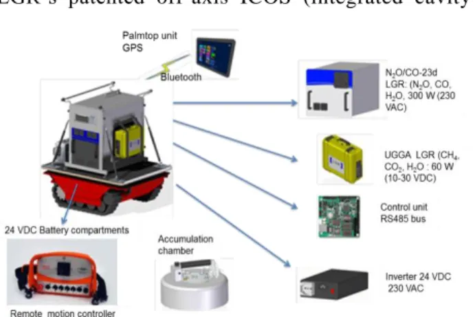
The instrumentation is arranged on a detachable unit placed on the light vehicle in order to separate the part dedicated to the traction from the part dedicated to the measurement. The vehicles itself hosts the batteries and the traction engines and in the upper part the control unit with gas analyzers (Fig. 1). These is two packs of batteries on dedicated to the vehicle engines (powered with 24 VDC (volts of direct current)), the other for the instrumentation.
The vehicle is equipped with remote motion controller. A joystick allows the control of the motion in all direction. The instrumentation is placed on platform fixed on the vehicle with silent block in order to dampen the vibration during the transport. The platform hosts two gas analyzers: N2O/CO (nitrous oxie, carbone monoxide) and UGGA (ultraportable greenhouse gas analyzer) analyzers developed by LGR (Los Gatos Research Inc.) [6]. These spectrometers use LGR‟s patented off-axis ICOS (integrated cavity
output spectroscopy) technology, a fourth generation cavity (http://www.lgrinc.com/analyzers/). The first one measures the N2O, CO and H2O gases and requires 300 W (powered with 230 VAC) in operation, the second measures CH4, CO2 and H2O and requires 60 W (powered with 10-30 VDC). AC (alternating current) power of 1,500 W for the instrumentation supply is delivered by an inverter of 24 VDC input from the battery pack. The battery packs are recharged by a battery charger box that will be connected to the power grid (230 VAC), when the prototype is not deployed in the field. The gas analyzers have several interfaces USB (universal serial bus), SERIAL (RS-232 standard), Ethernet ports. Output gas concentrations are given with a scan rate of 1 s.
A control unit operates/interrogates the various outputs of the instrumentation. The control unit is connected through bluetooth to a palmtop unit. The palmtop unit acquires and stores the measured values. The palmtop unit is equipped with a high performance GPS (global positioning system) allowing locating the chamber positions during its deployment.
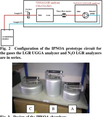
The two gas analyzers are connected in series according to Fig. 2. The LGR N2O has an internal pump (flow rate of about 250 cc·min-1). The sample inlet and outlet are 1/4 swagelok fittings. These ports will be connected to 2-4 mm (ID/OD (internal /external diameters)) teflon (or rilsan) tube. Twenty meters of tubes separate the inlet/outlet gas analyzers to the inlet/outlet accumulation chambers. Several chamber designs were tested during our cross validation (Fig. 3). All the chambers are equipped with a fan that mixes the headspace air during the measurement. The „C‟ chamber (V/A = 0.104 m) was the most used.
The entire device weighs about 600 kg and can be transported from on site to another at the rear of a van. A software “flux manager” installed on the palm pilot unit manages the start and the stop of the data acquisition during the chamber deployment. It is very interactive software, in real time, it is possible to
Fig. 2 Configuration of the IPNOA prototype circuit for the gases the LGR UGGA analyzer and N2O LGR analyzers are in series.
Fig. 3 Design of the IPNOA chambers.
A: area = 3.33 dm², volume = 2.9 dm3, V/A = 0.087 m; B: area = 3.40 dm², volume = 6.2 dm3, V/A = 0.211 m; C: area = 7.35 dm², volume = 6.65 dm3, V/A = 0.140 m. adjust the time interval to evaluate the rate of gas accumulation.
Gas emissions are deduced with concentration increase during the chamber deployments according a linear model Ci = bti + a. Ci denotes to the measured
concentration at time ti, b is the slope coefficient and a
is the intercept at ti = 0. Emissions are proportional of
the b coefficient and are estimated according to the following relationships:
b A V
Flux (1) The V/A corresponds to the ratio between the headspace volume and the area of the chamber.
1 2 1 n i i i n i i C C t t b t t
(2)A post treatment was performed according to two criteria. It must maximise the slope magnitude and the correlation coefficient, R2.
Two criteria were used to evaluate the quality of the
Cross-Validation of a Mobile N2O Flux Prototype (IPNOA) Using Micrometeorological and Chamber Methods
378
measurements: the coefficient of determination R² and the standard deviation of the slope coefficient—∆b using also to evaluate the standard deviation of the fluxes (Flux). Their analytical equations are the following:
2 1 2 2 1 1 n i i i n i i C bt a R C C
(3) b A V Flux (4) With:
2 1 2 1 1 2 n i i i n i i C bt a b n t t
(5)When the linear model Ci = bti +a fits well the data, R² is close to 1 and the ∆b/b ratio should be as small as possible.
2.2 Scotland Green Grass Experimentation: “Easter Bush” Site
The “Easter Bush” campaign took place during a N2O inter-comparison campaign of INGOS project. INGOS is an EU funded IA (integrating activity) project targeted at improving and extending the European observation capacity for non-CO2 greenhouse gases (http://www.ingos-infrastructure.eu/). To support this activity, the CEH (Centre for Ecology and Hydrology) in Edinburgh (UK) hosted an inter-comparison campaign for the measurement of micrometeorological fluxes of N2O on managed grassland for the period 3rd to 28th June, 2013. Measurements with IPNOA prototype were achieved during the last week of June 2013.
The Easter Bush measurement site is located in a rural area 10 km south of Edinburgh, Scotland UK (3°12‟ W, 55°52‟ N, 190 m a.s.l. (above sea level)). The site is situated on the border between two intensively-managed grassland fields of approximately 5 ha (hectare) each (Fig. 4).
The organic rich soil has consistently resulted in
high N2O emission factors from fertiliser application in previous studies. On June 11, 50 kg of nitrogen as NH4NO3 fertilizer form was applied. Eddy covariance methodology was mainly employed during this campaign. To inter-compare the instrumentations, the gas analysers belonging to the various participants were connected on a single EC acquisition chain (Table 1). Comparisons between instruments were very satisfactory and similar emissions were estimated with the various analyzers. Then, we compared only EGC-INRA measurements obtained by EC methodology with the dynamic enclosure method of IPNOA prototype. It was interesting to compare an “integrative” EC method with local measurements obtained with the mobile prototype.
The IPNOA chamber was deployed on the entire
Fig. 4 Easter Bush site.
Table 1 Instrumentation of Ester Bush campaign partners.
Country Institute Instrument Method Italy West system Srl N2O-LGR
Dynamic enclosure France EGC-INRA Aerodyne-QC
-TILDAS* Eddy covariance Finland FMI (Finnish Meteorological Institute) N2O-LGR Eddy covariance Finland University Helsinki N2O-LGR
Eddy covariance Denmark Technical University of Denmark Aerodyne-QC -TILDAS Eddy covariance Netherland ECN (Energy Research Centre Netherland) Aerodyne-QC -TILDAS Eddy covariance Unite Kingdom CEH Aerodyne-QC -TILDAS Eddy covariance QC-TILDAS*—quantum cascade tunable infrared laser
surface corresponding to the fetch of Eddy covariance measurements allowing evaluating the spatial heterogeneity in emissions.
Fig. 5 shows, for example, the localizations of IPNOA samplings during Easter Bush campaign on June 26.
2.3 Grignon Barley Experimentation
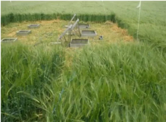
The cross validation at Grignon took place from the 1th to 12th July.The cross validation was provided in a field of 1 hectare close the EGC INRA building (Fig. 6) (48°50‟ N 1°56‟ E, 127 m a.s.l.). This field was sown early on March 2013 with spring barley. One hundred and twenty N·kg·ha-1 as NO3NH4 granule were applied early April. In July, the barley crop was very developed and we were away of the nitrogen application. To ensure good conditions for the cross validation, we cut barley and brought different doses of nitrogen as ammonium nitrate on different plots used as test areas.
Various implementations and equipment‟s were used during the cross validation: three automatically and three manually chambers were deployed on the field (Fig. 7). Performances of LGR N2O spectrometer
Fig. 5 Localization of the samples during Easter Bush campaign on June 26.
Fig. 6 Experimental site of Grignon.
of the mobile prototype were compared with other INRA gas analyzer: (a) a filter correlation spectrometer (46C Thermo Environment Inc.); (b) a GC (Varian CP3000), four certified cylinders of N2O calibration gases supplied by Air Liquid company were also used to test sensitivity in response of the LGR N2O analyzer and the response time of the of IPNOA chambers.
Three doses of nitrogen as ammo-nitrate granules were applied on the three manual and automatically chambers (i.e., 0 N: eq. 0 kg·N·ha-1, 50 N: eq. 50 kg·N·ha-1, 200 N: eq. 200 kg·N·ha-1) with an application of water for an equivalent of 20 mm of rainfall July 3 in the morning. A second irrigation was also achieved July 8 in the evening. The INRA automatically chamber setup were largely using during the NitroEurope project [7]. Gas analysis was achieved on line using a gas filter correlation N2O spectrometer (46C model of thermo environment). The sizes of chamber frames were 0.7 × 0.7 m² and were pressed into the soil at 7 cm, chamber height was 0.20 m. Commutation of a chamber to the next was achieved sequentially using various electro-valves. Deployment duration per chamber was 15 min with a complete cycle every hour. The scan rate for N2O concentration measurement was 10 s. During the cross validation, the Thermo 46C analyser was replaced by the N2O LGR to compare the responses of the two gas analysers on same soil area.
Fig. 7 Grignon devices with three manual chambers on left (area = 25 dm²) and three automatically chambers on right (area = 49 dm²). The height of chamber headspace was at mean 22.6 cm for the Auto chambers and 19.4 cm for the Manual chambers. INRA chambers differ on IPNOA chamber by their volumes and areas more wide. Their frames are inserted to a deep of about 7 cm into the soil.
380 The size o was 0.5 × 0 chamber he were collect through the (four sample were then s specifically of the cham analyzers.
3. Results
3.1 Compari Ester Bush Extensive prototype w than 30 loca (Fig. 6) to emissions. compared w the period identical ma the two me between day of variation: fluxes) were with IPNOA variability i lower for C CVs are con studies [7]. “hot spots” favorable, accumulatio denitrifiants 3.2 Compari Fig. 9 sho measured w obtained for magnitudes Cross-Vali of the frames .5 m². They w ight was als ted during 45 septum of th es per flux de subsequently adapted to c mber, the inpuand Discus
ison with Edde measurem were made on alization point o determine
IPNOA ch with Eddy cov
from June agnitudes of f ethodologies: ys 24, 25 and : ratio betwee e obtained (e. A chambers n N2O fluxe O2 fluxes on nsistent with n In the soils, where cond i.e., anoxic on of carbon .
ison with Grig
ows the com with Thermo 4 r the three a of emissions
dation of a M
for the three m were pressed t o 0.20 m. S min in vacuu he chamber li etermination) analysis by onnect during ut and the ou
ssions
dy Covariance ments with n large grill o ts on June 24 spatial vari hamber mea variance meas 24 to 26 (F fluxes were o : emissions t d 26. Large C en standard d .g., around 15 and indicate es. In compa nly around 30 numerous pre N2O product ditions for d zones whe and nitrogen gnon Automa mparison betw 46C and the I auto-chamber s obtained co Mobile N2O Flu and Ch manual cham to 5 cm deep Samplings of um tubes (12 ids every 15 . The air sam GC. On lid g the deploym utput of the L e Methodolog IPNOA mo f 1 ha with m , 25 and 26, 2 iability of N surements w surements du Fig. 8). Ove observed betw tend to decr CVs (coeffici deviation to m 50% on June d a large sp arison, CVs w 0%. These la eviously N2O tion is locate enitrification ere there is as substrates tically Chamb ween N2O flu IPNOA LGR r treatments. ontinuously w ux Prototype hamber Metho mbers , the f gas mL) min mples was ment LGR gy at obile more 2013 N2O were uring erall, ween rease ients mean e 26) atial were arges flux ed in n are s an s for bers uxes R and The with Fig. mea com foot gras Fig. ther by I arro was the valu and with It w (aro 3.4 inte sam Flux N2 O (ng•N•m -2•s -1) F lux N2 O (n g•N• m -2•s -1) F lux N2 O (n g•N• m -2•s -1) F lux N2 O (n g•N• m -2•s -1) e (IPNOA) Usi ods . 8 Comparis asurements and mparison, the tprint of the m ssland field. . 9 Measurem rmo instrumen IPNO aanalyz ows indicate th supplied for t Thermo 46C ue of 3.9, 7.5 d 200 N treat h the Thermo was due to th ound 12 ppb) ng·N·m-2·s-1 egrated time mples for a sc 20 mm ng Micromet son of N2O flux d IPNOA mob wind was p measurementsments with the nt was replace zer (LGR) or he nitrogen and the second time
C instrument and 14.5 ng·N tments, respe o 46C instrum he weak prec leading to N 1 for a V/A for the slope an rate of 10 eorological xes between Ed bile methodolog predominantly corresponded e three auto-c ed during cert by QCL spec d water suppli e. were weak N·m-2·s-1 for t ectively. Flux ment were very
cision of the N2O flux sensi ratio of 0.2 e calculation s). In compa ddy covariance gy. During the northly, the d to the north
chambers. The tain sequences trometer. The es. Only water
with a mean the 0 N, 50 N xes measured y fluctuating. spectrometer itivity around 2 m and an of 800 s (80 arison, for the
e e e h e s e r n N d . r d n 0 e
N2O LGR spectrometer, the ratio ∆b/b was only about 0.4% (i.e., Flux = 0.06 ng·N·m-2·s-1 for a N2O flux of 15 ng·N·m-2·s-1). Emissions after the first nitrogen and water application (3 July) were weak. More substantial N2O emissions were observed only after the second irrigation, July 8 (up to 70 ng·N·m-2·s-1). This underlines the interest to measure N2O fluxes with a small temporal resolution to not miss high emissions, in this case, emissions were large only after the second irrigation on July 8. Emissions were controlled by nitrogen concentration but only above a threshold in soil moisture.
For the same periods for two analyzers: LGR and Thermo 46 analyzers N2O flux magnitudes were similar. Emissions were in relation with treatment levels in respect to the nitrogen doses with the order 0 N < 50 N < 200 N. This ranking was most distinct after the second irrigation.
3.3 Comparison with Manual Chambers
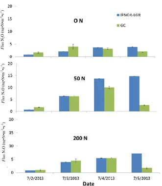
Fig. 10 shows the comparison between fluxes measured with the three manual chambers using the gas measurement methodologies: the GC, the IPNOA LGR spectrometer. For the GC, the lid of the chamber was deployed during 45 min and samples were taken every 15 min, for the LGR, it was only deployed during 4 min. For the GC measurements, mean ratio between slope and its standard deviation (∆b/b) was about 12% for 4 samples. For the GC measurements, the repeatability of the analysis leads to minimum flux detectable close to 1 ng·N·m-2·s-1. For the IPNOA-LGR measurements, its relative uncertainty was only 0.4%. Similar fluxes were observed between the two methods of gas analysis even if the chamber deployment durations were very different (45 min for GC analysis and 4 min for the IPNOA-LGR).
Surprisingly, fluxes for the 50 N treatment were higher than for the 200 N treatment. Nevertheless, measurements were carried out before the second irrigation July 8. Before this date, soilmoisture content was probably insufficient to discriminate N2O production according to the level of nitrogen treatment.
Fig. 10 Comparison between GC and LGR measurements using the frame of the three manual chambers. A lid was specifically adapted to fit the inlet and outlet of the two infra red spectrometers: LGR and QCL.
3.4 Tests with Calibration Gases: Sensitivity Response and Response Time of the Prototype
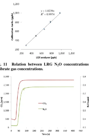
Fig. 11 shows the N2O concentrations obtained with LGR analyzer for the various calibrated gases. LRG response with the five calibration gases shows a good sensibility with a response of only 2% lower than certified gases. The 2% correspond to the gas concentration uncertainty given by the air liquid, the supplier of the calibrated gases.
Calibrated gas cylinders were used to estimate the response time (𝜏r) of the IPNOA prototype. Response time of the IPNOA prototype could be estimated with a sudden change of concentration in the inlet of the circuit.
Fig. 12 shows the variations of LGR concentrations just after connecting the input of the analyzer on a bag containing standard gas with a N2O concentration of 0.805 ± 0.016 ppm and CO2 of 2961.8 ± 8.9 ppm. The equilibrium concentration (Ceq) was reached for the
LGR after 100 s for CO2 (Ceq = 2,789 ppm) whereas
for N2O, it was reached after 200 s (Ceq = 778.6 ppb).
For N2O measurements, we can consider that 98% of
Flux N 2 O ( ng•N •m -2•s -1) Flux N 2 O ( ng•N •m -2•s -1) Flux N 2 O ( ng•N •m -2•s -1)
Cross-Validation of a Mobile N2O Flux Prototype (IPNOA) Using Micrometeorological and Chamber Methods
382
Fig. 11 Relation between LRG N2O concentrations and calibrate gas concentrations.
Fig. 12 Response IPNOA prototypes after connection with air-bag filled with calibrated gas.
balance is reached after 90 s, while for CO2, this value is reached 65 s after change of concentration.
The response time determines the lag-time to consider before starting calculation of the accumulation slope for flux estimation. This time was fond to be dependent mainly to the pump flow rate, the cell volumes of the LGR analyzers and length of inlet tubes. It depends only indirectly to chamber geometry (volume, area), to the extent that threshold of gas detection depend to the chamber V/A ratio.
The response time could be also estimated at first as the time necessary to purge the dead volume of the circuit considering (Fig. 2), the measurement circuit of the two analyzers in series used for the IPNOA mobile prototype. The CO2 analyzer (UGGA) is the first on the line and the N2O the second. The flow rate at atmospheric pressure (760 mm Hg) in the circuit is 250 cc·min-1. The length of the sample tubes is 20 m with an inner diameter of 2.5 mm ID (total volume about 113 cc). Cell volume for UGGA LRG was 315 cc and 401
cc for the N2O LGR. In the cells, pressure is limited to
90 mm Hg so the flow rate is then equal to 250 × 76090 cc·min-1. The response times are then equal to:
2 (113) (90 315) 36 s 250 250 760 CO
2 (113 16) (316 401) 90 52s 250 250 760 N O They are close to the values estimated in Fig. 12. To measure correctly the N2O emission, we must wait about 1 min 30 s (98% of the signal) before validating the start of accumulation phase of the N2O, for CO2 1 min is enough. The TD (time duration) for chamber deployment was evaluated to 4 min 90 s for the response time and 150 s was enough to evaluate the slope regression. This time allows optimizing the maximum of the slope with a weak perturbation of the gas transfer and to maximize the R2.
3.5 Test of Water Dilution
The N2O LGR also measures the water vapor concentration, so it was possible to test the effect of water dilution on N2O flux estimations. According to Rochette and Hutchinson [4], any increase in concentration of other gases resulting from chamber placement can affect N2O concentration. For example, Parkin and Ventura [8] demonstrate how an increase in water vapor concentration could decrease N2O concentration by 3%. This is known as the water vapor dilution effect and may cause an underestimation of N2O fluxes.
The raw N2O gas concentration is given in ppb unit corresponding to the ratio between partial pressure in N2O and total atmospheric pressure. The pressure in the LGR cell measured with barometric transducer depends also the partial pressure of water vapor (
P
H O2 ).We can write:
𝑁2𝑂 𝑟𝑎𝑤 =𝑃𝑃𝑁2𝑂
𝑇 (5)
N2O raw is the pressure fraction between the N2O gas ( PN O2 ) and total atmospheric gases (PT). To y = 1.0239x
R2
overcome the variation of the total atmospheric pressure during the chamber deployment time we must consider a dry concentration in N2O corresponding to the mixing ratio of the gas with a reference atmosphere without water vapor:
𝑁2𝑂 𝑑𝑟𝑦 = 𝑃𝑁2𝑂
𝑃𝑇−𝑃𝐻2𝑂 (6)
N2O dry could be also written as:
𝑁2𝑂 𝑑𝑟𝑦 = 𝑁2𝑂 𝑟𝑎𝑤
1− 𝐻2𝑂 𝑟𝑎𝑤 (7)
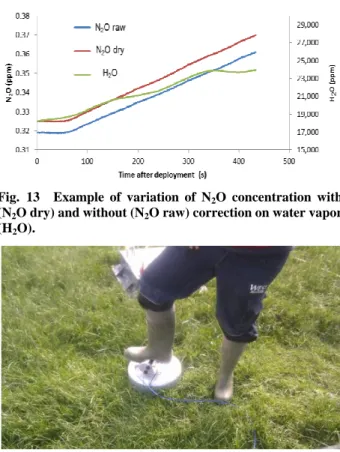
Fig. 13 shows an example of gas concentration accumulations after closing the chamber with and without correction on water vapor. N2O dry concentrations are about 7 ppb higher compare to the N2O raw concentrations. For a same measurement period, for this example, fluxes derived from the variations of the N2O dry signal were about 6.7% higher than those observed without correction for water vapor (N2O raw).
The effect of water vapor on N2O flux estimations will be largely dependent to the air humidity conditions and to the evaporation/condensation at the soil surface during chamber deployments. This effect is of the order of a few percent and should not be neglected.
3.5 Test of Sealing
To properly measuring the emission by enclosure chamber method, it is important to seal tightly chamber with the soil surface. Chamber systems are often composed of a collar and a lid. The collar is pressed into the soil at few cm few days before the measurement. The lid is then fixed to the collar air tightly. During the Easter Bush and Grignon experiments, the IPNOA chamber was maintain by foot pressure to the soil surface (Fig. 14).
But the seal was found insufficient. The alternative was to use collars pressed into the soil at few centimeter and positioned at different plot on the field, the chamber is now fitted at its base with a rubber with a groove, and is clipped to collars previously deployed in the field.
Fig. 13 Example of variation of N2O concentration with (N2O dry) and without (N2O raw) correction on water vapor (H2O).
Fig. 14 Technique initially used to compress the chamber to the soil surface.
3.6 Tests of Detection Limits
The detection limit in N2O emissions with IPNOA system was estimated when the deployments of the chamber were correct, without any air leak and when the emissions were weak. This detection limit depends on the LGR gas analyser noise level, the integrating time duration of the deployments, and the V/A ratios of the chamber. For the chamber „C‟ (V/A = 0.104 m) and for an integrating time of 150 s, according to the flux Eq. (4), the detection limit was around 0.03 ng·N·m-2·s-1. It is very nice score, with higher chamber like “B” chamber (V/A = 0.211 m), this threshold detection would have been two times higher.
The precision for ambient condition (i.e., N2O mixing ratio around 325 ppb) given by Los Gatos Research Inc. is 0.05 ppb for a measurement rate of 1 s. Applying the relation
t C A V Flux with a C = 0.05 ppb and t = 150 s, we obtain same value around 0.04 ng·N·m-2·s-1.
Cross-Validation of a Mobile N2O Flux Prototype (IPNOA) Using Micrometeorological and Chamber Methods
384
It should be noted that, the precision of 0.05 ppb is given only for the ambient concentration (325 ppb). For higher concentrations, the noise level will be largest and will conduce to greatest uncertainties for large N2O emissions.
The b term is inversely proportional to the root square of the measurement number. To minimize the uncertainty, it is important to establish an accumulation dynamic over more than 1 min period but after 3 min with a scan rate of 1 s, the gain on the flux accuracy is not so significant.
4. Conclusions
This cross validation demonstrated the proper functioning of the mobile IPNOA prototype according to various criteria that were tested:
Sensitivity: the responses of the prototype according to the entire range of emissions observable in the ecosystems of a grass land and an arable crops were very satisfactory given the comparisons with other devices (Eddy covariance, auto or manual chambers), and gas analyzers (Thermo 46C, GC, Aerodyne QCL) and gas standards that were deployed during the cross validation;
Short response time allowing limiting deployment time of the chamber. 90 s were enough to start gas accumulation phase. And 150 s to evaluate the rate of gas accumulation;
It is operational capacities in terms of mobility with stability in response of the gas analyzer and autonomy in electric power for less than 8 h;
The ease-of-use of the instrument: the remote transmission for the operation of the commands and acquisition of the data with a palm pilot was very use-friendly;
The weak limit of detection was also an important specificity. It is noteworthy, around 0.04 ng·N·m-2·s-1 and it is largely linked to characteristics of the LGR N2O analyzer. Five minutes of chamber deployment were enough to estimate fluxes with a high resolution;
The main problem observed during these
experiments was related to chamber sealing during their deployments. It was overcoming using collars pressed into the soil on which was clipped chamber during its deployment.
Acknowledgments
This research was carried out with the contribution of the LIFE financial instrument of the European Union, in the framework of the project LIFE+ IPNOA “Improved Flux Prototypes for N2O Emission from Agriculture” (2012-2016). A special thank is also due to the technical staff of INRA-EGC, Olivier Fanucci, Jean Christophe Gueudet and Celine Decuq. Thank to Daniela Famulari of CEH for her valuable help during the Easter Bush experiment.
References
[1] ISPRA (Instituto Superior per la Protezione e la Ricerca Ambientale). 2014. Italian Greenhouse Gas Inventory
1990-2012. National Inventory report 2014. Accessed
June 21, 2014. http://www.isprambiente.gov. it/it/pubblicazioni/rapporti/italian-greenhouse-gas-invento ry-1990-2012-national-inventory-report-2014.
[2] Weier, K. L., Doran, J. W., and Power, J. F. 1993. “Denitrification and the Dinitrogen/Nitrous Oxide Ratio as Affected by Soil Water, Available Carbon and Nitrate.” Soil Science Society of America Journal 57 (1): 66-72.
[3] Rochette, P., and Eriksen-Hamel, N. S. 2008. “Chamber Measurements of Soil Nitrous Oxide Flux: Are Absolute Values Reliable?” Soil Science Society of America Journal 5772 (2): 333-42.
[4] Rochette, P., and Hutchinson, G. L. 2005. “Measurement of Soil Respiration in Situ: Chamber Techniques.” In
Micrometeorology in Agricultural Systems, edited by
Hatfield, J., and Baker, J. M. Madison: American Society of Agronomy.
[5] Hensen, A., Groot, T. T., Bulk, W. C. M., Vermeulen, A. T., Olesen, J. E., Schelde, K. 2006. “Dairy Farm CH4 and
N2O Emissions, from One Square Meter to the Full Farm
Scale.” Agriculture, Ecosystems & Environment 112 (2-3): 146-52.
[6] Los Gas Research Inc. 2014. “Data Sheets of „Ultraportable Greenhouse Gas‟ and „N2O/CO (Nitrous
Oxide and Carbon Monoxide)‟ Analyzers.” Los Gas Research Inc. Accessed July 4, 2014. http://www.lgrinc.com/.
Cellier, P. P. 2011. “Effect of Management Climate and Soil Conditions on N2O and NO Emissions from an Arable
Crop Rotation Using High Temporal Resolution Measurements.” Agricultural and Forest Meteorology 151 (2): 228-40. doi:10.1016/j.agrformet.2010.10.008.
[8] Klein, C., and Harvey, M. 2012. Nitrous Oxide Chamber
Methodology Guidelines. Wellington: Ministry for
Primary Industries. Accessed December 9, 2012. http:// www.globalresearchalliance.org/research/livestock/activit ies/nitrous-oxide-chamber-methodology-guidelines/.
