Middlesex University Research Repository
An open access repository of
Middlesex University research
http://eprints.mdx.ac.uk
Cacciagrano, Diletta Romana, Corradini, Flavio, Culmone, Rosario, Gorogiannis, Nikos ORCID:
https://orcid.org/0000-0001-8660-6609, Mostarda, Leonardo, Raimondi, Franco and Vannucchi,
Claudia (2018) Analysis and verification of ECA rules in intelligent environments. Journal of
Ambient Intelligence and Smart Environments, 10 (3). pp. 261-273. ISSN 1876-1364
(doi:10.3233/ais-180487)
Final accepted version (with author’s formatting)
This version is available at:
http://eprints.mdx.ac.uk/24501/
Copyright:
Middlesex University Research Repository makes the University’s research available electronically.
Copyright and moral rights to this work are retained by the author and/or other copyright owners
unless otherwise stated. The work is supplied on the understanding that any use for commercial gain
is strictly forbidden. A copy may be downloaded for personal, non-commercial, research or study
without prior permission and without charge.
Works, including theses and research projects, may not be reproduced in any format or medium, or
extensive quotations taken from them, or their content changed in any way, without first obtaining
permission in writing from the copyright holder(s). They may not be sold or exploited commercially in
any format or medium without the prior written permission of the copyright holder(s).
Full bibliographic details must be given when referring to, or quoting from full items including the
author’s name, the title of the work, publication details where relevant (place, publisher, date),
pag-ination, and for theses or dissertations the awarding institution, the degree type awarded, and the
date of the award.
If you believe that any material held in the repository infringes copyright law, please contact the
Repository Team at Middlesex University via the following email address:
[email protected]
Analysis and verification of ECA rules in
Intelligent Environments
Diletta Romana Cacciagrano, Flavio Corradini, Rosario Culmone,
Nikos Gorogiannis, Leonardo Mostarda, Franco Raimondi, Claudia Vannucchi
Abstract
Intelligent Environments (IEs) are physical spaces where Information Tech-nology (IT) and other pervasive computing technologies are combined in order to achieve specific goals for the users and the environment. IEs have the goal of en-riching user experience, increasing awareness of the environment. A number of applications are currently being deployed in domains ranging from smart homes to e-health and autonomous vehicles. Quite often IE support human activities, thus essential requirements to be ensured are correctness, reliability, safety and secu-rity. In this paper we present how a set of techniques and tools that have been developed for the verification of software can be employed in the verification of IE described by means of event-condition-action rules. More precisely, we reduce the problem of verifying key properties of these rules to satisfiability and termination problems that can be addressed using state-of-the-art Satisfiability Modulo Theory (SMT) solvers and program analysers. Our approach has been implemented in a tool called vIRONy. Our approach has been validated on a number of case studies from the literature.
1
Introduction
IE are physical environments that combine together information, sensor and commu-nication technologies into everyday physical objects, infrastructures, and the surround-ings we live in. IE enhance everyday activities and allow new applications that were not possible before. IE applications and scenarios include smart homes, e-healthcare, e-learning, smart factories and autonomous vehicles [1]. IE are a type of reactive sys-tems[2] which maintain a continuous interaction with the environment by reacting to any stimulus (or event) that occurs in it.
The paradigm Event-Condition-Action (ECA) [3, 4] is a widely used approach to program reactive systems. An ECA program contains rules of the form: if a certain eventhappens and a condition is met, then a specific action is executed. IE have a great impact on daily life, thus it is essential for IE to meet requirements of correctness, reliability, safety, security and desired reliable behaviour [5]. These properties are quite hard to be ensured since programming rule-based systems is a difficult and error-prone process [6, 7]. More precisely, the interactions of rule actions can cause the
system behaviour to be unpredictable or unsafe, thus verification of consistency and safety properties of IE systems has became a necessity [8].
Various approaches have been proposed in order to ensure IE properties. For in-stance, software testing [9] has been widely used to improve software quality. While testing can provide correctness of different systems, it is not adequate for IE where an adequate notion of coverage is missing and the environment in which the system runs is unpredictable. Formal methods techniques can provide an effective solution for analysing and establishing the correctness of IE systems, especially for applications where safety is a critical issue. One of the formal approaches closer to ours is pre-sented in [10]. It proposes a method to analyse the dynamic behaviour of a set of ECA rules by first translating them into an extended Petri Net [11]. This allows the checking of termination and confluence properties. Authors in [12] investigate the possibility of using a pure Binary Decision Diagram ([13]) representation of integer values, and they focus on a particular class of programs. These are ECA rule-based programs with restricted numerical operations. In [14] a tool-supported method for verifying and controlling the correct interactions of ECA rules is presented. This method generates correct rule-based controllers and is based on formal models that are related to reactive systems. The authors in [15] propose a formalisation of an ECA rule-based system that is translated into a Heptagon/BZR program. This offers to the users a combination of a high-level ECA rule language with a compiler and a formal tool support for Hep-tagon/BZR. In [16], a set of ECA rules is transformed into different kinds of automata and then the automata verification tool Uppaal [17] is applied. The approach is lim-ited to performing model checking of timed automata and their correspondence to the provided ECA rule set.
1.1
Our contribution
In this paper we present a novel theoretical framework for the verification of ECA rules in intelligent environments. Our framwork is based on software verification techniques and is implemented in the vIRONy tool1. vIRONy is based on the combination of formal methods and simulation techniques, with the aim of supporting programmers and end-users during the modelling and verification phases of IE systems that are based on ECA-rules. The features of vIRONy include:
• a syntactic analyser for checking the correctness of the source program and for enabling users to identify and avoid syntactic errors;
• a formal verification component based on different techniques (SMT solvers and program analysers) to check safety and correctness of the program expressed as a set of ECA rules;
• a simulation environment to generate and investigate specific behaviours of the system;
1The current version of vIRONy is open source and it is available at https://gitlab.com/
1 Program ≡ ( Device | Rule | VarDecl )+;
2 Device ≡ PhysicalDevice | LogicalDevice | Set;
3 PhysicalDevice ≡ physical (sensor|actuator)
4 Type Id [= Exp]
5 node(Id Sep Id)[in id (Sep Id )*][where BoolExp];
6 LogicalDevice ≡ logical (sensor|actuator)
7 Type Id = Exp[in Id (Sep Id )*] [where BoolExp];
8 Set ≡ set (sensor | actuator) Type Id;
9 Rule ≡ rule Id on Id (Sep Id)*when BoolExp then Action;
10 Action ≡ [Id = Exp ]+;
11 Exp ≡ BoolExp | IntExp;
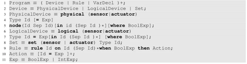
Figure 1: The IRON extended BNF
• a semantic analyser used to perform qualitative and quantitative analysis of the system in terms of number of rules invoked, energy efficiency, etc.
Compared to our approach, the ones in [10] and [12] do not provide methods for verifying application-specific properties like redundancy, consistency and usability of rules. The work presented in [16] is not tailored to a specific rule language and requires a specific model checking tool, while the verification methods proposed in our work are based on a domain-specific language for IE, and allow the definition and the im-plementation of verification algorithms that can use efficient techniques such as SMT solvers and theorem provers. These can enable the verification of application-specific properties. With respect to our approach, in [14] properties such as correctness and us-ability are not considered for verification. Redundant rules are not directly detected by Heptagon/BZR [15]. Duplicated rules are compiled and executed at run-time and rule actions are activated using the or operator. Instead, our approach enables end-users to identify redundant rules and decide how to modify the program; therefore it allows a deeper analysis and understanding in the design phase, giving to the programmer a greater control on the system he or she intends to develop.
2
Preliminaries and notation
In this section we recall IRON [18], a domain-specific language for IE based on ECA rules and the formal model expressing its semantics [19].
IRON (Integrated Rule ON data) is a restricted first-order logic language that sup-ports the categorisation of devices into sets [20], allows the definition of properties over sets and supports multicast and broadcast abstractions. We report the main constructs of the IRON syntax in Fig. 1 [21].
The formal model for the execution of ECA rules in IRON exploits the features that are typical of IE, taking into account the fact that a generic action defined by the user can only change actuator configurations. For the sake of simplicity but without loss of generality, the formal model does not include the definition of sets and the distinction between logical and physical devices included in IRON (these could be introduced at the cost of additional notation but do not affect the overall partitioning strategy described below).
This uses the function ψai,aj of Figure 7 which returns true when two different
actions aiand ajmodify the actuators in the same ways (i.e., no contradiction occurs).
We consider an ECA-rule based system consisting of: (i) a set D of variables rep-resenting the input/output devices of the system, denoted with i and o respectively (to refer to a generic element of D we use the letter d); (ii) a set Inv of static constraints invof the system identifying the admissible values for each device (each invariant is a restricted first-order logic predicate as defined by the IRON grammar); (iii) a set R of ECA rules of the form Event[Condition]/Action.
A state of the system is an assignment of values to the devices in D and the universe is the set of states. In detail:
Definition 1. A state of the system is a function ϕ : D → Val where Val is a finite set of integer or boolean values.
Definition 2. The universe Φ of an ECA-rule based system is the set of all possible states of the system, i.e., the set of all possible functions ϕ in definition 1.
By adding constraints to the system, i.e. conditions that must be satisfied, we can define the admissible state space:
Definition 3. Let Φ be the universe. The admissible state space Φais the subset of Φ
whose elements are all the states ϕ that satisfy the constraints of the system.
Given D and Φ , we consider a finite set R of labels for ECA rules R = {r1, r2, ..., rk}
for k ∈ N0. A generic rule r in R is represented as er[cr]/ar, where er, cr, arare labels
for the event, the condition and the action of r respectively.
We observe that devices can change their values according to external changes (sensors) or internal changes (actuators change their values in response to ECA rules being triggered). As a consequence, the evolution of the system can be partitioned into two sets: the set of artificial transitions resulting from the activation of ECA rules, and the set of natural transitions that result from changes in the environment. According to this partitioning, we can distinguish between stable and unstable states: the system is in a stable state if only natural transitions can be applied, while unstable states are those states to which only artificial transitions can be applied.
Figure 2: System behaviour
We use the generic example represented in Fig. 2 for a clarification of how natural transition (denoted by tNand dotted arrows) and artificial transition (denoted by tAand
solid arrows) interact. In this figure, white circles are unstable states in Φa, while
green states are stable states. States are grouped together into three sets, A1, A2, A3in
sets. Inside each set, the states are linked to each other via artificial transitions, since changes are due only to actuator values.
The representation of the evolution of the system is based on two important hy-potheses: (1) the initial admissible configuration of the system is given by an external entity; (2) artificial transitions take much shorter time than natural transitions.
Finally, since we consider a finite set of devices that can assume a finite set of values, it is possible to represent the evolution as a Finite State Automaton (FSA) [22], where the edges correspond to the transitions of the system and the vertices to its states.
3
Properties and verification algorithms
Our aim is to avoid “unsafe” and “incorrect” situations deriving from erroneous defi-nitions of ECA rules that may result in inefficient or potentially dangerous effects on the real world. Based on literature review of related and previous works [18, 14], we identify the following properties that can be considered representative for “safety” and “correctness” of ECA rule-based systems: termination, consistency and determinism. We formally define each of them and we present the verification algorithms below.
3.1
Termination
Definition 4. An ECA rule-based system satisfies the termination property when all stable states (that satisfy the conditions of some rules) always lead (with the application of a finite number of rules) to a new stable state.
In order to prove termination we make use of T22(see [23, 24, 25]), a tool designed to prove temporal properties of programs, such as safety and termination. The tool implements the TERMINATOR-based approach to termination proving (see [26]) with some modifications. The idea of the technique is to reduce the checking of termination arguments to an incrementally evolving safety problem. T2 represents programs as graphs of program locations connected by transition rules with conditions (expressed by the command “assume”) and assignments to a set of integer variables V . The canonical initial location is called START.
Given a generic rule-based program written in IRON syntax, we show the encoding into T2 format in Fig. 3. Consider a generic program in IRON consisting of a set of devices D, a set of rules R and a set of invariants Inv set (see lines 1 − 3 in Fig. 3). We consider the set of initial states characterised by an assigned configuration of actuator values (line 4). We define a set of variables in lines 5 − 13 that are used for the translation. Lines 14 − 40 describe the algorithm for generating the program in T2 format. This program corresponds to the automaton represented in Fig. 4 that is characterised by two states that we generically name 0 and 1. The execution starts from state 1, characterised by the assigned configuration of values, a generic configuration of sensors (the function nondet() assigns values randomly). In addition, state 0 is admissible, as the invariants are assumed as valid (line 17). A natural transition (line 26) corresponds to a transition from state 0 to state 1. When a natural transition moves
1 letD= I ∪ Othe set of declared labels
2 letR:= {r1,....,rk}the set of rules such that eachr∈ Ris of the formr: er [cr ]arwhereer = {dw1 ,··· ,dw f } ⊂ Dand
ar = {oα1 ← vα1 ,···oαp ← vαp },withoα1 ,... ,oαp ∈ O 3 letInv set:= {inv1,....,invv}
4 leto= valthe initial value foro∈ O
5 defineInv= v ^ j=1 inv j 6 for eachd∈ D: 7 defined_changed 8 for eachr∈ R
9 for eachoα j ∈ ar
10 defineo_prime 11 for eachd∈ er
12 letd_check= (d_changed!= 0)
13 defineeT2_r= _ d∈er d_check 14 write 15 START: 0; 16 FROM: 0;
17 assume(Inv); //invariants
18 for eachi∈ I //sensor initial values 19 writei:=nondet();
20 for eacho∈ O //actuator initial values 21 writeo:=val;
22 for eacho_changed//actuators changes 23 writeo_changed:= 0;
24 for eachi_changed//sensors changes 25 writei_changed:=nondet();
26 TO: 1;
27 for eachr∈ R
28 write//rule r 29 FROM: 1;
30 assume((Inv) && (eT2_r) && (c_r));
31 for eachoα j ∈ ar
32 write
33 o_prime:=vα j ;
34 o_changed:= (o-o_prime);
35 o:=o_prime;
36 for eacho∈ Osuch thato6= oα j ∈ ar∀ j
37 writeo_changed:= 0;
38 for eachi∈ I
39 writei_changed:= 0;
40 TO: 1;
41 end
Figure 4: Execution model of IRON programs in T2.
the state from 0 to 1, the rules in R, i.e., the artificial transitions of the system, as shown in Fig. 4, can be applied when their corresponding event is met (line 30).
Proposition 1. The algorithm in Fig. 3 is correct.
Proof. First, we show that if a generic ECA rule can be activated in an IRON program (PIRON), then it can be activated in the corresponding T2 program (PT2) too, and
vice-versa. Indeed, given a generic PIRON and a generic ECA rule r : er[cr]ar such that
r∈ PIRON, the rule is activated if and only if: (i) the invariants are valid; (ii) the event
er is triggered (i.e., if a change concerning the value of at least one of the labels in er
occurs); (iii) the condition cris valid. As shown in Fig. 3, these three conditions are all
reported verbatim in the assume at line 30. Now we show that there is an equivalence in the execution semantics of PIRONand PT2programs. If a natural change occurs, then
ECA rules whose events capture this natural evolution are considered for an eventual activation. The natural transitions correspond in PT2 to the transition FROM 0;[..]
TO 1;(line 16 − 26), and the natural changes correspond to the assignments to sensor variables through the nondet() function (line 19). When a natural evolution occurs, and the program PT2is in state 1 then, if conditions (i)-(iii) are met for a certain ECA
rule, this rule is executed. Furthermore, the activation of the ECA rules in PIRON is
non-deterministic, and this non-determinism is maintained in PT2, since all rules are
applied to the state 1 (FROM 1 at line 29). When an activation of an ECA rule in PIRON
is performed, the system is frozen, in the sense that natural transitions are not taken into account: this condition in PT2is fixed at lines 38 − 39. The T2 program does not
allow any other kind of transition between states, and therefore the executions of the IRON and the T2 program are isomorphic.
3.2
Consistency
Definition 5. An ECA rule-based system satisfies the consistency property if its rules are neither unusable nor incorrect nor redundant.
The notions of unused, incorrect and redundant rule are defined as follows. Definition 6. An ECA rule r ∈ R is called unused if the condition c is false for every state ϕ ∈ Φa.
Since the set Φais the set of all states in Φ satisfying all the invariants of the system,
we can alternatively say that r is unusable if the logical predicate
P= c ∧ inv1∧ inv2∧ · · · ∧ invv (1)
Definition 7. Incorrect rules are those rules that can lead to a state that is outside of Φa.
Definition 8. Given ri, rj∈ R such that ri: ei[ci]/ai, rj: ej[cj]/aj we say that ri is
redundant with respect to rjif the following conditions are met:
1. ei⊆ ej;
2. ci∧ Inv ⇒ cj is satisfiable (where, by slight abuse of notation, we denote with
Inv the conjunction of all invariants); and,
3. for every state ϕ satisfying ci∧ Inv, applying aito ϕ is equivalent to applying aj
to ϕ, which we write as ϕ[ai] = ϕ[aj].
The algorithms for verifying the consistency property are described in detail in [21]. The key insight of the verification approach is observing that it is possible to perform consistency verification of ECA rule-based systems by using Satisfiability Modulo Theories (SMT) [27, 28] and predicate transformer techniques ([29, 30]). We briefly report in this paper the verification algorithms.
An SMT solver is any software that implements a procedure for satisfiability mod-ulosome given theory, for example the theory of linear arithmetic. Typically, SMT solvers support several fragments of First Order Logic (FOL). The solution of an SMT problem is an interpretation for the variables, functions and predicate symbols that make the formula true [28]. We use Z3 [31], a high-performance SMT Solver imple-mented in C++ and developed by Microsoft Research.
The detection of unused rules is based on definition 6. Given a generic rule r : e[c]/a, we have to check whether the rule can be triggered and whether the condition cis satisfiable in Φa. This is equivalent to asking a (sound and complete) SMT solver
whether there exists ϕ such that formula P defined in (1) is satisfiable. If P is satisfiable, the rule r can be used, otherwise it is unusable. The algorithm is reported in Fig. 5.
1 letR:= {r1,....,rk} 2 letI:= {inv1,....,invv} 3 defineInv= v ^ j=1inv j 4 for eachi= 1, ..., k:
5 if(ci ∧ Inv)isunsatisfiable:
6 declareri unused
7 end
Figure 5: Algorithm for detecting unused rules.
In order to verify the correctness of the generic rule r : e[c]/a according to definition 7, we compute the weakest precondition PInvfor the set of invariants, i.e., the formula
PInv= wp(a, Inv) . In order to declare the rule r correct, the set of states where the
rule may apply must be contained into the set of states PInv, otherwise there would
exist a state where the rule applies, but from which we can reach a state outside those satisfying the invariants. Therefore, we translate this problem into the following SMT instance: (c ∧ Inv) ∧ ¬PInvand we verify that this is not satisfiable. If the solver answers
1 letR:= {r1,....,rk} 2 letI:= {inv1,....,invv} 3 defineInv= v ^ j=1inv j 4 for eachi= 1, ..., k:
5 if(ci ∧ Inv) ∧ ¬wp(a,Inv)issatisfiable:
6 declareri incorrect
7 end
Figure 6: Algorithm for incorrectness verification.
that the proposition is satisfiable, then we conclude that the rule r is incorrect, otherwise we declare that r is correct. The algorithm is described in Fig. 6.
The detection of redundant rules is performed under the following hypothesis on the ECA rule structure: we will consider only rules r : e[c]/a where a is a non-empty set of linear functions over integer variables in D. In order to detect redundant rules, we have to check whether conditions 1-3 of definition 8 are verified. The algorithm is described in Fig. 8. ψai,aj(o) = > if o ↑ aiand o ↑ aj o= Ej if o ↑ aiand (o ← Ej) ∈ aj Ei= o if (o ← Ei) ∈ aiand o ↑ aj Ei= Ej if (o ← Ei) ∈ aiand (o ← Ej) ∈ aj Ψ(ai, aj) = ^ o∈O ψai,aj(o)
Figure 7: Preliminary definition.
1 letR:= {r1,....,rk} 2 letI:= {inv1,....,invv} 3 defineInv= v ^ j=1 inv j
4 for eachordered pair(ri,r j ) ∈ R2such thatri 6= r j and
5 such thatri,r jareusable:
6 if(ei ⊆ e j ) and (not(ci ∧ Inv ⇒ c j )isunsatisfiable) and
7 not(ci ∧ Inv ⇒ Ψ(ai,a j ))isunsatisfiable):
8 declareri redundantwith respect tor j
9 end
Figure 8: Algorithm for redundancy verification.
3.3
Determinism
Definition 9. Given ri, rj∈ R such that ri: ei[ci]/ai, rj : ej[cj]/aj, we say that the
system is non-deterministic if the following conditions are met: 1. ei∩ ej6= /0;
2. ci∧ Inv ∧ cjis satisfiable;
3. ∃ ϕ that satisfies ci∧ Inv ∧ cjand ϕ[ai] 6= ϕ[aj].
A pair of rules ri, rj is non-deterministic if there is at least one admissible state in
which both rules are triggered and the effects of their actions on the system are not the same. Condition 1 means eiand ejhave at least a common label. Thus this condition,
if met, guarantees that at least the occurrence of an event triggers both riand rj. If both
1. and 2. are verified, then ri and rj are applicable to the same state. If the result of
applying action aiis different from the result of applying ajfor at least one state ϕ in
ci∧ Inv ∧ cj, then riand rjmake the system non-deterministic.
The verification procedure of the determinism property is very similar to that one of redundancy, and it is performed under the same hypothesis. The algorithm is described in Fig. 9. All the pairs of distinct rules are considered. According to definition 9, three conditions must be verified: if two rules are triggered together, i.e., the event parts have a least a common label, both conditions are met, and the actions have different effects on the system, then the system is non-deterministic. The procedure described below must be performed for all pairs of rules (line 4) .
1 letR:= {r1,....,rk} 2 letI:= {inv1,....,invv} 3 defineInv= v ^ j=1 inv j
4 for eachpairri,r j ∈ R2such thatri 6= r j andsuch thatri,r jareusable:
5 if(ei ∩ e j )is non-emptyand((ci ∧ Inv ∧ c j )issatisfiable)
6 and¬(ci ∧ Inv ⇒ Ψ(ai,a j ))issatisfiable):
7 declarethe systemnondeterministic
8 end
Figure 9: Algorithm for verifying determinism.
Proposition 2. The algorithm in Fig. 9 is correct.
Proof. The proof is similar to that one of the correctness of the algorithm for the ver-ification of redundancy (see [21] for further details). Indeed, requirements (1) and (2) of definition 9 are checked verbatim in the algorithm. Thus, it remains to show that the algorithm is correct w.r.t. requirement (3). It can be rewritten as follows: ∃ϕ 6|= ci∧ Inv ∧ cj, ϕ[ai] = ϕ[aj] . Notice that requirement (3) of definition 9 is
equiva-lent to the negation of requirement (3) of definition 8.
4
The tool vIRONy
In this section we give a quick overview of vIRONy, the prototype tool that has been implemented to evaluate the proposed approach.
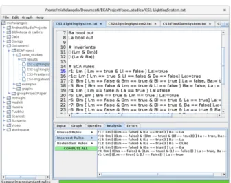
- Graphical User Interface (GUI): Fig. 10 depicts the GUI of the tool: users can select input files written in IRON syntax and select the desired functionality.
When the user opens a file for the first time, a TabbedPane is opened. The main components of the TabbedPane are:
Figure 10: Graphical User Interface of vIRONy
• Development area: it is a TextArea the user can use to write or modify the pro-gram.
• Functionality panel: the user can access the desired functions in order to analyse or generate a simulation of the program.
In detail, by accessing the Functionality panel the user can insert the initial configura-tion of values (Input tab), visualise the resulting graph of the simulaconfigura-tion generated by using the GraphStream library (Graph tab), make queries on the resulting simulation (Queries tab), perform a formal analysis of the program (Analysis tab), check if the output console gives errors (Errors tab). At the bottom, a Progress Bar indicates which operation is currently performed.
- Syntactic analysis The parser of vIRONy is implemented using Java Compiler Com-piler3. The vIRONy parser only accepts input files written in IRON. As we showed in
Section 2, the IRON language consists of two main components, the static part which includes labels and invariants, and the dynamic part that is made up of ECA rules. La-bels are used to uniquely identify the devices of the system. Each label declaration must contain the name of the device, the value type (int or bool) and the device cat-egory (in or out). The declaration of the invariants consists in a boolean expression enclosed by square brackets. The syntax of ECA rules is rule : event[condition]action, where rule is a string that uniquely identifies a rule, the event is a non-empty set of labels (guards) separated by commas, the condition is a boolean expression, the action is a set of assignments to actuators. It is only possible to specify a non-empty set of assignments to be executed simultaneously; as a consequence an actuator label can be written in at most one left hand side of an assignments. This property is controlled through a semantic check. In addition, the labels in the event and action parts must
have been declared in the declarative part of the program and the the expression on the right side of each assignment must be of the same type of the actuator on the left side.
The user can write the input file using the TextArea or visualise an existing one and, before performing any kind of operation (e.g. simulation, formal analysis, etc.), the parser is automatically called in order to check the syntactic correctness of the program. If there are errors, the chosen operation is cancelled and it is possible to visualise the errors found through the Errors tab that is automatically opened by the tool.
- Formal verification: The verification procedure is based on the formal techniques described in Section 3. Given an input file, the user can access the formal verification by using the Analysis tab. For each property a specific tab is provided to the user to perform specific analysis. Furthermore, an additional button Consistency allow the verification of correctness, non-redundancy and usability, and the user can visualise the results in a specific area.
Termination verification:vIRONy provides the users with a procedure for translat-ing the input file written in IRON syntax into the T2 format. The file is then stored in the computer, and available as input file for T2. T2 is run from the command line, using the termination: command line argument (to prove (non)termination). The user can select the initial configuration of values for the actuators, and then by submitting them, verification of termination is performed.
Consistency and determinism verification:The verification of consistency and de-terminism properties implemented in vIRONy makes use of the SMT solver Z3. From an implementation perspective, in order to use Z3, a recursive algorithm has been im-plemented to translate the expressions generated by the parser into expressions seman-tically equivalent to the initial ones that can be verified using the SMT solver. Ac-cording to definition 5, in order to verify if a given ECA-rule based system written in IRON syntax is consistent, we have to check whether its rules are neither incorrect nor unusable nor redundant.
Determinism: for what concerns the verification of the determinism property, the tool implements the algorithm presented in Section 3.
- Simulation: we provide users and programmers with a function to simulate a possi-ble behaviour of the system given a particular configuration of actuators. The simula-tion generated by vIRONy is based on the formal model introduced in Secsimula-tion 2 and explored in detail in [19]. Before explaining the simulation procedure, we make a pre-liminary observation: for the sake of simulation and differently from the verification step using Z3 and T2, devices can assume only a finite set of values (we choose for integers the range [−128, 127], but this arbitrary choice can be easily changed).
From the user perspective, the Simulation menu allows to start a computation. Af-ter having pressed the button Start simulation the Input tab at the bottom is configured to allow the user to set the initial configuration of values. Then Z3 checks if it is admissible for the system: if the configuration is admissible, the simulator starts the procedure, otherwise an alert is generated for the user. If the user only gives the con-figuration of the actuators, the system automatically searches for the concon-figuration of sensors such that the complete state is admissible (by default the system searches for
the “minimum” sensor configuration according to the lexicographic order of the ele-ments of the table containing only sensor labels). Once a configuration is found, the simulator starts the generation procedure of the transitions (for performance reasons, unused rules are not taken into account). The tool automatically visualises the resulting graph in the corresponding tab for further analysis. It is possible to export the graph in the GraphML format4or as an image by selecting the desired option from the Graph menu.
We provide different strategies for a deeper understanding of the rules applied dur-ing the simulation from a quantitative perspective that is strictly linked to energy savdur-ing problems. Different algorithms have been implemented and they have been grouped to-gether under the Queries tab. We highlight the fact that the analysis is based only on the graph resulting from the simulation, so the results depend on the initial configuration chosen by the user. We mention here a subset of the algorithms available:
• Rules count. This indicator counts how many times each rule is triggered during the simulation. When the simulation presents a cycle, the number assigned to those rules associated to the cycle is infinite (this would also implies that the system is non-terminating).
• Most used rules. This query is used to find out the rules that are used the maxi-mum number of times during the simulation.
• Initial rules. This query asks the simulation for those rules that are triggered by a natural event.
• Actuator updates. This measure counts how many times the values of the actua-tors are modified by ECA rules.
• Find cycles. The query extracts the cycles from the graph and reports the graph-ical representation of each cycle.
• Find paths. This query explores the graph and finds out all possible paths reach-ing a certain state of the system startreach-ing from another one.
5
Evaluation
In this section we consider four case studies taken from related and previous work and we present performance results. We report only results and we refer to the files available on-line for further details. All the experiments have been performed on an Intel Core i7-4700MQ CPU @ 3.4GHz with 8GB of RAM running Debian Linux.
The first case study (CS1) is a lighting control system in a simple scenario and it has been adapted from the example presented in [21]. The input file for vIRONy is shown in Figure 11. For what concerns the consistency property, the verification procedure declares r5 as unusable, rules r1, r9, r10, r11, r12, r13, r14 as potentially incorrect (for instance, rule r1 doesn’t identify any condition on Ba, while r1c is a possible correct version of r1), rules r4, r6, r7, r8, r19 do not satisfy the non-redundancy property. In
addition, the system is declared non deterministic. For what concerns the termination verification, the result is “Termination/nontermination proof failed”, meaning that the tool T2 cannot find a proof strategy in this case. This means that developers may need to provide manual evidence of termination properties. In this simple scenario the house is composed of two rooms: the living room (L) and the bedroom (B). The entrance is in the living room and the bedroom is accessible from the living room. Both rooms contain a motion sensor (m), a light sensor (l), a light switch (s) to turn on and off the light manually, a light actuator (a) to automatically turn on and off the lamp.
We assume that only one person has access to the house at any given time. In Figure 11 the invariants of the system are declared at lines 2 − 3. The first constraint states that the person cannot stay in both rooms simultaneously. The second one states that light actuators cannot be both on at the same time. As a consequence, according to the first constraint, a state having both light actuators on is not admissible. At the end of the verification procedure, among the rules reported in Fig. 11, the rule r5 is declared unused, since the condition is never met, r1 is incorrect, since it could lead outside of the domain if applied to a state having Ba := true (a possible correct version of r1 is r1c). Rules r11 and r13 are incorrect, since they lead the system to an non-admissible state. Among usable and correct rules, the verification procedure declares rule r7 redundant with respect to r2, rules r4 and r19 are mutually redundant, rule r6 is redundant with respect to r2, r7, r8, while rule r8 is redundant with respect to r2, r6, r7. The second case study (CS2) has been adapted from [10], where a light control subsystem in a smart home for senior housing is considered. The number of devices is greater than that of CS1, and also the overall dynamic of the system is more com-plex. Indeed, by using motion and pressure sensors (Mtn, Sl p respectively), the system attempts to reduce energy consumption by turning off the lights in unoccupied rooms or if the occupant is asleep, and it also provides automatic adjustment for indoor light intensity based on an outdoor light sensor (ExtLgt). We made some changes in the admissible values for lgtsT mr and in the rules involving this variable. Indeed, our tool automatically fixes upper and lower bounds (we choose the values of +127, −128 respectively) for those integer variables that have no limited values. We also defined some additional rules with respect to the original version of the case study in order to have a greater number of rules to be analysed. We report in Figure 12 a subset of input file for vIRONy. The formal analysis declares r14 as unusable, rule r2 as potentially incorrect (since there is no upper bound for lgtsT mr, but for instance rule r2c is a pos-sible correct version of r2), rule r11 is redundant with respect to r5. In addition, the system is declared non-deterministic. In this case, T2 can find a proof of termination and it gives the result “Termination proof succeeded”. Notice that by relaxing our addi-tional constraints on variable bounds and by removing the addiaddi-tional rules the scenario would be non-terminating.
The third case study (CS3) has been developed starting from the example presented in [32] and described in [21]: a fire alarm system composed of temperature sensors, smoke detectors and sprinkler actuators is described by means of ECA rules. When a temperature sensor reads a value that exceeds a specified threshold and a smoke sensor detects smoke all the sprinklers are activated. Among the rules defined in Figure 13, rules r7, r8, r11 are declared unused, there are no incorrect rules and for what concerns redundancy, r9 is redundant with respect to r1 and r10 is redundant with respect to r2.
1 #Declaration 2 Bl bool in 3 Bm bool in 4 Bs bool in 5 Ll bool in 6 Lm bool in 7 Ls bool in 8 Ba bool out 9 La bool out 10 11 #Invariants 12 [!(Lm&Bm)] 13 [!(La&Ba)] 14 15 #ECA rules
16 r1:Lm[Lm==true&Ll==false]La:=true
17 r1c:Lm[Lm==true&Ll==false&Ba==false]La:=true
18 r2:Bm[Lm==false&Bm==true&Bl==true]La:=false,Ba:=true 19 r3:Bm[Bm==false&Lm==true&Ll==false]Ba:=false,La:=true 20 r4:Lm[Lm==false&La==true]La:=false
21 r5:Lm,Bm[Bm==true&Lm==true]La:=true
22 r6:Bm[Lm==false&Bm==true&Bl==true&La==true]La:=false,Ba:=true 23 r7:Bm[Lm==false&Bm==true&Bl==true&Ba==false]La:=false,Ba:=true
24 r8:Bm[Lm==false&Bm==true&Bl==true&La==true&Ba==false]La:=false,Ba:=true 25 r9:Bm[Bm==false&Lm==true&Ll==false]Ba:=true,La:=true
26 r10:Bm[Lm==false&Bm==true&Bl==true]La:=true,Ba:=true 27 r11:Lm[Lm==false&La==true]Ba:=La
28 r12:Lm[Lm==false&La==true]Ba:= !Lm 29 r13:Lm[Lm==false&La==true]Ba:=La 30 r14:Lm[Lm==false&Ba==true]La:=Ba
31 r15:Ba[Ba==true&La==false]Ba:=false,La:=true 32 r16:La[Ba==false&La==true]Ba:=true,La:=false
33 r17:Bm[Lm==false&Bm==true&Bl==true]La:=false,Ba:=false 34 r18:Bm[Bm==false&Lm==true&Ll==false]Ba:=false,La:=false 35 r19:Lm[Lm==false&La==true]La:=false
Figure 11: CS1: IRON program for the lighting control system in a simple scenario.
1 #Invariants
2 [ExtLgt>= 0 &ExtLgt<= 10 ]
3 [lgtsTmr>= 0 &lgtsTmr<= 120 ]
4 #ECA rules
5 r2:Mtn,ExtLgt,Slp[lgtsTmr>= 1 &Mtn==false]lgtsTmr:=lgtsTmr+1
6 r2c:Mtn,ExtLgt,Slp[lgtsTmr>= 1 &Mtn==false&lgtsTmr< 120 ]lgtsTmr:=lgtsTmr+1
7 r5:ChkExtLgt[ChkExtLgt==true&Lgts==false&ExtLgt<= 5]Lgts:=true 8 r11:ChkExtLgt[ChkExtLgt==true&Lgts==false&ExtLgt<= 4]Lgts:=true
1 #Invariants
2 [temperature> -80 &temperature< 60]
3 #ECA rules
4 r1:temperature[temperature< 16 ]heating:=true 5 r2:temperature[temperature> 18 ]heating:=false
6 r7:temperature[temperature< 30 &temperature> 30 ]tempAlarm:=true 7 r8:temperature[temperature>= 1000 ]tempAlarm:=true
8 r9:temperature[temperature== 14 ]heating:=true 9 r10:temperature[temperature> 20 ]heating:=false
10 r11:temperature[temperature< 15 &temperature> 50 ]tempAlarm:=true
Figure 13: (CS3) ECA rules for a fire alarm system.
1 #Invariants 2 [ (!f|w) ] 3 [ !(r&w) ] 4 [c>= 0 &c< 120 ] 5 [t>= 0 &t< 120 ] 6 #ECA rules
7 r2:t,w[t-c> 2 &w==true]w:=false,c:=t
8 r2c:t,w[t-c> 2 &w==true&f==false]w:=false,c:=t 9 r4:t,w[t-c> 2 &w==true]w:=false
10 r7:t,w[t-c>8 ]w:=false,c:=t+1
11 r8:r[r==true&w==true]w:=false 12 r9:r[r==true&w==true]c:=t+1
Figure 14: (CS4) ECA rules for an automatic irrigation system.
The verification declare the program non-deterministic and the termination verification using T2 gives the following result:“Termination/nontermination proof failed”. The fourth case study (CS4) consists of a Wireless Sensor and Actuator Network (WSAN) composed of five devices for an irrigation management system and controlled use of fertilizers. In detail, the network is composed of a a rain sensor r to sense precipitation, a water valve actuator w, a fertilizer valve actuator f , a timer sensor t and a timer actu-ator c for the sprinkler. In Figure 14 we define the invariants of the system and a set of ECA rules. The formal analysis gave the following results: r5, r8, r9 are declared unus-able, r2, r4, r7 are declared incorrect (r2c is a possible correct version of r2), and there are no redundant rules. Furthermore, the program is declared non-deterministic and the termination verification declares “Termination proof succeeded”. Notice that, due to the non-deterministic nature of T2 and due to the size of the example, T2 sometimes throws an exception on this example (timeout or out of memory).
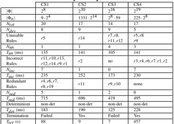
In Table 1 we report some information about the case studies and the corresponding results of the formal analysis performed using the vIRONy tool.
In detail, we report the cardinalities of the universe |Φ| and of the admissible state space |Φa|. We also give the number of analysed ECA rules Ntot, the number Ndevof
devices, the number of unusable, incorrect and redundant rules (denoted with Nun, Ninc,
Nred) detected by the tool. Furthermore, we measure the performance of the
verifica-tion procedure in terms of time. The indicators Tun, Tincand Tred, Tdet (expressed in
milliseconds) refer, respectively, to the duration time of the verification for unusability, incorrectness, redundancy, determinism and Tteris the duration time of the verification
Table 1: Formal analysis: synthesis of the results. CS1 CS2 CS3 CS4 |Φ| 28 230 216 219 |Φa| 9 · 24 1331 · 214 28 · 59 225 · 28 Ntot 20 17 14 17 Ndev 8 9 9 5 Unusable Rules r5 r14 r7, r8, r11, r12 r5, r8 r9 Nun 1 1 4 3 Tun (ms) 135 141 105 141 Incorrect Rules r11, r10, r13, r12, r14, r9, r1 r2 no r3, r4, r6, r7, r1, r2 Ninc 7 1 0 7 Tinc (ms) 235 252 173 230 Redundant Rules r4, r6, r7, r8, r19 r11 r9, r10 none Nred 5 1 2 0 Tred (ms) 715 696 419 495
Determinism non-det non-det non-det non-det
Tdet (ms) 183 190 125 228
Termination Failed Yes Failed Yes
Tter (s) 88 9 7 457
The results in Table 1 show that our approach allows for the verification of the con-sistency property of non-trivial examples that include both boolean and integer vari-ables in approximately 1 second (see [21] for further details). The table also shows that the running time for verifying the consistency does not seem to be affected by the size of the state space (compare for instance CS1 with CS2), but rather by the number of rules. In particular, among the properties of unusability, incorrectness, redundancy, the verification of redundancy is the most computationally expensive step, as the veri-fication happens for each pair of rules, and thus it requires a number of iterations that is quadratic in the number of rules to be checked. All the examples presented here are non-deterministic. The verification of this property requires a more-or-less constant time that is independent of the size of the state space and is only partially affected by the number of rules. The analysis of verification of termination requires special care: as it can be seen from the examples, the tool T2 is able to prove termination in 50% of the cases. This is expected, as proving termination is an undecidable problem. However, T2 is a sound tool and therefore, if an answer is provided, then we know that the result can be trusted. Verification of termination is a slower process if compared to the other properties. In particular, the process can take up to 10 minutes for larger examples (CS4). Moreover, it should be remarked that T2 is non-deterministic: this means that the tool may select different strategies even if it is invoked on the same example. As a result, in some cases (such as for CS4) it may happen that the tool sometimes finds a proof, and sometimes it fails with an out-of-memory or timeout error.
The evaluation is also used to assess the performance of the simulation environ-ment of vIRONy. Table 2 reports for each case study the performances of the simulator implemented in vIRONy. The performances are measured in terms of time Tsim
(ex-pressed in milliseconds), and the initial configuration of actuators is detailed for each case study (the value “F” represents “false”).
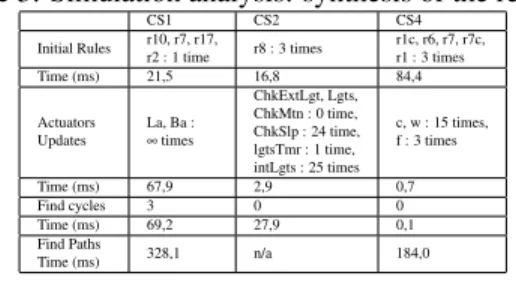
In Table 3 some of the results obtained by the semantic analysis performed on the generated simulations (ref. to Table 2) are reported. End-users can benefit from these results as they allow to analyse the system in terms of energy consumption and efficiency of the system, for a deeper understanding of the rules and the system from a quantitative perspective that is strictly linked to energy saving problems.
Table 2: Simulation: synthesis of the results. CS1 CS2 CS3 CS4 Tsim 2066 5673 359002 5030 Initial Values Bl: F, Bm: F, Bs: F, Ll: F, Lm: F, Ls: F, Ba: F, La: F lgtsTmr: 0, intLgts: -128, Lgts: F, ChkExtLgt: F, ChkMtn: F, ChkSlp: F, Mtn: F, Slp: F, ExtLgt: 0 temperature: -9, smoke: F, presenceLiving: F, sprinkler: F, heating: F, tv: F, light: F, tempAlarm: F, smokeAlarm: F c: 0, f: F, w: F, r: F, t: 0
Table 3: Simulation analysis: synthesis of the results.
CS1 CS2 CS4
Initial Rules r10, r7, r17,r2 : 1 time r8 : 3 times r1c, r6, r7, r7c,r1 : 3 times
Time (ms) 21,5 16,8 84,4 Actuators Updates La, Ba : ∞ times ChkExtLgt, Lgts, ChkMtn : 0 time, ChkSlp : 24 time, lgtsTmr : 1 time, intLgts : 25 times c, w : 15 times, f : 3 times Time (ms) 67,9 2,9 0,7 Find cycles 3 0 0 Time (ms) 69,2 27,9 0,1 Find Paths Time (ms) 328,1 n/a 184,0
6
Conclusions and future work
This paper combines different software verification techniques for modelling and ver-ifying properties of ECA rules in intelligent environments. We first define a domain-specific language (IRON) that can be employed both by developers and by end-users to program and configure an ECA rule-based system for IE. The expressivity of IRON en-ables the application of high performance methods for verifying certain requirements that are specific for ECA-rule based systems for IE. We have implemented our ap-proach in the open source tool vIRONy that has been validated by considering four cases studies from the literature. As future work we plan to add into our system data analysis in order to discover the global properties of the system. This rules will be encoded in iron and will be formally verified [33, 34, 35].
References
[1] J.C. Augusto and A. Coronato, Introduction to the inaugural issue of the Jour-nal of Reliable Intelligent Environments, JourJour-nal of Reliable Intelligent Environ-ments1(1) (2015), 1–10, ISSN 2199-4676.
[2] K. Schneider, Verification of Reactive Systems: Formal Methods and Algorithms, SpringerVerlag, 2004. ISBN ISBN 3540002960.
[3] V. Callaghan, G. Clarke, M. Colley, H. Hagras, J.S.Y. Chin and F. Doctor, Inhab-ited Intelligent Environments, BT Technology Journal 22(3) (2004), 233–247. [4] G. Russello, L. Mostarda and N. Dulay, A policy-based publish/subscribe
mid-dleware for sense-and-react applications, Journal of Systems and Software 84(4) (2011), 638–654.
[5] J.C. Augusto and M.J. Hornos, Using Simulation and Verification to Inform the Development of Intelligent Environments., in: Intelligent Environments (Work-shops), 2012, pp. 413–424.
[6] F. Kausar, E. Al Eisa and I. Bakhsh, Intelligent Home Monitoring Using RSSI in Wireless Sensor Networks, International Journal of Computer Networks & Communications4(6) (2012), 33.
[7] Y. Sun, X. Wang, H. Luo and X. Li, Conflict Detection Scheme Based on Formal Rule Model for Smart Building Systems, IEEE Transactions on Human-Machine Systems45(2) (2015), 215–227.
[8] D. Preuveneers and W. Joosen, Change Impact Analysis for Context-Aware Ap-plications in Intelligent Environments, in: Intelligent Environments, 2015. [9] G.J. Myers, C. Sandler and T. Badgett, The art of software testing, John Wiley &
Sons, 2011.
[10] X. Jin, Y. Lembachar and G. Ciardo, Symbolic verification of ECA rules, in: Joint Proc. of the Int. Workshop on Petri Nets and Software Eng. and the Int. Workshop on Modeling and Business Env. (ModBE’13), 2013, pp. 41–59.
[11] T. Murata, Petri nets: Properties, analysis and applications, Proceedings of the IEEE77(4) (1989), 541–580.
[12] D. Beyer and A. Stahlbauer, BDD-based software verification, International Jour-nal on Software Tools for Technology Transfer16(5) (2014), 507–518.
[13] S.B. Akers, Binary decision diagrams, IEEE Transactions on computers 100(6) (1978), 509–516.
[14] J. Cano, G. Delaval and E. Rutten, Coordination Models and Languages: COOR-DINATION 2014, E. K¨uhn and R. Pugliese, eds, 2014, pp. 33–48, Chap. Coordi-nation of ECA Rules by Verification and Control.
[15] G. Delaval, ´E. Rutten and H. Marchand, Integrating discrete controller synthesis into a reactive programming language compiler, Discrete Event Dynamic Systems 23(4) (2013), 385–418.
[16] A. Ericsson, Enabling Tool Support for Formal Analysis of ECA Rules, PhD thesis, University of Sk¨ovde, 2009.
[17] J. Bengtsson, K. Larsen, F. Larsson, P. Pettersson and W. Yi, UPPAAL?a tool suite for automatic verification of real-time systems, in: Hybrid Systems III, Springer, 1996, pp. 232–243.
[18] F. Corradini, R. Culmone, L. Mostarda, L. Tesei and F. Raimondi, A Constrained ECA Language Supporting Formal Verification of WSNs, in: Advanced Informa-tion Networking and ApplicaInforma-tions Workshops (WAINA), 2015 IEEE 29th Interna-tional Conference on, 2015, pp. 187–192.
[19] C. Vannucchi, D.R. Cacciagrano, F. Corradini, R. Culmone, L. Mostarda, F. Rai-mondi and L. Tesei, A Formal Model for Event-Condition-Action Rules in In-telligent Environments, in: Proceedings of the 11th International Conference on Intelligent Environments, 2016, pp. 56–65.
[20] L. Mostarda, S. Marinovic and N. Dulay, Distributed Orchestration of Pervasive Services, in: 24th IEEE IAINA 2010, Perth, Australia, 20-13 April 2010, 2010, pp. 166–173.
[21] C. Vannucchi, M. Diamanti, G. Mazzante, D. Cacciagrano, R. Culmone, N. Goro-giannis, L. Mostarda and F. Raimondi, Symbolic verification of event–condition– action rules in intelligent environments, Journal of Reliable Intelligent Environ-ments(2017), 1–14.
[22] M.O. Rabin and D. Scott, Finite automata and their decision problems, IBM jour-nal of research and development3(2) (1959), 114–125.
[23] M. Brockschmidt, B. Cook and C. Fuhs, Better termination proving through coop-eration, in: International Conference on Computer Aided Verification, Springer, 2013, pp. 413–429.
[24] B. Cook and E. Koskinen, Reasoning about nondeterminism in programs, ACM SIGPLAN Notices48(6) (2013), 219–230.
[25] B. Cook, A. See and F. Zuleger, Ramsey vs. lexicographic termination proving, in: International Conference on Tools and Algorithms for the Construction and Analysis of Systems, Springer, 2013, pp. 47–61.
[26] B. Cook, A. Podelski and A. Rybalchenko, TERMINATOR: beyond safety, in: In-ternational Conference on Computer Aided Verification, Springer, 2006, pp. 415– 418.
[27] C. Barrett, A. Stump, C. Tinelli, S. Boehme, D. Cok, D. Deharbe, B. Dutertre, P. Fontaine, V. Ganesh, A. Griggio, J. Grundy, P. Jackson, A. Oliveras, S. Krsti, M. Moskal, L.D. Moura, R. Sebastiani, T.D. Cok and J. Hoenicke, C.: The SMT-LIB Standard: Version 2.0, Technical Report, 2010.
[28] L. De Moura and N. Bjørner, Satisfiability modulo theories: An appetizer, in: Brazilian Symposium on Formal Methods, Springer, 2009, pp. 23–36.
[29] E.W. Dijkstra, Guarded Commands, Nondeterminacy and Formal Derivation of Programs, Commun. ACM 18(8) (1975), 453–457.
[30] D. Gries, The Science of Programming, Monographs in Computer Science, Springer, 1989.
[31] L. De Moura and N. Bjørner, Z3: An Efficient SMT Solver, in: Proceedings of the Theory and Practice of Software, 14th Int. Conf. on Tools and Algorithms for the Construction and Analysis of Systems, TACAS’08/ETAPS’08, 2008, pp. 337– 340.
[32] C. Vannucchi, D.R. Cacciagrano, R. Culmone and L. Mostarda, Towards a Uniform Ontology-Driven Approach for Modeling, Checking and Executing WSANs, 2016 30th International Conference on Advanced Information Network-ing and Applications Workshops (WAINA)(2016), 319–324.
[33] E. Merelli, M. Pettini and M. Rasetti, Topology driven modeling: the IS metaphor, Natural Computing14(3) (2015), 421–430.
[34] E. Merelli, M. Rucco, P.M.A. Sloot and L. Tesei, Topological Characterization of Complex Systems: Using Persistent Entropy, Entropy 17(10) (2015), 6872–6892. [35] E. Bartocci, D. Cacciagrano, N. Cannata, F. Corradini, E. Merelli, L. Milanesi
and P. Romano, An agent-based multilayer architecture for bioinformatics grids, IEEE Transactions on Nanobioscience6(2) (2007), 142–148.
[36] M. Berndtsson and J. Mellin, ECA Rules, in: Encyclopedia of Database Systems, L. LIU and M.T. ¨OZSU, eds, Springer US, 2009, pp. 959–960.