Università della Calabria
Dipartimento di Ingegneria per l'Ambiente e il Territorio e Ingegneria Chimica Dottorato in Scienze ed Ingegneria dell'Ambiente, delle Costruzioni e dell’EnergiaPh.D. Dissertation
Mass and momentum transfer in membrane-based
bioartificial liver systems
Ph.D. Candidate:
Shervin Khakpour
Supervisors:
Dr. Loredana De Bartolo
Prof. Efrem Curcio
This research was funded by:
Marie Skłodowska-Curie Actions
Initial Training Network
Project “BIOART”
Training network for developing innovative (bio)artificial devices for
treatment of kidney and liver disease
(Grant no.316690, EU-FP7-PEOPLE-ITN-2012)
To my parents
Contents
LIST OF FIGURES ... I LIST OF TABLES ... VI ACKNOWLEDGEMENTS ... VII ABSTRACT ... VIII ABSTRACT ... XI NOMENCLATURE ... XV CHAPTER 1 STATE OF THE ART AND AIM OF THE WORK ... 18 1.1 LIVER ANATOMY AND FUNCTIONS ... 18 1.2 LIVER FAILURE AND TREATMENT MODALITIES ... 20 1.3 ARTIFICIAL LIVER DEVICES ... 21 1.4 BIOARTIFICIAL LIVER SYSTEMS ... 22 1.5 MEMBRANE-BASED BIOREACTORS FOR IN VITRO CELL CULTURES ... 24 1.5.1 FLAT PLATE MEMBRANE BIOREACTORS ... 24 1.5.2 HOLLOW FIBER MEMBRANE BIOREACTORS ... 25 1.6 BIOARTIFICIAL LIVER SYSTEMS IN CLINICAL TRIAL ... 26 1.7 OTHER BIOREACTOR DESIGNS FOR IN VITRO HEPATIC CULTURE STUDIES ... 27 1.8 CHALLENGES IN BIOREACTOR DESIGN ... 29 1.8.1 MEMBRANES ... 30 1.8.2 TRANSPORT PHENOMENA ... 32 1.9 ABOUT CURRENT RESEARCH STUDY ... 35 1.9.1 MOTIVATION ... 35 1.9.2 OBJECTIVE ... 36 1.9.3 APPROACH ... 38 REFERENCES ... 40 CHAPTER 2 FLUID DYNAMICS AND PERMEABILITY IN THE MEMBRANE BIOREACTOR ... 46 2.1 INTRODUCTION ... 46 2.2 MATERIALS AND METHODS ... 47 2.2.1 HOLLOW FIBER PERMEABILITY TESTS ... 47 2.2.2 BIOREACTOR FLUID DYNAMICS ... 49 2.2.3 STATIC SYSTEM ... 51 2.3 RESULTS ... 53 2.3.1 HOLLOW FIBERS ... 53 2.3.2 BIOREACTOR ... 54 2.3.3 STATIC SYSTEM ... 55 2.4 DISCUSSION ... 57 2.5 CONCLUSIONS ... 59 REFERENCES ... 60CHAPTER 3 OXYGEN TRANSFER MODEL IN STATIC CULTURE SYSTEMS ... 61 3.1 INTRODUCTION ... 61 3.2 METHODS ... 62 3.2.1 MATHEMATICAL MODEL ... 62 3.2.2 BOUNDARY CONDITIONS ... 64 3.3 RESULTS ... 65 3.3.1 SPHEROIDS ... 65 3.3.2 CELLULAR LAYER ... 69 3.4 DISCUSSION ... 71 3.5 CONCLUSIONS ... 72 REFERENCES ... 73 CHAPTER 4 MASS TRANSFER MODEL FOR HOLLOW FIBER MEMBRANE BIOREACTORS ... 74 4.1 INTRODUCTION ... 74 4.2 MATHEMATICAL MODEL ... 74 4.3 GEOMETRY AND BOUNDARY CONDITIONS ... 78 4.3.1 SINGLE-SPHEROID MODEL ... 78 4.3.2 MINIATURIZED BIOREACTOR ... 80
4.4 IMPLEMENTATION IN COMSOL MULTIPHYSICS ... 81
4.5 RESULTS ... 82 4.5.1 DEPENDENT VARIABLES ... 82 4.5.2 MESH SENSITIVITY ... 82 4.5.3 EXTENDED ELEMENT: MODEL VALIDITY ... 84 4.6 DISCUSSION ... 84 4.7 CONCLUSION ... 87 REFERENCES ... 88 CHAPTER 5 EFFECT OF DIFFERENT PARAMETERS ON OXYGEN TRANSPORT ... 90 5.1 INTRODUCTION ... 90 5.2 MATERIALS AND METHODS ... 91 5.3 RESULTS ... 93 5.4 DISCUSSION ... 98 5.5 CONCLUSION ... 102 REFERENCES ... 103 CHAPTER 6 ESTABLISHMENT OF IN VIVO-LIKE OXYGEN GRADIENT INSIDE THE SPHEROIDS CULTURED IN THE BIOREACTOR ... 104 6.1 INTRODUCTION ... 104 6.2 MATERIALS AND METHODS ... 105 6.2.1 MATHEMATICAL MODEL ... 105
6.2.2 EXPERIMENTAL PROCEDURE ... 106
6.3 RESULTS ... 107
6.3.1 MAINTAINING PHYSIOLOGICAL DOC RANGE IN VITRO ... 107
6.3.2 OXYGEN SUPPLY TO A SHRINKING HEPATOCYTE SPHEROID: CONSTANT NUMBER OF CELLS ... 110 6.3.3 MODEL BASED ON EXPERIMENTAL DATA ... 111 6.4 DISCUSSION ... 114 6.5 CONCLUSION ... 115 REFERENCES ... 116 CHAPTER 7 MASS TRANSFER IN MINIATURIZED BIOREACTOR ... 118 7.1 INTRODUCTION ... 118 7.2 METHODS ... 119 7.2.1 APPROACH ... 119 7.2.2 MINIATURIZED BIOREACTOR MODEL: SCALING DOWN PROCEDURE ... 119 7.3 RESULTS ... 121 7.3.1 EFFECT OF MINIMIZING THE STAGNANT REGION ON OXYGEN TRANSFER ... 124 7.3.2 EFFECT OF RETENTATE FLOW ON OXYGEN TRANSFER ... 127 7.3.3 EFFECT OF FLOW PATTERN AND FLUID DYNAMICS ... 129 7.3.4 MODEL BASED ON EXPERIMENTAL DATA ... 135 7.4 DISCUSSION ... 137 7.5 CONCLUSIONS ... 139 REFERENCES ... 139 CHAPTER 8 CONCLUSIONS AND FUTURE DIRECTIONS ... 140 8.1 SUMMARY OF CONTRIBUTIONS ... 140 8.2 RECOMMENDATIONS FOR FUTURE WORK ... 142 APPENDIX 1: FLUIDIZED-BED BIOREACTOR ... 147 1. INTRODUCTION ... 147 2. METHODS ... 148 2.1 ALGINATE BEADS PREPARATION ... 148 2.2 FLUIDIZATION ... 149 2.3 BEADS’ SWELLING OVER TIME ... 150 2.4 BEADS’ FALLING VELOCITY ... 151 2.5 MASS TRANSPORT INTO THE BEADS ... 151 3. RESULTS ... 153 4. DISCUSSION ... 155 5. CONCLUSIONS ... 158 REFERENCES ... 159
i
List of figures
Figure 1. 1 (Top) Macroanatomy of the liver. (Bottom) Microanatomy of the liver, showing a hepatic lobule. Image source:
https://cms.webstudy.com/WebstudyFileSystem/testovaci/GetFile/293875/Ch%2022/Ch22b /Ch22b_print.html
Figure 1. 2 Hepatic zonation and distribution of functions along the sinusoid [5].
Figure 1. 3 Common types of BAL devices and areas in which they are mostly employed [12]. Figure 1. 4 Examples of bioreactors used for in vitro studies. (a) Oxygen-permeable
flat-membrane bioreactor [De Bartolo et al. 2006], (b) Crossed hollow fiber flat-membrane bioreactor [De Bartolo et al. 2009].
Figure 1. 5 Compartmentalization of the membrane-based BALs. Bidirectional mass transfer occurs between the compartments and through the membranes. The concentration gradient trends shown apply to diffusion-controlled mass transfer and are merely qualitative, since the rate and extent of the gradients differ for each component.
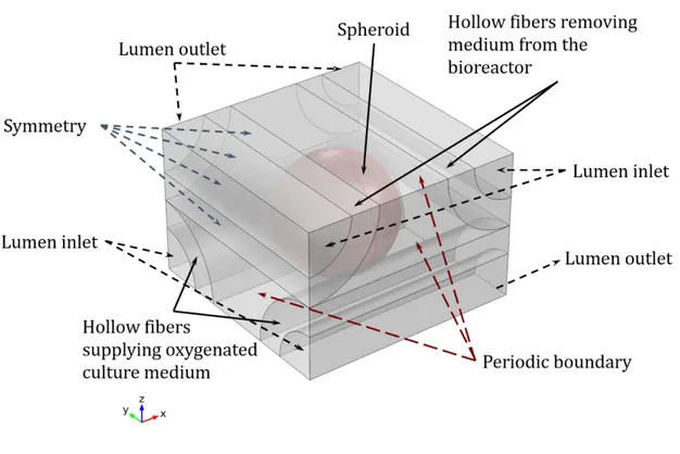
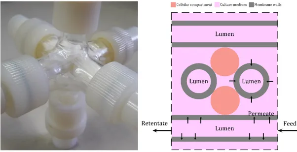
Figure 1. 6 Crossed-Configuration hollow fiber membrane bioreactor used in this study. (Left) assembled bioreactor for illustration purposes, (Right) schematic illustration of the
bioreactor, showing the existing compartments.
Figure 1. 7 (Top) Assembled circuit and connections used to run the bioreactor. (Bottom) Process flow diagram showing bioreactor's connections during culture.
Figure 2. 1 Hollow fiber module assembled for permeability measurements (25 PEEK-WC hollow fibers, 5x5 arrangement).
Figure 2. 2 Process flow diagram for testing hydraulic permeability and albumin permeability. Figure 2. 3 Experimental setup for residence time distribution analysis for the bioreactor. The
reservoirs for water and tracer are not shown in the picture (on the right side).
Figure 2. 4 Process flow diagram for residence time distribution analysis in the bioreactor. Figure 2. 5 OxoDish® and SensorDish® Reader used for the experiment.
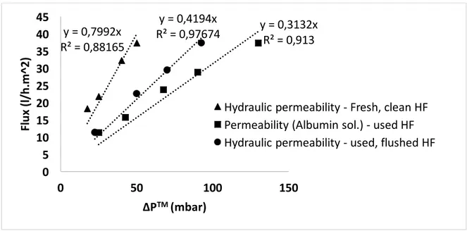
Figure 2. 6 Geometry and boundary conditions for numerical analysis. Figure 2. 7 Permeability study on PEEK-WC hollow fibers.
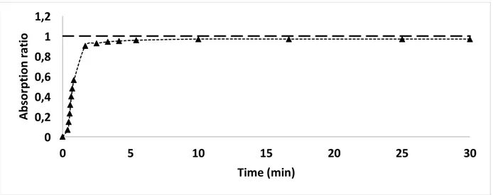
Figure 2. 8 Cout/Cmax ratio as a function of time, known as the F curve, for albumin permeance experiment.
Figure 2. 9 E and 1-F curves for ideal mixed flow model [5].
Figure 2. 10 1-F (top) and E (bottom) curves for experimental results in comparison with the ideal mixed flow (CSTR) model.
Figure 2. 11 Oxygen concentrations at the bottom of the well (averaged over 4 wells for each condition) recorded over 14.3 hours after changing the oxygen partial pressure in the incubator from 20% to 10%.
Figure 2. 12 Comparison between the experimental and theoretical values for oxygen
concentrations at the bottom of the well after changing the oxygen tension in the incubator from 20% to 10%..
ii
Figure 2. 13 E and 1-F curves for the compartment flow model of mixed flow region + stagnant region [1].
Figure 2. 14 E and 1-F curves for experimental results in comparison with the compartment flow model of mixed flow region + stagnant region.
Figure 3. 1 (Left) Geometry of a single well considered for mass transfer modelling. (Right) arrangement of 99 spheroids at the bottom of the well, and the spheroids for which the oxygen concentration profile will be given in more detail. For reducing the computational time, the geometry was divided in half considering an x-z symmetric plane.
Figure 3. 2 Boundary conditions applied for mass transfer modelling (n is the boundary’s normal vector).
Figure 3. 3 Oxygen concentration profile (mol/m³) in a well containing 1ml of culture medium and 99 spheroids (200µm in diameter with 50µm space between them).
Figure 3. 4 Oxygen concentration profile (mol/m³) inside the spheroids sitting at the bottom of a well containing 1ml of culture medium and 99 spheroids (200µm in diameter, 50µm
spacing).
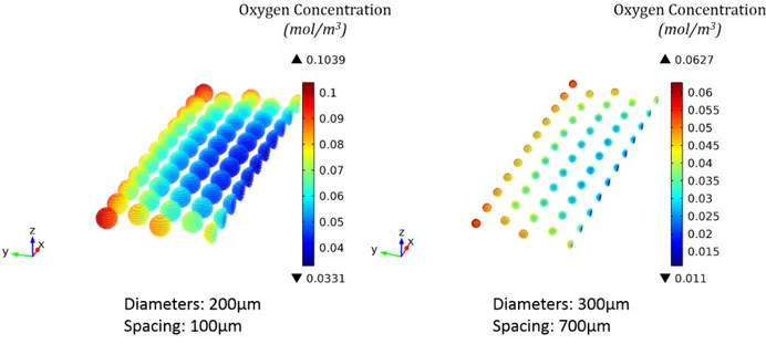
Figure 3. 5 Oxygen concentration profile (mol/m³) inside the spheroids sitting at the bottom of a well containing 1ml of culture medium and 99 spheroids (200µm in diameter, 100µm spacing).
Figure 3. 6 Oxygen concentration profile (mol/m³) inside the spheroids sitting at the bottom of a well containing 1ml of culture medium and 30 spheroids 300µm in diameter (300µm
spacing) having the same total number of cells as in 100 spheroids 200µm in diameter. Figure 3. 7 Oxygen concentration profile (mol/m³) inside the spheroids sitting at the bottom of a
well containing 1ml of culture medium and 99 spheroids (300µm in diameter, 700µm spacing).
Figure 3. 8 Oxygen concentration profile (mol/m³) inside the spheroids sitting at the bottom of a well containing 2ml of culture medium.
Figure 3. 9 Oxygen concentration profile (mol/m³) in a well containing 1ml of culture medium and a cellular monolayer with 16µm thickness and 2.89mm radius having the same total number of cells as in 99 spheroids 200µm in diameter. (Top) Concentration profile through the medium, (Bottom) concentration profile across the cellular layer.
Figure 3. 10 Oxygen concentration profile (mol/m³) in a well containing 1ml of culture medium and a cellular monolayer fully covering the bottom of the well (16µm thickness). Oxygen concentration in the cellular layer is 0.0432 – 0.0442 mol/m³.
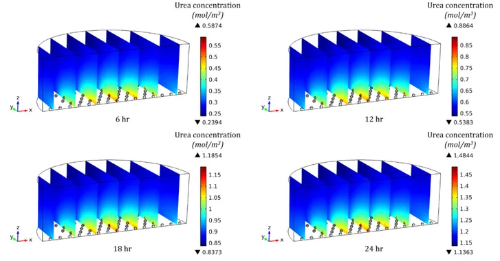
Figure 3. 11 Urea concentration profile and its accumulation in 1ml culture medium containing 99 spheroids (300µm in diameter, 700µm spacing) at different time points during the culture.
Figure 4. 1 Single-spheroid model: periodic unit element (750×750×500 µm) representative of the bioreactor configuration.
Figure 4. 2 Miniaturized bioreactor model considering 9 hollow fibers in each bundle, hosting 20 spheroids in a 4×4×5 arrangement in the extra-capillary space.
iii
Figure 4. 3 Velocity (top), pressure (center) and concentration (bottom) profiles in the single-spheroid model.
Figure 4. 4 Dissolved oxygen concentration inside the spheroids in single-spheroid model obtained by using different physics-contolled default mesh sizes in COMSOL Multiphysics. (a) Coarser, (b) Coarse, (c) Normal, (d) Fine, (e) Finer, (f) Extra fine.
Figure 4. 5 Extended periodic unit element consisting of 36 spheroids
Figure 5. 1 Minimum and maximum DOC within the spheroid for different saturated DOCs and spheroid porosities.
Figure 5. 2 Minimum and maximum DOC within the spheroid for different perfusion rates and spheroid porosities.
Figure 5. 3 Minimum and maximum DOC within the spheroid for different spheroid diameters and porosities.
Figure 5. 4 Minimum and maximum DOC within the spheroid for different inter-HF spacing and spheroid porosities.
Figure 5. 5 Minimum and maximum DOC within the spheroid for different Vmax and spheroid porosities.
Figure 5. 6 Minimum and maximum DOC within the spheroid, and oxygen transfer rate into the spheroid for different intra-spheroid porosities.
Figure 5. 7 Minimum and maximum DOC within the spheroid for different membrane and spheroid porosities.
Figure 6. 1 DOC profile (µmol/L) in the ECS (left) and inside the spheroid (right) for
Dsph=400µm and εcc=0.20. (Co,sat=185 µmol/L, QBR=1 ml/min, Vmax=5 nmol/(s.cm³), Km=5.6 mm Hg, εm=0.7, δHF=250µm.)
Figure 6. 2 Proportion and position of the cells exposed to physiological DOC range within the spheroid with Dsph=400µm and εcc=0.20. (Co,sat=185 µmol/L, QBR=1 ml/min, Vmax=5 nmol/(s.cm³), Km=5.6 mm Hg, εm=0.7, δHF=250µm.)
Figure 6. 3 Shear (left) and normal total (right) stress exerted on the spheroid surface of the spheroid the spheroid with Dsph=400µm and εcc=0.20. (Co,sat=185 µmol/L, QBR=1 ml/min, Vmax=5 nmol/(s.cm³), Km=5.6 mm Hg, εm=0.7, δHF=250µm.)
Figure 6. 4 DOC profile (mol/m3) in the ECS (left) and inside the spheroid (right) for
Dsph=400µm and εcc=0.47. (Co,sat=115 µmol/L, QBR=1 ml/min, Vmax=5 nmol/(s.cm³), Km=5.6 mm Hg, εm=0.7, δHF=250µm.)
Figure 6. 5 (Left) DOC profile (mol/m3) in the spheroid before shrinkage. Dsph=400µm and εcc=0.42. (Right) DOC profile (mol/m3) in the spheroid after shrinkage. Dsph=360µm and εcc=0.20. Other parameters remain unaltered for both cases: Co,sat=130 µmol/L,
QBR=0.8m.
Figure 6. 6 Primary hepatocyte spheroids between hollow fibers. (Left) Separate adjacent spheroids, (Right) Spheroids merging together to from larger cellular masses.
Figure 6. 7 DOC profile (mol/m3) inside the spheroid (left) and in the ECS (right) for Dsph=200µm and εcc=0.41. (Co,sat=224 µmol/L, QBR=0.6 ml/min, Vmax=17
iv
Figure 6. 8 DOC profile (mol/m3) inside the spheroid (left) and in the ECS (right) for Dsph=363µm and εcc=0.41. (Co,sat=224 µmol/L, QBR=0.6 ml/min, Vmax=17 nmol/(s.cm³), Km=5.6 mm Hg, εm=0.8, δHF=250µm).
Figure 7. 1 miniaturized bioreactor considering 9 hollow fibers in a 3x3 arrangement. Figure 7. 2 Cubic bioreactor considering 9 hollow fibers in a 3x3 arrangement.
Figure 7. 3 Oxygen concentration in the spheroids, supplying-removing flow pattern. Dsph=400
µm, Co,sat=185 µmol/L, QBR=1 ml/min, Vmax=25 nmol/(s.cm³), Km=5.6 mm Hg, εcc=0.42,
εm=0.7.
Figure 7. 4 Oxygen concentration in the extra-capillary space, supplying-removing flow pattern. Dsph=400 µm, Co,sat=185 µmol/L, QBR=1 ml/min, Vmax=25 nmol/(s.cm³), Km=5.6 mm Hg,
εcc=0.42, εm=0.7.
Figure 7. 5 Oxygen concentration in the lumina, supplying-removing flow pattern. Dsph=400
µm, Co,sat=185 µmol/L, QBR=1 ml/min, Vmax=25 nmol/(s.cm³), Km=5.6 mm Hg, εcc=0.42,
εm=0.7.
Figure 7. 6 Urea concentration in the bioreactor, supplying-removing flow pattern. Dsph=400
µm, QBR=1 ml/min, εcc=0.42, εm=0.7.
Figure 7. 7 Oxygen concentration in the spheroids for a cubic bioreactor, supplying-removing flow pattern. Dsph=400 µm, Co,sat=185 µmol/L, QBR=1 ml/min, Vmax=25 nmol/(s.cm³),
Km=5.6 mm Hg, εcc=0.42, εm=0.7.
Figure 7. 8 Oxygen concentration and Peclet number in the extra-capillary space for a cubic bioreactor, supplying-removing flow pattern. Dsph=400 µm, Co,sat=185 µmol/L, QBR=1
ml/min, Vmax=25 nmol/(s.cm³), Km=5.6 mm Hg, εcc=0.42, εm=0.7.
Figure 7. 9 Oxygen concentration and Peclet number in the lumina for a cubic bioreactor, supplying-removing flow pattern. Dsph=400 µm, Co,sat=185 µmol/L, QBR=1 ml/min,
Vmax=25 nmol/(s.cm³), Km=5.6 mm Hg, εcc=0.42, εm=0.7.
Figure 7. 10 Oxygen concentration in the spheroids in the bioreactor with a retentate flow is present, supplying-removing flow pattern. Dsph=400 µm, Co,sat=185 µmol/L, QBR=1 ml/min,
Vmax=25 nmol/(s.cm³), Km=5.6 mm Hg, εcc=0.42, εm=0.7.
Figure 7. 11 Oxygen concentration and Peclet number in the extra-capillary space of the bioreactor with a retentate flow is present, supplying-removing flow pattern. Dsph=400 µm,
Co,sat=185 µmol/L, QBR=1 ml/min, Vmax=25 nmol/(s.cm³), Km=5.6 mm Hg, εcc=0.42,
εm=0.7.
Figure 7. 12 Oxygen concentration and Peclet number in the lumina of the bioreactor with a retentate flow is present, supplying-removing flow pattern. Dsph=400 µm, Co,sat=185
µmol/L, QBR=1 ml/min, Vmax=25 nmol/(s.cm³), Km=5.6 mm Hg, εcc=0.42, εm=0.7.
Figure 7. 13 Oxygen concentration in the spheroids, both bundles supplying the culture medium. Dsph=400 µm, Co,sat=185 µmol/L, QBR=1 ml/min, Vmax=25 nmol/(s.cm³), Km=5.6
mm Hg, εcc=0.42, εm=0.7.
Figure 7. 14 Oxygen concentration in the extra-capillary space, both bundles supplying the culture medium. Dsph=400 µm, Co,sat=185 µmol/L, QBR=1 ml/min, Vmax=25 nmol/(s.cm³),
Km=5.6 mm Hg, εcc=0.42, εm=0.7.
Figure 7. 15 Oxygen concentration in the lumina, both bundles supplying the culture medium. Dsph=400 µm, Co,sat=185 µmol/L, QBR=1 ml/min, Vmax=25 nmol/(s.cm³), Km=5.6 mm Hg,
v
Figure 7. 16 Urea concentration in the bioreactor, both bundles supplying the culture medium. Dsph=400 µm, QBR=1 ml/min, εcc=0.42, εm=0.7.
Figure 7. 17 Oxygen concentration in the spheroids, both bundles removing the culture medium. Dsph=400 µm, Co,sat=185 µmol/L, QBR=1 ml/min, Vmax=25 nmol/(s.cm³), Km=5.6
mm Hg, εcc=0.42, εm=0.7.
Figure 7. 18 Oxygen concentration in the extra-capillary space, both bundles removing the culture medium. Dsph=400 µm, Co,sat=185 µmol/L, QBR=1 ml/min, Vmax=25 nmol/(s.cm³), Km=5.6 mm Hg, εcc=0.42, εm=0.7.
Figure 7. 19 Oxygen concentration in the lumina, both bundles removing the culture medium. Dsph=400 µm, Co,sat=185 µmol/L, QBR=1 ml/min, Vmax=25 nmol/(s.cm³), Km=5.6 mm Hg,
εcc=0.42, εm=0.7.
Figure 7. 20 Urea concentration in the bioreactor, both bundles removing the culture medium. Dsph=400 µm, QBR=1 ml/min, εcc=0.42, εm=0.7.
Figure 7. 21 F (top) and E (bottom) curves used in residence time distribution analysis, obtained through modelling for three different flow patterns.
Figure 7. 22 (Left) Oxygen concentration in the spheroids, supplying-removing pattern, 6 spheroids per ECS unit, (Right) oxygen concentration in the ECS. Dsph=200 µm,
Co,sat=224 µmol/L, QBR=0.6 ml/min, Vmax=17 nmol/(s.cm³), Km=5.6 mm Hg, εcc=0.41, εm=0.8.
Figure 7. 23 (Left) Oxygen concentration in the merged 6 spheroids, supplying-removing pattern. (Right) Oxygen concentration in the ECS. Equivalent Dsph=363 µm, Co,sat=224 µmol/L, QBR=0.6 ml/min, Vmax=17 nmol/(s.cm³), Km=5.6 mm Hg, εcc=0.41, εm=0.8. Figure 7. 24 (Left) Oxygen concentration in the spheroids based on scaling down seeded cell
number, supplying-removing pattern. (Right) Oxygen concentration in the ECS. Equivalent Dsph=359 µm, Co,sat=224 µmol/L, QBR=0.6 ml/min, Vmax=17 nmol/(s.cm³), Km=5.6 mm Hg, εcc=0.41, εm=0.8.
vi
List of tables
Table 5. 1 Parameters, their default value and the range over which they were investigated in the parametric study.
Table 5. 2 Dimensionless parameters used for evaluation of oxygen transfer in the HFMBR. Table 5. 3 Dimensionless numbers for the default values of the parameters under study reported
vii
Acknowledgements
First and foremost, I would like to sincerely and wholeheartedly thank my main supervisor, Dr. Loredana De Bartolo for her full support and encouragement, and giving me the opportunity to work on a very interesting and challenging research area. I especially appreciate her dedication of time to share her vast expertise in the field and always introduce me to new topics.
I extend my deepest gratitude to Dr. Alberto Di Renzo for his generous guidance and support through the modelling work, provision of the computational means and his meticulous consultations. I was very lucky to benefit from his knowledge as well as his approaches in tackling the complications of the work.
Very special thanks to Prof. Efrem Curcio for his supervision, exchange of ideas during the meetings and insightful notions regarding the direction and drafting of the work. I really appreciate his support, attitude and morale.
Many people helped and supported me from different groups in ITM-CNR and University of Calabria. In particular, I would like to thank Prof. Francesco Paolo Di Maio for his insightful ideas and suggestions on modelling aspects. I am ever so grateful to Dr. Simona Salerno, who always patiently helped me on all the experimental and lab work. I also extend my appreciation to Dr. Franco Tasselli, for preparation and explanation of specific hollow fibers.
I would like to express my sincere gratitude to Dr. Lidieta Giorno, the director of ITM-CNR, for always helping with work-related issues, exceptional management, and all the friendly chats. I acknowledge Marie Skłodowska-Curie Actions for financial support of this research. I extend my appreciation to all the wonderful people involved in BIOART project. I was fortunate to learn a lot from the supervisors and form memorable friendships with the fellows. I would like to especially thank the coordinator of the project, Prof. Dimitrios Stamatialis, and Prof. Cecile Legallais for arranging my very educational and invaluable secondment in University of Technology of Compiègne. Big thanks to Marie Curie fellows and great friends Haysam Ahmed and Seyed Danial Naghib, with whom I had enjoyable talks and discussions on a daily basis. I dedicate this to my beloved family, to whom I am eternally grateful. I could not be where I am now without my parents’ tremendous support, always encouraging me to move forward.
viii
Abstract
Liver failure, caused by acute or chronic end-stage liver disease (ESLD) imposes a significant disease burden worldwide. Chronic liver disease and cirrhosis is ranked as 12th cause of death in the United States and 4th in middle-aged adults. Researchers in Mayo Clinic report liver-related mortality as 8th by using a more comprehensive definition accounting for other aspects of liver disease as well. Currently, liver transplantation remains the conventional treatment for ESLD as the only medically proven method to promote patient’s health. To avoid the problem of inadequate donor organs and yet provide a comprehensive range of liver functions, cell-based therapies have been actively under investigation to potentially provide a substitute for transplantation, or a temporary support for liver failure patients. Studies on the latter aim has led to development of extracorporeal bioartificial liver (BAL) devices.
Hepatic cell cultures are exploited for different applications in liver disease studies, drug toxicity testing, and bioartificial liver (BAL) devices. However, development of such systems is often hindered by the peculiar characteristics and intricate requirements of primary hepatocytes, challenging their prolonged functionality and viability in vitro. Despite the development of various 3D cell culture systems using perfused bioreactors, mass transfer properties still remain a critical and controversial topic, especially oxygen supply as the limiting and modulating factor.
The aim of this work is to enhance and optimize a prototype hollow fiber membrane bioreactor (HFMBR) providing efficient mass transfer for nutrient provision and catabolite removal, promoting prolonged viability and functionality of hepatocytes. In this bioreactor, two bundles of hollow fibers are employed in a crossed configuration: one bundle for supplying the oxygenated medium, and the other for removing the medium from the extra-capillary space. Optimization of the operational culture conditions to enforce an in vivo-like microenvironment is an intrinsic part of the process that requires a clear understanding of the in vitro cellular microenvironment. Oxygen transport in a convection-enhanced, crossed-configuration HFMBR hosting hepatocyte spheroids was investigated through mass transfer modelling using COMSOL Multiphysics®, a specialized, commercial finite-element software.
The permeability of hollow fibers (hydraulic, albumin solution) was evaluated experimentally, showing significant, irreversible decrease in the permeance of the membranes due to protein absorption during culture period. Bioreactor’s hydrodynamics was investigated through residence
ix
time distribution analysis, by which a portion of the bioreactor was diagnosed as stagnant region. Finally, oxygen diffusion through the medium and the effect of different conditionings on the oxygen sensor’s readings in multi-well plates were studied.
Mass transfer in static culture systems – both as a monolayer and as spheroids – was evaluated using a diffusion-reaction model numerically solved for oxygen (steady-state study) and urea (time-dependent study). In addition to the size and number of spheroids, sufficiency of oxygen supply to cells also depended on their distribution (the distance between them) and the amount of culture medium in each well.
A convection-diffusion-reaction model was developed to describe momentum and mass transfer in the bioreactor, in which the influential parameters were parametrized through implementation of applicable correlations. The model was numerically solved for two different types of geometries: (i) single-spheroid model using a periodic/symmetric unit cell within the bioreactor to locally represent the system decreasing the computational complexity of the model, (ii) miniaturized bioreactor model.
The single-spheroid model was used to carry out a systematic parametric study to evaluate the effect of different parameters – oxygen tension (Co,sat), perfusion rate (QBR), hollow fiber spacing
(δHF), spheroid diameter (Dsph), Michaelis-Menten kinetics for oxygen uptake (Vmax, Km) and
porosities of the spheroid (εcc) and the membrane (εm) – on dissolved oxygen concentration (DOC)
profile. Dimensionless numbers were defined for in-depth analysis of oxygen transfer and how each parameter can affect that. Among the operational conditions, Co,sat was found much more
influential than QBR. Due to the mild advection added, the extra-spheroid resistances to diffusive
mass transfer, i.e. the membrane (governed by εm) remains an important factor. However, εcc was
found as a key intrinsic property strongly affecting intra-spheroid DOC profile.
Maintaining physiological DOC range in large spheroids (Dsph=400µm) with different porosities
was investigated in the single-spheroid model. Regulation of DOC profile was more manageable in spheroids with higher εcc, which lead to feasibility of achieving physiological oxygen
concentrations. Low-porosity spheroids demonstrated a sharper concentration gradient, challenging sufficient oxygen supply to cells.
Temporal shrinkage of spheroids due to rearrangement of cells changes the microstructure of the spheroid, the effect of which was numerically studied and proved to adversely affect the transport
x
properties and consequently the DOC profile inside the spheroid. In the end, values from an experimental study were incorporated into the model to analyze the cellular microenvironment during the experiment, and the predictive capacity of the model regarding the outcome.
Miniaturized bioreactor model was developed to reduce the computational cost while providing a more realistic model for the bioreactor. Another major advantage of this approach is capacitating investigation of the fluid dynamics inside the bioreactor. Notable DOC drop along the lumina of the supplying bundle was observed, consistent with the DOC gradient in the extra-capillary space along the supplying bundle. Having retentate flow in the hollow fibers significantly reduced these gradients and improved oxygen supply to the cells. Oxygen transfer was not noticeably affected by different flow patterns realized through using both bundles supplying or both removing the medium. However, minimization of the stagnant region had in fact a negative influence on oxygen supply. The miniaturized bioreactor model was also modified based on the experimental results for comparison with the single-spheroid model and the actual bioreactor, showing better compatibility with the real case.
xi
Abstract
L’insufficienza epatica causata da malattie acute e croniche del fegato rappresenta una delle patologie che hanno un impatto significativo in tutto il mondo. Le malattie epatiche croniche insieme alla cirrosi sono considerate la 12a causa di morte negli Stati Uniti e la quarta nel caso di adulti di età media. Ricercatori della Mayo Clinic identificano in un quadro più completo la mortalità correlata alle malattie epatiche come ottava causa di morte. Oggigiorno il trapianto di organo rimane l’unico trattamento medico di successo per pazienti affetti da insufficienza epatica. Tuttavia, il numero di organi disponibili per il trapianto sono piuttosto limitati e quindi non sufficienti a rispondere alla richiesta, per cui spesso i pazienti che sono in lista d’attesa non riescono a sopravvivere fino al trapianto d’organo. Un trattamento basato sull’utilizzo di un dispositivo adoperante epatociti può fornire tutte le funzioni epatiche necessarie a supportare temporaneamente pazienti con insufficienza epatica in attesa di trapianto oppure a favorire la rigenerazione epatica in caso di danno parziale. I progressi scientifici raggiunti nel corso degli anni hanno portato allo sviluppo di un dispositivo extracorporeo che funziona da fegato bioartificiale. Colture epatiche cellulari sono impiegate per diverse applicazioni nello studio di patologie epatiche, nel testare la tossicità di farmaci e in dispositive che fungono da fegato bioartificiale. Comunque lo sviluppo di questi sistemi è spesso compromesso dalle caratteristiche peculiari e requisiti intrinseci degli epatociti primari che rendono il mantenimento a lungo termine in vitro della loro vitalità e funzionalità una delle sfide più importanti. Diversi sistemi di coltura tridimensionali sono stati sviluppati come bioreattori per favorire il mantenimento in vitro di cellule funzionalmente attive. Rimangono, tuttavia, ancora alcuni aspetti critici da risolvere che sono legati alle proprietà di trasporto di questi sistemi, in particolar modo l’approvvigionamento di ossigeno che rappresenta il fattore limitante principale che modula la funzionalità cellulare. Lo scopo di questo lavoro è stato quello di migliorare ed ottimizzare un prototipo di bioreattore a fibre cave al fine di garantire un efficiente trasporto di nutrienti alle cellule ed una rimozione di cataboliti, creando in questo modo un microambiente cellulare che supporta la vitalità e funzionalità delle cellule per un tempo prolungato.
In questo bioreattore due fasci di fibre cave sono assemblate in una configurazione incrociata: un fascio di fibre per fornire mezzo di coltura ossigenato alle cellule ed un altro fascio di fibre per rimuovere prodotti cellulari e di scarto dal compartimento cellulare. L’ottimizzazione delle
xii
condizioni di coltura è molto importante al fine di stabilire un microambiente simile a quello in vivo e richiede una comprensione profonda del microambiente cellulare in vitro.
E’ stato investigato, quindi, il trasporto di ossigeno diffusivo e convettivo in un bioreattore in configurazione incrociata adoperante aggregati tridimensionali in forma di sferoidi, costituiti da epatociti umani. A tale scopo sono stati effettuati studi di modellazione del trasporto di materia utilizzando un software commerciale di elementi finiti COMSOL Multiphysics®.
La permeabilità delle fibre cave all’acqua ed a soluzioni proteiche di albumina è stata valutata sperimentalmente. La permeanza idraulica delle membrane diminuisce in maniera irreversibile dopo gli esperimenti di permeabilità effettuati con una soluzione di albumina a causa dell’adsorbimento proteico che si verifica sulle membrane. La fluidodinamica del bioreattore è stata investigata attraverso l’analisi della distribuzione dei tempi di permanenza che ha messo in evidenza l’esistenza di una regione stagnante nel dispositivo. Infine è stata studiata la diffusione dell’ossigeno nel mezzo e l’effetto delle diverse condizioni di coltura nelle piastre contenenti alla base il sensore per l’ossigeno.
Il trasporto di materia nei sistemi di coltura statici sia bidimensionali come il monolayer che tridimensionale come gli sferoidi è stato valutato tramite un modello di diffusione-reazione che per l’ossigeno è stato studiato a regime stazionario e per l’urea nel tempo. L’adeguato approvvigionamento di ossigeno dipende non solo dalla dimensione e numero di sferoidi ma anche dalla loro distribuzione, ovvero dalla distanza tra loro, e dalla quantità di mezzo di coltura in ciascun pozzetto.
Un modello di reazione-diffusione-convezione è stato sviluppato allo scopo di descrivere la quantità di moto ed il trasporto di materia nel bioreattore, in cui i parametri che possono avere un’influenza sono stati analizzati attraverso uno studio parametrico. Il modello è stato risolto da un punto di numerico per due diversi tipi di geometria: (i) modello del singolo sferoide adoperando un’unità periodica/simmetrica scelta all’interno del bioreattore rappresentativa del sistema allo scopo di diminuire la complessità computazionale del modello; (ii) modello del bioreattore miniaturizzato.
Il modello del singolo sferoide è stato usato per svolgere uno studio sistematico di tipo parametrico al fine di valutare l’effetto di diversi parametri – pressione parziale di ossigeno (Co,sat), portata
xiii
cinetica di consumo di ossigeno (Vmax, Km), la porosità dello sferoide (εcc) e della membrana (εm)
– sul profilo di concentrazione di ossigeno presente nel mezzo di coltura (DOC). Per un’analisi approfondita del trasporto di ossigeno sono stati definiti i numeri adimensionali e l’influenza di ciascun parametro sulla concentrazione di ossigeno. Tra le condizioni operative, la concentrazione di ossigeno a saturazione (Co,sat) ha un’influenza maggiore della portata (QBR).
A causa della convezione moderata, le resistenze al trasporto diffusivo nell’ambiente esterno allo sferoide, vale a dire la membrana (dipendente dalla sua porosità εm) costituisce un fattore
importante. Comunque, la porosità del compartimento cellulare εcc è stata identificata come una
proprietà intrinseca che influenza fortemente il profilo di concentrazione di ossigeno all’interno dello sferoide stesso.
E’ stato investigato il range di concentrazione di ossigeno in sferoidi di grandi dimensioni (Dsph=400µm) a diverse porosità applicando il modello del singolo sferoide. E’ stato possibile
controllare la regolazione del profilo di concentrazione di ossigeno in sferoidi avente una più alta porosità nel compartimento cellulare εcc, raggiungendo in questo modo concentrazioni di ossigeno
fisiologiche. E’ stato osservato un gradiente di concentrazione minore in sferoidi aventi una porosità più bassa, ciò ha garantito un approvvigionamento sufficiente di ossigeno alle cellule. La microstruttura dello sferoide cambia in seguito ad una contrazione che avviene temporalmente dovuta al riarrangiamento delle cellule, pertanto è stato studiato e dimostrato che la contrazione, diminuendo la porosità, influenza sfavorevolmente le proprietà di trasporto e conseguentemente il profilo di concentrazione di ossigeno all’interno dello sferoide stesso. Infine, i risultati ottenuti da uno studio sperimentale sono stati utilizzati nel modello per analizzare il microambiente cellulare durante l’esperimento e la sua capacità predittiva.
Il modello del bioreattore miniaturizzato è stato sviluppato allo scopo di ridurre il costo computazionale e di ottenere un modello più realistico del dispositivo. Un altro vantaggio importante di questo approccio è la capacità di investigare la fluidodinamica all’interno del bioreattore. E’ apprezzabile la diminuzione della concentrazione di ossigeno lungo il lumen delle fibre di alimentazione in accordo con il gradiente di concentrazione di ossigeno che è presente nello spazio extracapillare lungo le fibre di alimentazione. Il flusso di retentato delle fibre cave ha ridotto significativamente i gradienti di concentrazione e migliorato il rifornimento di ossigeno alle cellule. Il trasporto di ossigeno non è stato influenzato da andamenti di flusso diversi sia
xiv
attraverso le fibre di alimentazione e sia attraverso le fibre di rimozione del mezzo. Comunque la minimizzazione della regione stagnante ha influenzato negativamente l’approvvigionamento di ossigeno. Il modello di bioreattore miniaturizzato è stato modificato sulla base dei risultati sperimentali per confrontare il modello singolo-sferoide con il bioreattore reale mostrando così una migliore compatibilità con il dispositivo reale.
xv
Nomenclature
Symbols
cj,i Concentration of species j in domain i
Co,sat Saturated oxygen concentration in equilibrium with the oxygen partial
pressure in the gas phase
dhep Mean diameter of hepatocyte cells
Dj,i Diffusion coefficient of species j in domain i
𝐃𝐞𝐣,𝐢 Effective diffusion coefficient of species j in porous medium i dmp Mean pore diameter of the membrane
DBR Diameter of the central spherical space of the bioreactor
DBundle Diameter of the bundle of hollow fibers
Dc,ECS Diameter of the bioreactor connection accessing the extra-capillary space
Dc,HF Diameter of the bioreactor connection encompassing the bundle of hollow
fibers
Dsph Diameter of the spheroid
Dwater Water self-diffusivity
Da Damköhler number
E(t) Residence time or exit age distribution F(t) Cumulative residence time distribution Jaq Permeation flux through the membrane
𝐊𝐛𝐫𝐢 Permeability of the porous medium i
Km Concentration at which the oxygen uptake rate is half of the maximum rate (Michaelis-Menten kinetics)
llmnt Length of the element used for modelling
Lp Membrane hydraulic permeance
Mwater Molecular weight of water
pi Pressure in domain i
Pe Péclet number
xvi
𝓡𝐣,𝐢 Reaction rate (production/consumption) of species j in domain i
𝓡𝐌𝐌(𝐜𝐨,𝐜𝐜) Oxygen uptake rate (Michaelis-Menten kinetics), as a function of oxygen concentration in the cellular compartment
Rg Universal gas constant
T Temperature
𝐮𝐢 Fluid velocity (vector field) in domain i Uavg Mean luminal velocity in a single hollow fiber
Vmax Maximum consumption rate (Michaelis-Menten kinetics)
Vsph Volume of the spheroid
Greek letters
𝛽_` Biomimicry index 𝛽abc Hypoxia index
ß𝑫𝒆𝒔𝒊𝒈𝒏 Design ratio used in miniaturization of the bioreactor housing
ß𝒔𝒄𝒂𝒍𝒆 Scale ratio used in miniaturization of the bioreactor housing
δHF Inter-hollow-fiber spacing
δm Membrane’s skin layer thickness
𝛥𝑃pq Trans-membrane pressure εi Porosity of porous medium i
𝜂 Effectiveness factor µf Fluid’s dynamic viscosity
µ𝐞𝐢 Effective viscosity in the porous medium i ρcell,model Calculated cell density inside the spheroid
ρcell,ref Reference cell density in a culture
ρf Fluid’s density
𝛕𝐢 Tortuosity of porous medium i 𝛷v Thiele modulus
Abbreviations
xvii ECS Extra-capillary space
HF Hollow fiber
HFMBR Hollow fiber membrane bioreactor PEEK-WC Modified polyetheretherketone PES Polyethersulfone
RTD Residence time distribution
Subscripts
cc Cellular compartment (spheroid) ecs Extra-capillary space
l Lumen
m Membrane
o Oxygen
miniBR Miniaturized bioreactor
prototypeBR Actual bioreactor used in the experiments
Superscripts
sAvg Surface-averaged value vAvg Volume-averaged value
18
Chapter 1
State of the art and aim of the work
1.1 Liver anatomy and functions
The liver is the second largest organ in the human body, responsible for 20-30% of total oxygen consumption in the body [1]. It has a rather complex architecture, providing a unique cellular microenvironment perfectly in sync with the cells’ requirements. Understanding the anatomy of the liver, the type and arrangement of parenchymal and non-parenchymal cells, extracellular matrix molecules, and concentration gradients of oxygen, hormones, nutrients, etc. is a crucial step in in vitro development and optimization of an in vivo-like microenvironment.
At histological scale, the liver is composed of hexagonal, repeating functional units of liver cells known as hepatic lobules, arranged around a central vein with portal venules, arterioles and bile ductules located at the vertices (Figure 1. 1). Blood is supplied to the liver by the hepatic artery and portal vein, and circulated within the liver through sinusoids. Hepatocytes – the parenchymal or functional liver cells – constitute ~70% of the liver and are arranged as unicellular plates along the sinusoids and sandwiched between layers of extra-cellular matrix, experiencing homotypic cell interactions. Interaction of hepatocytes with non-parenchymal cells, namely stellate cells, cholangiocytes, sinusoidal endothelial cells, and Kupffer cells also modulates their functionality [2].
Among all cell types, hepatocytes have one of the highest oxygen consumption rates – over 10 times higher than most other cells – due to their wide variety of functions [1]. The liver performs over 500 functions including metabolic, synthetic, immunologic, homeostatic, detoxification and biotransformation processes. Some of the major liver functions are: metabolism of endogenous (e.g. bilirubin, ammonia) and exogenous (drugs and environmental compounds) substances and liposoluble xenobiotics, lactate elimination, protein synthesis (albumin, fibrinogen), carbohydrate and lipid metabolism, bile acids secretion, and immunomodulation. The liver is also involved in blood flow control and antibacterial immune defense [3-5]. Liver anatomy and functions are well described by Ebrahimkhani et al. [6].
19 Figure 1. 1 (Top) Macroanatomy of the liver. (Bottom) Microanatomy of the liver, showing a hepatic lobule. Image source: https://cms.webstudy.com/WebstudyFileSystem/testovaci/GetFile/293875/Ch%2022/Ch22b/Ch22b_prin t.html
20
High oxygen uptake rate induces a concentration gradient along the sinusoids in the lobules in vivo (Figure 1. 1). The gradients of oxygen, hormones and extra-cellular matrix components (collagen types I-IV, laminin, fibronectin, heparin sulfate proteoglycans) is reportedly the modulator of metabolic zonation of the liver, characterized by distribution of hepatocyte functions along the sinusoid. For example, gluconeogenesis and ureagenesis occur at periportal zone (oxygen concentration 60 to 65 mm Hg, 84-91 µmol/L) whereas glycolysis and liponeogenesis are present at perivenous zone (oxygen concentration 30 to 35 mm Hg, 42-49 µmol/L) [7-10], as depicted in Figure 1. 2.
Figure 1. 2 Hepatic zonation and distribution of functions along the sinusoid [5].
1.2 Liver failure and treatment modalities
Liver failure, caused by acute or chronic end-stage liver disease (ESLD) imposes a significant disease burden worldwide. Chronic liver disease and cirrhosis is ranked as 12th cause of death in the US[11], while researchers in Mayo Clinic report liver-related mortality as 8th, using a more comprehensive definition which counts for other aspects of liver disease as well [12].
Currently, liver transplantation remains the conventional treatment for ESLD as the only medically proven method to promote patient’s health. However, despite the advances in surgical procedures for partial liver transplant and grafts, transplantation alone is unlikely to meet the increasing
21
demand due to insufficient donor organs. Such shortcomings, along with high morbidity and mortality rate of ESLD, as well as the costs and complications of transplantation (especially undergoing life-time of immunosuppressive regimens) necessitate novel interventions and treatment strategies.
Artificial systems which process a patient’s blood can only perform a limited portion of the functions that are known to be provided by the liver. One should also keep in mind that liver’s physiology, anatomy and functions are very complex and not yet fully understood. Therefore, such artificial systems can only act as a transient support instead of providing a permanent solution. To avoid the problem of inadequate donor organs and yet provide a more comprehensive range of liver functions, incorporation of hepatocytes in an extracorporeal device has been actively under investigation. This approach could potentially provide a temporary support for liver failure patients – e.g. bioartificial liver (BAL) – or more permanent modalities like cell transplantation and implantable tissue engineered liver constructs.
1.3 Artificial liver devices
Over the last three decades, liver support systems have been developed to replace orthotopic liver transplantation, or to complement patient care by promoting liver tissue regeneration, or to provide a bridge to liver transplantation. A successful liver support system should provide sufficient detoxification, synthesis, biotransformation and excretion functionality as performed by the liver. They are commonly divided into two main categories: artificial and bioartificial systems. Accumulation of endogenous hepatotoxic substances is conjectured to induce loss of liver function, which in turn gives rise to accumulation of toxins, production of cytokines, and further damage of the liver [4]. Artificial liver (AL) devices are typically designed to emulate detoxification functions of the liver through filtration and adsorption mechanisms only, without employing living components. Molecular Adsorbent Recirculating System (MARS®; Gambro,
Stockholm, Sweden) is a prominent, extensively evaluated AL, based on dialysis, adsorption and filtration processes. It removes both water-soluble and albumin-bound toxins using a high-flux polysulfone hemodialyzer hollow fiber module. Recirculating albumin-enriched dialysate is regenerated through consecutive dialysis, ion exchange and charcoal adsorption units.
22
Hepa Wash® procedure (Hepa Wash GmbH, Munich, Germany) uses the similar principle as MARS®, except that the albumin dialysate is regenerated through pH and temperature changes. In
single-pass albumin dialysis on the other hand, the albumin solution is discarded instead of being regenerated.
In fractionated plasma separation and adsorption (Prometheus®, Fresenius Medical Care, Bad Homburg, Germany), endogenous albumin is purified by passing through an albumin-permeable polysulfone filter, neutral resin, ion exchanger and high-flux hemodialyser.
In selective plasma-exchange therapy (SEPET™, Arbios Systems, Allendale, New Jersey, USA), a size-selective membrane removes smaller molecules (MW<100kDa). The albumin fraction associated with toxins is then replaced by electrolytes, albumin and fresh-frozen plasma.
ALs are merely based on physico-chemical mechanisms and thus lack synthetic and biochemical functions of the liver. Additionally, hepatic detoxification inside the body is not limited to elimination of albumin-bound toxins. Moreover, the probable adverse effects of unselective adsorption and removal of molecules are yet to be evaluated. Moreover, regulatory functions of the liver are broader than acid-base status and electrolyte levels [13].
Considering the range and complexity of functions performed by the liver, artificial systems merely detoxifying the blood are insufficient to support liver failure patients and thus show limited clinical success [14]. To provide a larger complement of important liver functions, including synthetic and metabolic processes, biohybrid support devices incorporating living hepatic cells have been developed [15].
1.4 Bioartificial liver systems
In order to address the shortcomings of the ALs and to provide a more comprehensive range of hepatic functions, extensive research has been dedicated to explore and develop cell-based therapies. Such therapeutic interventions include implantation of tissue-engineered grafts, hepatocyte (primary or stem cell-derived) transplantation by infusion of isolated cells through the portal vein in the liver, and extracorporeal bioartificial liver (BAL) devices incorporating hepatic cell culture in a bioreactor. More recent, cutting-edge technologies include repopulation of decellularized liver, tissue/organ biofabrication through 3D printing techniques, and induced organogenesis [3, 13, 16].
23
Preserving prolonged and stable functionality of hepatocytes in vitro is indeed a major issue. Microenvironmental signals, namely soluble mediators, cell-extracellular matrix (ECM) interactions and cell-cell interactions are reported to regulate hepatic functionality. Consequently, a diverse range of in vitro hepatic culture models have been developed to fully understand the regulating mechanisms of hepatocytes, some of which include perfused whole-organs and wedge biopsies, precision-cut liver slices, isolated primary hepatocytes, immortalized liver cell lines and isolated organelles [17].
The BALs provide a promising means towards developing a temporary support for liver failure patients, a platform for drug toxicity testing and for in vitro study of hepatic cultures. Thanks to incorporation of functional hepatocytes, BALs can potentially perform a wide range of vital hepatic functions, namely detoxification, metabolism and synthesis.
In vitro cell cultures are expected to actualize a microenvironment in which in vivo-like phenotypic functions of cells are maintained. Viability and functionality of isolated hepatocytes in vitro highly depend on external cues, introduced in their microenvironment with respect to both time and space [18]. Consequently, hepatic cultures have been investigated in various configurations, in 2D and 3D, with or without perfusion and in different scales.
Numerous BAL designs have been suggested and explored, which fall into four main categories: (i) suspension/encapsulation-based reactors, (ii) perfused packed bed/ scaffold systems, (iii) flat plate systems, (iv) hollow fiber membrane bioreactors (HFMBR). First group of bioreactors consists of cellular masses – isolated or aggregated cells, with or without encapsulation – suspended in the oxygenated culture medium by the impeller in a stirred tank [19, 20] or by the force of the medium flow in a fluidized bed bioreactor [21, 22]. In the second group of bioreactors, a biocompatible, natural or polymeric compound is used to construct a porous scaffold [23, 24] or a packed bed of large particles [25, 26], used as the support material. The isolated cells are then seeded into the scaffold or bed, which is then perfused with oxygenated culture medium. Additionally, microfluidic systems and microfabricated reactor systems have been studied recently [6]. Current study focuses on the membrane-based bioreactors, especially HFMBRs.
24
1.5 Membrane-based bioreactors for in vitro cell cultures
1.5.1 Flat plate membrane bioreactorsThe primitive petri dish-based static monolayer (2D) cultures demonstrate several disadvantages, namely: (i) continuous temporal change in cellular microenvironment due to consumption of nutrients and accumulation of cellular metabolic products, (ii) limited oxygen supply due to its low solubility and long diffusion path between oxygen source (i.e. gas-liquid interface) and the cells, (iii) poor cell-cell and cell-extracellular matrix interactions, (iv) smooth, 2D substrate incomparable to in vivo situation, (v) unidirectional mass exchange due to impermeable substrate. Different strategies have been investigated in bioreactors to address the aforementioned shortcomings. The advantages of perfusion – i.e., medium flow over or through the cellular layer – in the bioreactor have been recognized for a long time. Gebhardt and Mecke, for example, reported improved viability and functionality (in terms of urea synthesis) of primary rat hepatocytes over 6 days under perfusion compared to static culture [27].
The added advection in the perfused systems significantly improves mass transfer. However, the shear stress exerted on the cells becomes a new limiting factor and it needs to be maintained within a safe range well-tolerated by the cultured cells.
Incorporation of membranes in flat plate bioreactors introduces many valuable features to the dynamic culture system. Membranes compartmentalize the cells, allowing nutrients and oxygen to pass through to the cellular compartment while protecting the cells from the fluid shear. They may support one or both surfaces of the cellular layer, allowing for mass transfer to/from cells in all directions. Additionally, oxygen-permeable membranes can also be employed so that oxygen gradient is applied separately from the fluid flow. Moreover, porous membranes can offer a more
in vivo-like three dimensional substrate compared to smooth solid plastic, while facilitating cellular
interaction studies [28].
Other enhancements have also been explored for monolayer-based systems, which can be applied to flat membrane bioreactors as well, including co-cultures [29] and sandwich cultures [30] for improving cell-cell and cell-ECM interactions, micro-grooved substrate [31] for protection against shear stress, and substrate micropatterning [32] for cell morphogenesis studies.
25
1.5.2 Hollow fiber membrane bioreactors
Hollow fiber membrane bioreactors (HFMBR) are commonly used in tissue engineering applications for cell-based therapies [33] including BAL devices [34] and large scale cell cultures [35]. HFMBRs consist of a bundle of semipermeable hollow fibers (HF) placed in an outer housing, similar to ultrafiltration or dialysis applications. Depending on the application and the cell types used, different configurations can serve different functions. The cells are more commonly attached to the outer wall of the HFs with the medium flowing in the lumen of the fibers exchanging nutrient and other components similar to blood capillary network. Alternatively, the cells may be seeded in the lumen of the HF, and the module can be operated under different flow patterns [36]. More complex configurations have also been suggested, such as multi-bore system [37], alginate immobilization [38] and three-compartment multi-coaxial system [39].
HFMBRs can potentially improve mass transfer rates in nutrient provision and waste removal with respect to limitations imposed by the diffusion length. Thanks to this compartmentalization, the cells are separated from direct fluid flow and thus are protected from shear and air-liquid interfacial stresses. Additionally, HFMBRs provide a large surface area to volume ratio, which allows to culture the same amount of cells in 0.58 L, compared to 1m3 in case of using standard flask culture techniques [40]. This is especially important since hepatocytes are anchorage-dependent, and large number of cells – in the order of 1010– is required for cell-based therapies.
26
1.6 Bioartificial liver systems in clinical trial
So far, only few BAL systems have reached clinical trials, while various designs are explored in vitro as dynamic hepatic culture systems. The majority of BALs in clinical trial as well as many in vitro systems are based on hollow fiber bioreactors, further demonstrating their significance in these applications.
One of the most well-known BAL systems that has reached clinical trials is HepatAssist™ Device (Alliqua Inc., Langhorne, PA, USA), developed by Demetriou et al. Porcine hepatocyte cells are maintained in a modified dialysis cartridge based on HF membranes. Patient’s plasma is separated, led through an activated charcoal adsorber followed by an oxygenator, and then through the bioreactor [41, 42]. A randomized controlled trial (RCT) of HepatAssist™ in 171 acute liver failure patients showed improved survival at 30 days: 71% for HepatAssist device vs. 62% for standard medical therapy. In fact, survival in fulminant or sub-fulminant liver failure patients was much higher in HepatAssist group. Unfortunately, this is the only RCT carried out on a bioartificial liver support system. The other BAL systems have been assessed in smaller studies [4].
One of the first clinical devices using HF membranes was Extracorporeal Liver Assist Device (ELAD®) (Vital Therapies Inc., San Diego, CA, USA) developed by Sussman et al. It employs C3A human hepatoblastoma cell lines while the flow circuit is conceptually similar to HepatAssist [43, 44].
Chamuleau’s group took a different approach in designing the Academisch Medisch Centrum Bioartificial Liver (AMC-BAL). This device consists of non-woven polyester matrix and HFs encased in a housing. HFs distributed within the matrix are used for oxygen supply and CO2
removal, while the cells are cultured on the matrix in a 3D architecture. Porcine hepatocytes were initially used, but the device has been modified to use immortalized fetal liver cell lines. The unique aspect in AMC-BAL is that after plasmapheresis, patient’s plasma is in direct contact with the cells, enhancing cell-plasma mass transfer [45].
Patzer et al. [46] developed the Bioartificial Liver Support System (BLSS) based on a hemofilter containing freshly isolated porcine cells. This system differs from the others in two major aspects: whole blood is perfused rather than plasma, and the cells are in suspension, circulating in the extra-capillary space (ECS) [47].
27
The Modular Extracorporeal Liver Support (MELS) developed by Gerlach et al. is one of the most complex yet appealing HF bioreactor designs, consisting three separate bundles of HFs interwoven together: two sets of hydrophilic polyethersulfone HFs for plasma perfusion (culture medium flows between the two sets semi-interstitially) and one set of hydrophobic multilayer HFs for local oxygenation. Plasma is perfused into the bioreactor containing primary porcine or primary human liver cells capable of forming tissue-like structures between HFs [48-50].
The aforementioned ALs and BALs, their treatment units and clinical findings have been extensively reviewed by many authors [4, 13, 51].
1.7 Other Bioreactor designs for in vitro hepatic culture studies
Various bioreactor designs have been investigated for dynamic hepatic cultures in vitro, as BAL devices or drug testing platforms in pharmaceutical research. Here, few examples with different configurations are exemplified to provide a better understanding of bioreactor design and various design aspects they address.
An oxygen-permeable, flat-membrane bioreactor was developed by De Bartolo et al. [52]. Human hepatocytes were cultured between two fluorocarbon flat semipermeable membranes. The cells were directly oxygenated by the bottom membrane to which they adhered, while their upper surface was in contact with the culture medium which in turn was oxygenated through the upper membrane. Hepatic functionality was evaluated by synthesis of urea and albumin, and diclofenac biotransformation, which were maintained for 32 days.
Schmitmeier et al. compared conventional well plate cultures with a small-scale bioreactor with gas-permeable membrane at the bottom using a hepatic sandwich culture [53]. Better liver-specific functionality was found for the bioreactor model, without dedifferentiation of cells over 17 days. In another study, formation and cultivation of hepatocyte spheroids in a rotating-wall gas permeable membrane system (RWMS) was investigated and compared with a rotating-wall gas-impermeable polystyrene system (RWPS). Oxygen, glucose and lactate transfer in both systems were also evaluated by mathematical modelling. Improved viability of cells in RWMS was mathematically predicted and experimentally confirmed [54].
Cultivation of cells in the luminal compartment of HFs is also investigated by researchers, but it is less common compared to extra-capillary cultures. Hu et al. employed entrapment of a mixture
28
of spheroids and dispersed hepatocytes in collagen inoculated in the luminal compartment in their HFMBR [55]. High hepatic functionality was maintained in this system. De Bartolo et al. developed a multi-bore fiber membrane system. The fibers are made of modified polyethersulfone, each containing seven luminal compartments with suitable mechanical strength and high hydraulic permeance [37]. This system can potentially allow compartmentalization of different types of cells in each fiber to study cell-cell interaction through paracrine signalling. Shiraha et al. designed a HFMBR containing hepatocyte spheroids encapsulated into agarose micro-droplets [56]. Circulation of serum from a fulminant hepatic failure patient in the system improved imbalance of the amino acid profile.
Figure 1. 4 Examples of bioreactors used for in vitro studies. (a) Oxygen-permeable flat-membrane bioreactor [De Bartolo et al. 2006], (b) Crossed hollow fiber membrane bioreactor [De Bartolo et al. 2009].
A HF module containing porcine hepatocytes entrapped in a basement membrane matrix, Engelbreth-Holm-Swarm (EHS) gel, was developed by Nagaki et al. [57]. Animal trials using pigs
29
with ischemic liver failure showed increased blood bicarbonate levels, improved hemodynamic stability, and decreased ammonia and lactate levels.
The OXY-HFB bioreactor developed by Jasmund et al. consists of HFs for oxygenation and for internal heat exchange [58]. Culture medium was circulated in the ECS where primary porcine liver cells were seeded on the HF walls. Hepatic functions of the cells, evaluated in terms of urea, albumin and lactate secretion, glucose consumption, oxygen level and diazepam metabolism, were maintained for three weeks.
Another HFMBR developed by De Bartolo et al. consists of two different types of HFs arranged in a crossed configuration, mimicking the blood capillary network. Each type of HF is employed to serve a distinguished function: modified polyetheretherketone (PEEK-WC) for supplying the cells with nutrients and metabolites, and polyethersulfone (PES) for removing the catabolites. Urea, albumin and diazepam transport was mathematically modelled and experimentally evaluated. Primary human hepatocytes maintained their functionality (urea and albumin synthesis, diazepam biotransformation) for 18 days [59].
Application of adhesive substrates in bioreactors to enhance cellular attachment and functionality has also been studied. Lu et al. reported enhanced albumin synthesis in rat hepatocytes cultured in a galactosylated polyvinylidene difluoride HF bioreactor [60]. In another study, sustained human hepatocyte functionality was found in a galactosylated polyethersulfone flat membrane bioreactor [61].
A closer look at the bioreactor configurations introduced above, reveals three main challenges in development of BAL devices: (i) membranes as artificial support, (ii) cell sources, (iii) mass transfer considerations.
1.8 Challenges in bioreactor design
In comparison with whole organ transplantation, the results from clinical trials of liver support systems are limited and not as satisfactory. Struecker et al. discussed that one key limitation in BAL systems is in fact the membranes [13]. Separation of blood from plasma, and plasma from cells by membranes adversely affects mass transfer rates. Plus, due to flow resistance, the perfusion in BAL systems is by far less than those in vivo.
30
Majority of BAL systems employ HF membrane bioreactors. However, despite their unique advantages mentioned before, there are also disadvantages potentially limiting their application, especially for in vitro studies. Some of such limiting factors include difficult setup, adsorption of proteins and certain species to the membrane and the consequent change in transport properties of the membrane over time, challenging in situ imaging of the cells/tissue, and difficult access to cellular compartment [6].
Despite the extensive efforts devoted to development of a BAL able to perform the same in vivo liver function, to date none of the proposed devices is ready for routinely clinical treatment of patients with hepatic failure. Key challenges that are still encountered include: lack of an ideal cell source, oxygen supply limitations, and realization of an in vivo-like environment for cells. Future research should focus on the production of highly differentiated hepatocytes from progenitor cells or stem cells in order to have a BAL system functionally active. Another important point is to undertake strategies that favour the creation of microvessels and bile canaliculi by using co-culture of hepatocytes with the other liver cell types. Additionally, more efforts should focus on the development of membrane devices able to provide necessary biological, chemical and mechanical demands or stimuli for the maintenance of liver specific functions.
1.8.1 Membranes
The choice of the membrane material is crucially important in bioartificial systems. The material in direct contact with the cells ideally should be non-toxic and biocompatible, promote favourable cellular interactions and functions, support secretion of ECM components required for tissue regeneration, and possess necessary mechanical and physical properties. Depending on the application, e.g. for certain implantable scaffolds, the material should be biodegradable and bioresorbable to avoid inflammation [62].
Development of membranes for tissue engineering applications has evolved significantly over the past three decades, from merely inert biomaterials to bioactive, biodegradable/bioresorbable materials. More recently, biomaterials are designed to stimulate specific cellular response. In other words, resorbable polymers can be modified at molecular level to provoke specific interactions with cell integrins – transmembrane glycoproteins that attach cells to extracellular matrix proteins – bridging cell-cell and cell-ECM interactions.
31
Advances in the development of polymeric membranes have made a remarkable contribution to the field of tissue engineering and regenerative medicine. Selectivity, stability and biocompatibility of polymeric membranes make them an appealing choice in biohybrid systems for cell culture. Semipermeable membranes provide a suitable support for attachment of anchorage-dependent cells like hepatocytes, allowing selective provision of metabolites and nutrients to cells and selective removal of catabolites and products [63, 64].
Adhesion, proliferation, viability and functionality of cells are strongly regulated by surface properties of the membranes, namely chemical composition, hydrophilicity/hydrophobicity, charge, free energy and roughness. Cell-biomaterial interactions can be promoted through surface modification, e.g. grafting functional groups and immobilization of functional molecules [65]. Synthesized components of ECM, including collagen, laminin, elastin and fibronectin are also used as matrices for tissue engineering applications.
The aforementioned properties are generally expected from biomaterials to be used for in vitro culture studies. However, each cell type has its own characteristics, which in turn may call for customized biomaterials that are not always commercially available. Development of cell-specific membranes is in fact a vital and challenging step in realization of bioartificial organs.
Unfortunately, most of the commercial membranes employed for hepatic cultures were initially developed for hemodialysis, thus requiring minimal interactions with proteins and cells in the blood. Consequently, development of membranes promoting adhesion and functionality of hepatocytes is a primary and crucial step in liver tissue engineering in general. Cytocompatibility of membranes can be improved by surface modification strategies such as grafting of functional groups (e.g. COOH, NH2) or immobilization of biomolecules (e.g. RGD peptide or galactose
interacting with cell receptors).
In addition to biocompatibility, a BAL device must also be able to provide and promote: (i) adhesion of cells and secretion of ECM, (ii) immunoprotection of cells, (iii) efficient mass transport between culture medium or blood/plasma compartment and the cellular compartment. Transport properties of the membranes are determined by pore size and molecular weight cut-off (MWCO), i.e. molecular weight of species retained by 90% within the membrane. Membranes with MWCOs between 70-100 kDa act as an immunoselective barrier, preventing
![Figure 1. 2 Hepatic zonation and distribution of functions along the sinusoid [5].](https://thumb-eu.123doks.com/thumbv2/123dokorg/2868961.9234/32.918.291.632.362.713/figure-hepatic-zonation-and-distribution-functions-along-sinusoid.webp)
![Figure 1. 3 Common types of BAL devices and areas in which they are mostly employed [12].](https://thumb-eu.123doks.com/thumbv2/123dokorg/2868961.9234/37.918.280.640.691.1041/figure-common-types-devices-areas-which-mostly-employed.webp)
![Figure 2. 13 E and 1-F curves for the compartment flow model of mixed flow region + stagnant region [1].](https://thumb-eu.123doks.com/thumbv2/123dokorg/2868961.9234/69.918.138.780.720.978/figure-curves-compartment-model-mixed-region-stagnant-region.webp)