RICERCA DI SISTEMA ELETTRICO
Fornitura di 4 sistemi di commutazione Switching Network Unit per la
macchina sperimentale tokamak JT-60SA
A. Lampasi, G. Maffia, F. Starace
FORNITURA DI 4 SISTEMI DI COMMUTAZIONE SWITCHING NETWORK UNIT PER LA MACCHINA SPERIMENTALE TOKAMAK JT-60SA
A. Lampasi, G. Maffia, F. Starace (ENEA) Settembre 2012
Report Ricerca di Sistema Elettrico
Accordo di Programma Ministero dello Sviluppo Economico - ENEA Area: Governo, gestione e sviluppo del sistema elettrico nazionale
Progetto: Fusione nucleare: Attività di fisica e tecnologia della fusione complementari ad ITER Responsabile del Progetto: Aldo Pizzuto, ENEA
Indice
Sommario ... 8
Introduzione ... 9
Descrizione delle attività svolte e risultati ... 9
Scope of the Procurement ... 9
Warranty ... 10
Functional description of the JT-60SA power supply system ... 10
Other coil power supplies (only for information) ... 14
SNU specifications and requirements ... 15
SNU basic scope ... 15
SNU functional parameters and operating mode... 17
Control strategy ... 17
SNU cooling system ... 21
Layout and installation requirements ... 22
Enclosures ... 22
Interfaces ... 24
Interface with the DC power and the coil ... 24
Interface with the low voltage distribution system ... 24
Interfaces with the fluids systems ... 25
Interface with the grounding grid ... 25
Interfaces with the building ... 25
Interfaces with PS SC, SCSDAS, GPS and SIS ... 26
SNU reference scheme ... 26
Typical operation sequence of the reference scheme ... 27
By-pass switch (BPS) ... 28
Static circuit breaker (SCB) ... 30
Breakdown resistors ... 30
Power connections ... 31
Grounding connections ... 31
Safety grounding switches... 31
Design and construction ... 31
Seismic design ... 31
Cables and optical fibres ... 32
Use of oil and combustible materials ... 32
Audible noise ... 32
Access to the equipment ... 32
Spare parts ... 32
General testing and approval requirements ... 33
Factory Type Tests ... 33
Specific Factory Type Tests for the BPS ... 33
Test to verify the I2t capability and the unbalance of the BPS ... 33
Test to verify the electro-dynamic resistance of the BPS ... 34
Test to verify the opening and closing mechanisms ... 34
Test to verify the pressure withstand and the tightness for gas-filled compartments ... 34
Tests on the prototype SNU ... 34
Operational tests at reduced current and reduced voltage... 34
Operational tests at reduced current and nominal voltage ... 34
Operational tests at nominal current and nominal voltage ... 35
Tests to verify the breakdown resistors ... 35
Functional tests to check the protection system ... 35
Factory Routine Tests ... 35
Factory Routine Tests on the BPS ... 35
Voltage to ground withstand tests (main circuit) ... 35
Voltage to ground withstand tests (auxiliary and control circuits) ... 36
Mechanical operating tests ... 36
Design and visual check ... 36
Factory Routine Tests on the SCB and MS ... 36
Visual and electrical check ... 36
Voltage to ground withstand tests (main circuit) ... 36
Voltage to ground withstand tests (auxiliary and control circuits) ... 36
Tests on the SCB and MS operational timing ... 36
Tests on breakdown resistors ... 36
Measurement of the nominal resistance ... 36
Voltage to ground withstand tests ... 36
Tests on grounding switches ... 36
Voltage to ground withstand tests (main circuit) ... 36
Voltage to ground withstand tests (auxiliary and control circuits) ... 36
Mechanical operating tests ... 37
Design and visual check ... 37
Insulation to ground tests... 37
Functional tests ... 37
Tests on current and voltage transducers ... 37
Tests on electrical and optical fiber cables ... 37
Tests on water cooling and compressed air systems ... 37
EMC/Immunity compliance ... 37
Site Acceptance Tests ... 37
Tests to verify the voltage to ground insulation ... 37
Functional tests on the control, protection and measurement systems ... 37
Functional tests on the connections to the auxiliary systems ... 38
Tests to check the connection of the breakdown resistors ... 38
Packing and transport requirements ... 38
Packaging ... 38
Inspection of the packaging prior to the shipment ... 38
Handling and storage ... 38
Delivery state ... 38
Transports ... 39
Check of the packaging appearance at the PoE ... 39
Identification and traceability requirements ... 39
Documentation to be supplied ... 39
Industrial Supplier Quality Plan ... 39
Progress reports ... 39
Technical documentation ... 39
First Design Report ... 40
Factory test plan and procedures ... 40
Site Installation Plan ... 40
Site Commissioning Program... 40
Test reports... 41
Operation and Maintenance Manual ... 41
Specifications for non-standard components ... 41
Block and functional schemes of the control system ... 41
Final Design Report ... 41
Drawings ... 41 Source code ... 41 Import documents ... 41 Training ... 41 Ambient conditions ... 42 Drawings ... 43
Management and Quality Specifications ... 48
Scope of the Management and Quality Specifications (MQS) ... 48
Contract phases, deliverables and deadlines ... 48
ENEA responsibilities ... 49
ISQP requirements ... 49
Objectives and deliverables of the Contract ... 50
Responsibilities requirements ... 50
Contract management ... 50
Work Breakdown Structure (WBS) ... 51
Industrial Supplier Control Plan (ISCP) ... 51
Time schedule management ... 51
Resource management ... 51
Qualification for special processes ... 52
Staff qualification ... 52
Material resources ... 52
Management of nonconformities and deviations ... 52
Management of deviations ... 52
Deviation Request originating from IS or subcontractors ... 52
Deviation Request originating from ENEA ... 53
Management of nonconformities ... 53
Records management ... 53
Information and documentation management ... 54
Drawing control ... 54
Subcontracting management ... 54
Assessment and validation management ... 55
Measuring and test equipment ... 55
Acceptance and delivery requirements ... 55
IS review of the acceptance data packages and IS release note ... 55
Acceptance of deliverables ... 56
Contract risk management ... 56
Health & safety ... 56
Codes, regulatory documents and standards ... 56
Evolution and revisions of the ISQP ... 56
ISQP at tender/proposal level ... 56
ISQP at contract level ... 57
ISQP at test level ... 57
Visits, inspections and audits... 57
Access of ENEA observers ... 57
Third party inspection authority ... 57
Summary of Contract documentation ... 58
ISQP ... 58
Progress Reports and Meeting Minutes ... 58
First Design Report ... 58
Factory test plan and procedures ... 59
Site Installation Plan ... 59
Site Commissioning Program... 59
Test reports... 59
Operation and maintenance manual ... 59
Specifications for non-standard component ... 60
Block and functional schemes of the control system ... 60
Drawings ... 60
Source code ... 60
Import documents ... 60
Final documentation... 60
Document format ... 60
Summary of Contract activities ... 61
Stato del Contratto di fornitura degli SNU ... 64
Conclusioni ...65
Riferimenti bibliografici ...65
Sommario
Il presente rapporto descrive le attività svolte nell’ambito della Ricerca di Sistema Elettrico per il Piano Annuale di Realizzazione (PAR) 2011 dell’Obiettivo A.3 (Progettazione degli “switching network unit”) dell’Accordo di Programma tra Ministero dello Sviluppo Economico ed ENEA (Area: Governo, gestione e sviluppo del sistema elettrico nazionale. Progetto: Fusione nucleare: Attività di fisica e tecnologia della fusione complementari ad ITER).
JT-60SA è un progetto “satellite” frutto della collaborazione tra Unione Europea e Giappone nell’ambito dell’accordo internazionale denominato Broader Approach (BA), la cui finalità principale è di fornire indicazioni utili per lo sviluppo e le operazioni dei progetti internazionali ITER e DEMO per lo sfruttamento della fusione nucleare per la produzione di energia. Il tokamak JT-60SA è un aggiornamento superconduttore (“super, advanced”) del preesistente tokamak denominato JT-60, situato a Naka in Giappone e gestito dall’agenzia Japan Atomic Energy Agency (JAEA). L’accordo BA stabilisce che alcune nazioni europee, tra cui l’Italia, contribuiscono “volontariamente” (Voluntary Contributor, VC) alle tecnologie ed agli esperimenti di JT-60SA. Ogni contributo al sistema è regolato da un Agreement of Collaboration (AoC) tra l’agenzia europea Fusion for Energy (F4E) e le agenzie nazionali associate (tra cui l’ENEA) finalizzato all’attuazione congiunta di un Procurement Arrangement (PA).
In questo scenario, l’ENEA ha il compito di fornire 4 switching network unit (SNU) per gli alimentatori dei 4 solenoidi centrali (CS) del tokamak JT-60SA situato a Naka in Giappone. Lo scopo principale delle attività presentate in questo rapporto consiste nella realizzazione di questo compito.
Gli SNU giocano un ruolo fondamentale negli esperimenti sul plasma finalizzati alla fusione nucleare. In principio, uno SNU può essere visto come un interruttore per la corrente continua che inserisce molto rapidamente un resistore nel circuito di alimentazione allo scopo di produrre l’alta tensione necessaria al breakdown ed alla formazione del plasma. È utile rilevare che le prestazioni non comuni richieste agli SNU (in termini di corrente, tensione, tempi di intervento) non possono essere ottenute mediante dispositivi commerciali esistenti e richiedono quindi un progetto specifico basato su configurazioni innovative.
L’ENEA, anche con la collaborazione di F4E e JAEA, ha elaborato le specifiche tecniche (TS) e gli altri documenti necessari alla realizzazione degli SNU, alla integrazione dei sistemi e alla gestione dell’impianto. Nel presente rapporto saranno riassunti gli avanzamenti del progetto e le decisioni prese durante gli incontri e gli scambi di informazioni con F4E e JAEA. In particolare, saranno riportate quasi integralmente le TS ed i documenti preparati per la gestione in qualità della fornitura e secondo le condizioni del BA.
Sulla base delle specifiche tecniche, degli altri documenti facenti parte del BA e degli scambi di informazioni con F4E e JAEA, l’ENEA ha selezionato un fornitore industriale (Industrial Supplier, IS) per l’esecuzione finale degli SNU.
La maggior parte dei testi presentati sono estratti dai deliverable del progetto redatti in lingua inglese, in quanto destinati alla approvazione o alla lettura dei partner internazionali (F4E e JAEA, ma anche altre istituzioni partecipanti al BA) oppure ai potenziali IS. Tali testi saranno riportati nella versione originale.
Introduzione
Il lavoro svolto all’interno dell’Accordo di Programma ha come obiettivo la realizzazione degli SNU dei CS del tokamak JT-60SA.
Nel periodo di riferimento (ottobre 2011 – settembre 2012) sono state svolte le seguenti attività: 1. Redazione delle TS definitive per la Call for Tender (approvate anche da F4E e JAEA).
2. Redazione delle specifiche gestionali e di qualità (MQS) per la Call for Tender (approvate anche da F4E).
3. Redazione ed aggiornamento della documentazione richiesta dagli accordi BA, PA e AoC (Procurement Plans, Procurement Schedules, Risk Tables, Periodic Reports, ecc.).
4. Partecipazione agli incontri tecnici e gestionali con i partner internazionali (F4E, JAEA ed altre agenzie ed industrie) per lo scambio di informazioni e l’aggiornamento del progetto.
5. Preparazione dei documenti legali ed amministrativi necessari per lo svolgimento della Call for Tender.
6. Azioni relative al procedimento di gara e all’aggiudicazione della fornitura. 7. Avvio della valutazione dell’offerta tecnica prodotta dalla ditta aggiudicataria.
Le prime sezioni di questo rapporto presentano gli aggiornamenti alle TS per la Call for Tender degli SNU, con particolare riguardo a quelli definiti in questo ultimo anno di attività. Per esempio, sono stati codificati i test che il fornitore IS deve effettuare per la verifica ed il collaudo del prototipo di SNU e delle 3 SNU di serie. Inoltre, insieme ai partner internazionali, sono state definite le interfacce e le condizioni esterne degli SNU all’interno dell’impianto JAEA a Naka.
È importante sottolineare che, a causa della natura sperimentale ed innovativa del sistema, alcune sue caratteristiche, anche non secondarie, sono costantemente oggetto di discussione ed aggiornamento con gli altri membri del progetto JT-60SA.
In seguito, il rapporto presenta le specifiche gestionali e di qualità (Management and Quality Specifications for the ENEA Industrial Supplier, MQS) richieste per la fornitura. Tali specifiche sono state preparate dall’ENEA per l’IS e sono state approvate da F4E.
Si farà appena cenno ad ulteriori documenti emessi durante questo anno (AoC Procurement Plan, PA Procurement Plan, Procurement Schedule, Risk Table, etc.) perché relativi soprattutto alla gestioni dei rapporti tra ENEA, F4E e JAEA.
Poiché le specifiche tecniche presentate sono state scritte in esecuzione dell’AoC tra F4E e l’ENEA finalizzato all’attuazione congiunta del PA relativo, esse sono state discusse ed ufficialmente approvate dai partner europei e giapponesi. Proprio perché destinate ad interlocutori stranieri, le specifiche tecniche e i disegni sono stati redatti in lingua inglese e saranno riportate in lingua originale.
Sulla base della suddetta documentazione, l’ENEA ha selezionato un fornitore industriale (IS) per l’esecuzione finale degli SNU. Lo stato del processo di selezione è brevemente illustrato alla fine del rapporto.
Descrizione delle attività svolte e risultati
Scope of the Procurement
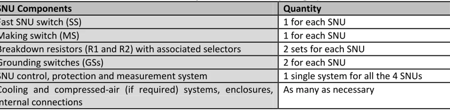
The technical specifications of this Call for Tender regard the design, manufacturing, factory testing, packaging, transportation to the Port of Entry in Japan (PoE) [3] of the 4 SNUs of the CSs of the new JT-60SA tokamak. These 4 coils are classified as CS1, CS2, CS3 and CS4. The SNU main components included in the present Procurement are listed in Table 1.
The activities at Naka Site, as installation and assembly on site, commissioning and Site Acceptance Tests, are not included in the present Procurement. Nevertheless, they are described in this document and in the references to help the IS in developing the design and the documentation. The IS shall provide a self-consistent documentation containing any information necessary to complete the installation in good conditions and respecting the time schedule.
In addition to the main components of Table 1, the Supply shall also include the following items:
The draft and the detailed design of the components object of the Supply.
A basic set of spare parts.
The tests at the IS’s facilities.
The packaging of the Supply.
The delivery of all the components to the PoE in Japan. JAEA will be responsible for transportation from the PoE to Naka Site, including formalities and temporary storage.
Any special tool and equipment necessary for the operation and maintenance of the equipment included in the Supply (these items shall remain property of JAEA).
The documentation described in the following.
The training of the operating staff.
Everything that is not unequivocally included in the technical specifications is excluded. In particular, the SNU interfaces with several systems of the machine (coils’ bus-bars, protection and control systems, cooling system, compressed air, buildings, low voltage auxiliaries power supplies, grounding grid, etc.) are not included in the Procurement.
Table 1: Main components of the SNUs (see Fig. 5).
SNU Components Quantity
Fast SNU switch (SS) 1 for each SNU
Making switch (MS) 1 for each SNU
Breakdown resistors (R1 and R2) with associated selectors 2 sets for each SNU
Grounding switches (GSs) 2 for each SNU
SNU control, protection and measurement system 1 single system for all the 4 SNUs Cooling and compressed-air (if required) systems, enclosures,
internal connections
As many as necessary
Warranty
All the components shall have a warranty for defects in the manufacture for a period of two years starting from the acceptance of the components. The warranty is limited to the direct costs of repair or remanufacturing of the components. Any other warranty is excluded.
Some extensions could be requested by the Customer.
Functional description of the JT-60SA power supply system
This section provides a short description of the JT-60SA power supply (PS) systems in order to introduce and identify the SNU functions and features. Such PS systems are widely addressed in the Section 2.7 of the PID [2]. The PID might be updated during the Contract period. The Customer shall inform the IS about PID changes relevant for this Procurement and an agreement between the Customer and the IS shall be taken on how to cope with these changes.
The JT-60SA PS system mainly consists of:
1. The PSs for the superconducting coils;
2. The PSs for the Fast Plasma Position Control (FPPC) normal conductor coils;
3. The PSs for the additional heating systems, as the positive (P-NBI) and negative (N-NBI) neutral beam injectors and the Electron Cyclotron RF (ECRF) system.
As a common understanding for design of the magnet power supplies of 60SA, the presently available JT-60U equipment shall be reused as much as possible.
Fig. 1 shows a schematic diagram of the AC PS system for JT-60SA at Naka Fusion Institute (Japan). The figure corresponds with Fig. 2.7-1 of the PID [2].
The new PS systems will be designed and manufactured to feed the superconducting toroidal field (TF) and poloidal field (PF) coils.
The ECRF system (41 MW for 100 s plasma heating) will be connected to the 275 kV commercial power grid. The P-NBI (60 MW power demand), N-NBI (40 MW power demand) and PF coil PSs will be connected to two existing motor generators (215 MVA / 4.0 GJ, 400 MVA / 2.6 GJ).
Fig. 1: Schematic diagram of the AC PS for JT-60SA [2].
The PF coil PS shall provide a bipolar DC current adequate to achieve the required scenarios. The existing JT-60 TF transformers will be re-used for 8 of the CS and equilibrium field (EF) PSs as they result compatible with the scenarios. The basic circuit components are a Base PS, a Booster PS and a SNU.
It is planned to re-use the existing vertical field coil PS (PSV) as a Booster PS.
The SNU is added into each CS PS and into the EF3 and EF4 PS to produce the high voltage necessary for the plasma breakdown and plasma current ramp-up. In principle, the SNU consists of DC current interrupters and tunable resistors, as described in the following.
Fig. 2 shows the schematics of the DC circuits for the CS1-4 PSs. As shown in the schemes, the Base PS includes the power transformers, the thyristor converters and the crow-bar switch.
The current reversing links (CRLs) are inserted in the CS and EF coil PSs to allow plasma operations with a reversal in the polarity of the toroidal magnetic field.
In case of a quench of a superconducting coil or of a failure in the PS, the magnetic energy stored in the coil must be rapidly extracted in order to protect the conductor and to shut down the plasma operation.
For this purpose, a quench protection circuit (QPC) consisting of a DC current interrupter, a dump resistor and a Pyrobreaker for back-up protection has to be provided for each superconducting coil. The SNU (and the Booster) shall be by-passed in case of operation of the related QPC to avoid overvoltages on the coil [2]. The QPC is not included in this Procurement.
Table 2 shows the basic specifications of the Base PSs, Booster PSs and SNUs for the CS 1-4 and EF 1-6 coil PSs, as reported in Table 2.7-6 of the PID [2].
Fig. 3 sketches a time diagram of CS current in which the different phases of the coil current are emphasized. The numerical values and the current diagram are reported in the figure only to clarify the SNU operational sequence. Generally, the current scenarios of a tokamak have a first phase (see Fig. 3) where the current ramps up (supplied by the Base PS) until a maximum value. Once this maximum value is reached, a sudden decrease of the current is triggered by inserting a resistor or a Booster PS in order to produce the plasma current breakdown. Fig. 3 also shows a zoom of the breakdown phase: in the JT-60SA CS1-4 and EF3-4, the sharp current variation required at the breakdown shall be realized by SNUs.
The SNU is purposely designed to insert a suitable resistor in series with the coil circuits, just immediately before the plasma breakdown. The sharp change in the coil current derivative induces a voltage in the plasma that triggers its ramp-up.
After the plasma start, there is a second phase of the scenario in which the SNU resistance generally needs to be changed in order to follow the scenario current reference. When the plasma current exceeds a prefixed value, the SNU short-circuits the resistor(s) to exclude it from the power circuit.
CS1 Circuit Configuration CS2 Circuit Configuration
+
T3G 30.1MVA×2units 18kV/803.5V %Z: 23.12% at 77.6HzSwitching Network Unit
~ -5kV CrowBar Switch
Quench Protection Circuit (Hybrid type) ±3.8kV/±20kA Superconducting Coil Base PS 939V/±10kA×2units O/C R1 R2 0.19 Current Reversing Link
+
Switching Network Unit~ -5kV CrowBar Switch
Quench Protection Circuit (Hybrid type) ±3.8kV/±20kA Superconducting Coil Base PS 1.25kV/±10kA×2units R1 R2 Current Reversing Link T-CS2 TBD MVA(New)×1unit 18kV/960V %Z: ~ 24% at 77.6Hz 0° -30° BPS C C C BPS O/C C C C 0° +30° 1 k 0.19 1 k CS3 Circuit Configuration
+
Switching Network Unit~ -5kV CrowBar Switch
Quench Protection Circuit (Hybrid type) ±3.8kV/±20kA Superconducting Coil Base PS 1.25kV/±10kA×2units Current Reversing Link CS4 Circuit Configuration
+
T4G 30.1MVA×2units 18kV/803.5V %Z: 23.12% at 77.6HzSwitching Network Unit
~ -5kV CrowBar Switch
Quench Protection Circuit (Hybrid type) ±3.8kV/±20kA Superconducting Coil Base PS 939V/±10kA×2units Current Reversing Link T-CS3 TBD MVA(New)×1unit 18kV/960V %Z: ~ 24% at 77.6Hz 0.19 0.19 +15° -15° BPS O/C R1 R2 C O/C R1 R2 C BPS MS MS C C C C +30° 0° 1 k 1 k
Table 2: Specifications for Base/Booster PSs and SNUs for CS1-4 and EF1-6 [2]. BASE PS (1)(2)(3)(8)
(duty cycle: 220s/1800s)
BOOSTER PS(5) (short time rating) SNU (kV)
Repetition time 1800s (7) (9) Forward Reverse XFMR U10 rms=18kV Vdc0 (kV) Idc (kA) XFMR U10 rms=18kV Vdc0 (kV) Idc (kA) XFMR U10 rms=18kV Vdc0 (kV) Idc (kA) U20rms (kV) Z% (4) U20rms (kV) Z% (4) U20rms (kV) Z% (4) CS1 0.8(6) 23 1.0 ± 2*10 -5.0 CS2 0.96 24 1.25 ± 2*10 -5.0 CS3 0.96 24 1.25 ± 2*10 -5.0 CS4 0.8(6) 23 1.0 ± 2*10 -5.0 EF1 0.8(6) 23 1.0 ± 1*10 2.9 + 2.9 24 7.8 +4 3.16 + 2.1 24 7.1 -14.5 0.8(6) 23 1.0 -1*10 EF2 0.72 (6) 18 0.97 ± 2*5 2.9 + 2.9 24 7.8 +4 3.16 + 2.1 24 7.1 -14.5 0.72(6) 18 0.97 -2*5 EF3 0.72(6) 18 0.97 ± 4*5 -5.0 EF4 0.72(6) 18 0.97 ± 4*5 -5.0 EF5 0.72 (6) 18 0.97 ± 2*5 2.9 + 2.9 24 7.8 +4 3.16 + 2.1 24 7.1 -14.5 0.72(6) 18 0.97 -2*5 EF6 0.8 (6) 23 1.0 ± 1*10 2.9 + 2.9 24 7.8 +4 3.16 + 2.1 24 7.1 -14.5 0.8(6) 23 1.0 -1*10 NOTE :
(1) Back-to-back four quadrants (with circulation current), 12 pulses (6 pulses during circulation current operation), demineralised water cooled converters including crow-bar unit. For each 12-pulses converter the following demi-water cooling main characteristics are needed (to be confirmed):
Q = 24 m3 /h Tin ≤ 35 °C ΔTin,out = 10 °C Pin= 450 kPa ΔPin,out = 250 kPa ρ ≥ 1 MΩ*cm
(2) Insulating voltage to ground : UM= 9 kV (ref. IEC 146-1-1 sections 4.2.1.3 and 4.2.1.4, where factory test voltage is defined as Vtest=4+1,8UM/1,41 and UM is defined as “ highest crest voltage”.)
(3) DC current accuracy (%) = ±1% of nominal value
(4) Tentative values referred to XFMR power at secondary side, at 77.6Hz (5) Two quadrants converters
(6) Already existing XFMR
(7) Reference highest voltage for equipment (IEC 60071) = 7.2 kVrms
(8) Reverse-side converters for EF1, EF2, EF5, and EF6 have two quadrants (with circulation current).
(9) For each SNU unit a cooling water flow Q = 6 m3/h is requested. In principle raw water is acceptable, if available otherwise demineralised water should be provided.
Time C o il an d S N U c u rr en t Slope due to R1 Slope due to R1//R2 Ramp-up Breakdown zoom Breakdown Ramp-down Current reversal
(limit for SNU operations)
≤250 s ≤20 kA
SNU bypassed
Fig. 3: Example of CS current scenario with a zoom of the breakdown phase to emphasize the effect of the SNU operations.
Other coil power supplies (only for information)
The EF coil PSs are basically based on the same principles presented for the CS PSs.
The circuit for the TF coil PS is shown in Fig. 4, corresponding with Fig. 2.7-2 of the PID [2]. The 11 kV network provides the AC source voltage of the TF coil PS.
The TF coil PS shall be able to provide the required 25.7 kA DC current continuously to the superconducting TF coils. The nominal DC voltage shall be sufficient to charge or discharge the full current within about 20 minutes. Typical operation of the TF coil PS is that the TF coils are energized every day in the morning before the starting of the plasma experiments and demagnetized after the experimental period.
The set of the JT-60SA PSs is completed by the PSs for upper/lower FPPC coils, for Resistive Wall Mode (RWM) suppression and for error field correction.
TF1-TF6 TF7-TF12 TF13-TF18 QPC1 QPC2 QPC3 Thyristor Converter ~ ±80V / +25.7kA Crowbar Switch
Current Reversing Link
Current Reversing Link
Current Reversing Link BPS C C BPS BPS 2.2MVA 11kV/60V %X: TBC 1 k < 0.055 < 0.055 160 160 160 < 0.055 < 0.055 < 0.055 < 0.055
SNU specifications and requirements
The IS must develop his technical proposal in accordance with the functional specifications included in the present document.
The final solution proposed by the IS shall be agreed with the Customer during the Detailed Design Phase (DDP). In any case, the IS shall take upon himself the comprehensive liability on the conformity of the technical proposal to the specifications and to the other documents and references related to the Procurement.
SNU basic scope
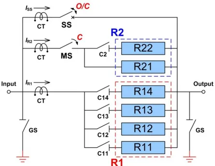
The SNU functional scheme is displayed in Fig. 5 (see Fig. 2.7-11 of the PID [2]). The SS has to close and open while the load current is flowing, in order to insert the resistance R1 in the coil circuit. The MS has to insert, during the shot, the resistance R2 that will be in parallel with R1.
The values of the resistance R1 and R2 change according to the resistors pre-inserted in the circuit. The values of the two sets of resistors R1 and R2 are arranged, before the start of the pulse, by the selectors C2, C11, C12, C13 and C14 shown in Fig. 5.
The resistors required for each SNU are shown in Table 3.
Since the voltage drops caused by R1 and R2 are directly proportional to the current amplitudes, different scenarios can be realized by modifying the resistances values. During a single shot it is possible to insert a resistance value for each resistor set R1 and R2, pre-arranged by an opportune combination of the values shown in the Table 3.
Fig. 3 shows a typical current diagram in a tokamak coil with the only purpose to clarify the SNU operational sequence. This sequence is summarized in the following:
1. In the ramp-up phase the Base PS, based on thyristor converters (see Fig. 2), increases the coil current up to a maximum positive value (20 kA). In this phase, the SS is closed and the MS is opened (see Fig. 5).
2. At the breakdown, the SS switches off. Consequently, the current changes over the resistor set R1 and its derivative changes immediately.
3. After some tens of milliseconds, if a smaller current derivative is needed, the MS inserts the resistor set R2 in the coil circuit. The timing accuracies of the SS and MS are particularly critical because strictly related to the plasma start-up.
4. After this phase, and in any case before the possible current reversal, the resistors will be disconnected from the power circuit closing again the SS (the MS can be opened at zero current flowing in its branch).
5. The state of the SNU does not change during the rest of the scenario. The entire scenario can last up to 250 s.
The switching commands for the SS and the MS come from the JT-60SA control systems. As their timing depends on the current scenario around the breakdown, the SNU Local Control Cubicle (LCC) shall check, also, the right sequence (interlocks) of the switching commands (SS opening → MS closing → SS closing). The SS shall be sized for the nominal current (20 kA) and for the maximum pulse length (250 s). The data in Table 3 fixes also the characteristics of the switches related to the resistors. In particular, since the resistance R2 is inserted by the MS, the MS shall be sized considering the dump energies of the resistors R21 and R22.
The maximum operational voltage and the reference highest voltage for equipment (IEC 60071) are identical for all the resistors and correspond to the maximum values possible in the SNU (see Table 4). The specifications of the SNU components and systems and their operation mode are described in the following sections.
Fig. 5: Functional scheme of the SNU. Table 3: Characteristics of the SNU resistors.
Item Resistance Rated Current Dump Energy Max voltage Voltage (IEC 60071)
R1 R14 3.75 Ω 1.333 kA 2 MJ 5 kV DC 7.2 kV rms R13 1.875 Ω 2.667 kA 4 MJ 5 kV DC 7.2 kV rms R12 0.9375 Ω 5.333 kA 8 MJ 5 kV DC 7.2 kV rms R11 0.4688 Ω 10.667 kA 16 MJ 5 kV DC 7.2 kV rms R2 R21 0.05 Ω 10.0 kA CS1, CS4 CS2, CS3 5 kV DC 7.2 kV rms 30 MJ 20 MJ R22 0.05 Ω 10.0 kA CS1, CS4 CS2, CS3 5 kV DC 7.2 kV rms 30 MJ 20 MJ Table 4: Main parameters of the SNU.
SNU Parameter Value
Nominal current ±20 kA
SS maximum conducting current ±23 kA
SS maximum interrupting current 20 kA
Maximum pulse length 250 s
Minimum repetition time 1800 s
Current interruption Unidirectional
Rated voltage 5 kV
Maximum transient voltage 7 kV
Reference highest voltage for equipment (IEC 60071) 7.2 kV rms
SS and MS maximum switch-on/off time ≤1 ms
SS operation accuracy/repeatability ≤0.5 ms
MS operation accuracy/repeatability ≤1 ms
SNUs installation Indoor
Indoor maximum to minimum temperature 40/5 °C
Maximum monthly average relative humidity 87%
Accuracy of each breakdown resistor (at 20°C) ±2%
Maximum variation of resistors with temperature ±10%
SNU functional parameters and operating mode
Table 4 summarizes the main parameters on which the SNU design shall be based, as explained in the following.
The nominal current reported in the table refers to the expected standard operational conditions. In addition, it is necessary to consider that a plasma disruption can induce in the coil current a step increasing of about 2.6 kA.
The repetition time is the time interval between two following experimental pulses (see Table 1.2-1 of the PID [2]). A pulse can last a maximum of 250 s including a maximum initial ramp-up time of 40 s. The JT-60SA working time for the experiments shall be 10 hours per day.
The operations shall be performed except in the case of dew condensation. JAEA will stop the operations in case of risk of dew condensation.
The scenarios included in the PID [2] could be changed during the project. In case of changes, the possible consequent modifications in the SNUs shall be agreed between the Customer and the IS.
All the PF coil PSs are 4-quadrants type, so both the voltage and the current can reverse. As the SNUs operate in a fixed phase of the scenario in which the current direction does not change, the current can be considered unidirectional to the SNU aim. If the inversion of the coil currents is needed, it could be realized by the CRL polarity changers (see Fig. 2). In any case, the SS shall be re-closed before the reversing of the load current.
The rated voltage between the SNU terminals at the breakdown is 5 kV. This voltage shall not overcome 7 kV in any case, including all the possible contributions (transients, commutations, resistance tolerances and temperature variations). As a consequence, in compliance with the Standard IEC 60071, the insulation level of the device should be 7.2 kV rms. In fact, according to the Table 2 in Standard IEC 60071-2, the corresponding standard rated short-duration withstand voltage is 20 kV rms. The value of the maximum transient voltage may be revised during the DDP according to new information provided by JAEA.
The SS operation controls the plasma start-up, so it must be very fast and accurate. In particular, the SS has to switch-off (namely, its current decreases under the 2% of its initial value) in less than 1 ms after the activation of the related command and the accuracy of the timing of the operation must be better or equal to 500 μs. Therefore, in the worst-case the SS switch-off time can be 1.5 ms. The same requirements will be assumed for the SS turn on.
If the SS turn on and off commands consist in a sequence of commands, the value for the “Maximum switch on/off time” in Table 4 refers to the final command that inserts or removes the resistors in/from the coil circuit.
The SS shall operate with the time performances reported in Table 4 in the whole operational current range.
The MS switch-on time can be identical to the SS one (1 ms), while the accuracy can be up to 1 ms (worst-case switch-on time 2 ms).
Control strategy
The JT-60SA Supervisory Control System and Data Acquisition System (SCSDAS) is described in Section 2.17 of the PID [2]. The JT-60SA control system will also include a system for handling the protection signals received from the equipment and distribute the protection commands (GPS) and a system for managing the safety interlock signals (SIS). The detailed design of such systems is yet under development.
The JT-60SA PS system will be directly managed by a dedicated Power Supply Supervising Computer (PS SC), provided by JAEA, that communicates with SCSDAS, GPS and SIS. The PS SC includes an Internal Protection System (IPS) that coordinates protective actions among all JT-60SA PS components and among them and the remaining parts of the JT-60SA system.
Fig. 6: General diagram of the protection signals of the JT-60SA PS system [11].
The SNU Procurement includes a dedicated LCC with functions of control, backup, protection, interface and information. The LCC hardware essentially consists of a central unit based on PLC or industrial PC devices and of a set of interfaces towards the SNUs and the human-machine interface (HMI). The HMI hardware shall contain an LCD screen with touch commands or keyboard to display and control friendly high-level panels, possibly including graphic mimics of the devices.
The SNU LCC is connected to the PS SC that can communicate with the rest of the JT-60SA plant, as sketched in Fig. 6 that coincides with Fig. 3.2 of [11]: “H” is a protection signal used by the SNU LCC to inform the IPS that an internal fault, requesting an action, occurred in one SNU, “J” is a protection command used by the IPS to prevent the operation of all the SNUs [11].
Each SNU can operate either in local control mode (LCM) or in remote control mode (RCM), depending on the state of a key selector placed on each SNU. The HMI monitors the plant status and measurements in both modes. The safety signals are independent of the selected mode. Each SNU shall have a panel signaling the LCM/RCM and on/off operations, just as the interlock devices (alarm push button, safety interlocks).
Fig. 7: RM loops for JT-60SA power supply control system [7].
In the LCM case, the HMI provides an easy management of all the input/output actions (commands, sequences, status monitoring, measurements, and so on) necessary for effective SNU commissioning, testing and troubleshooting. Also in LCM, the LCC transmits the signals from the SNU to the PS SC.
When the RCM is activated, the SNU will be under the control of the PS SC. In this case, the switching commands will come directly from the PS SC and the LCC will transfer them, after checking all the necessary conditions, to the implementing device with the time constrains summarized in Table 4.
In general, the signals can be classified according to the type of connection as: 1. Signals transmitted through the Reflective Memory (RM);
2. Signals transmitted through optical links (single signals or encoded signals); 3. Hardwired protection commands;
4. Ethernet-based links for process control and trouble-shooting.
Moreover, from the point of view of their updating rate, the signals can be classified as:
1. Slow signals, intended for system configuration, monitoring (including status and alarm visualization), slow measurements and safety interlock signals (typically managed by the SIS); 2. Fast signals, intended for purposes of timing, data acquisition and real time control (typically
managed by the GPS).
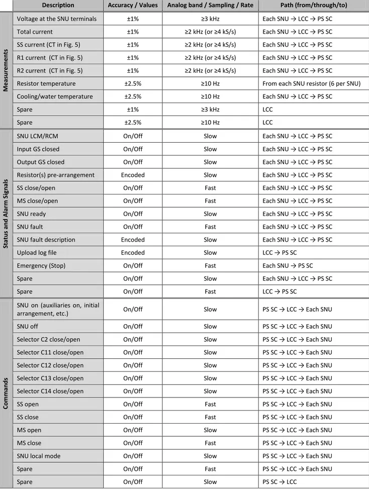
The IS shall provide the RM units, produced by General Electric (see [7]), for the communications (alarms, states, commands and measurements) with the control systems. The architecture of the RM loops for the power supply control system is sketched in Fig. 7 that coincides with Fig. 1 of [7]. The IS shall also provide Ethernet access to its CPUs/controllers by using only standard ways of communications and software interfaces.
Table 5: List of signals transferred to/from LCC from/to PS SC.
Description Accuracy / Values Analog band / Sampling / Rate Path (from/through/to)
M e asu re me n ts
Voltage at the SNU terminals ±1% ≥3 kHz Each SNU → LCC → PS SC Total current ±1% ≥2 kHz (or ≥4 kS/s) Each SNU → LCC → PS SC SS current (CT in Fig. 5) ±1% ≥2 kHz (or ≥4 kS/s) Each SNU → LCC → PS SC R1 current (CT in Fig. 5) ±1% ≥2 kHz (or ≥4 kS/s) Each SNU → LCC → PS SC R2 current (CT in Fig. 5) ±1% ≥2 kHz (or ≥4 kS/s) Each SNU → LCC → PS SC
Resistor temperature ±2.5% ≥10 Hz From each SNU resistor (6 per SNU) Cooling/water temperature ±2.5% ≥10 Hz Each SNU → LCC → PS SC
Spare ±1% ≥3 kHz LCC Spare ±2.5% ≥10 Hz LCC Statu s an d A lar m S ig n al s
SNU LCM/RCM On/Off Slow Each SNU → LCC → PS SC
Input GS closed On/Off Slow Each SNU → LCC → PS SC
Output GS closed On/Off Slow Each SNU → LCC → PS SC
Resistor(s) pre-arrangement Encoded Slow Each SNU → LCC → PS SC
SS close/open On/Off Fast Each SNU → LCC → PS SC
MS close/open On/Off Fast Each SNU → LCC → PS SC
SNU ready On/Off Slow Each SNU → LCC → PS SC
SNU fault On/Off Fast Each SNU → LCC → PS SC
SNU fault description Encoded Slow Each SNU → LCC → PS SC
Upload log file Encoded Slow LCC → PS SC
Emergency (Stop) On/Off Fast Each SNU → PS SC
Spare On/Off Slow Each SNU → LCC → PS SC
Spare On/Off Fast LCC → PS SC
C
o
mman
d
s
SNU on (auxiliaries on, initial
arrangement, etc.) On/Off Slow PS SC → LCC → Each SNU
SNU off On/Off Slow PS SC → LCC → Each SNU
Selector C2 close/open On/Off Slow PS SC → LCC → Each SNU Selector C11 close/open On/Off Slow PS SC → LCC → Each SNU Selector C12 close/open On/Off Slow PS SC → LCC → Each SNU Selector C13 close/open On/Off Slow PS SC → LCC → Each SNU Selector C14 close/open On/Off Slow PS SC → LCC → Each SNU
SS open On/Off Fast PS SC → LCC → Each SNU
SS close On/Off Fast PS SC → LCC → Each SNU
MS open On/Off Slow PS SC → LCC → Each SNU
MS close On/Off Fast PS SC → LCC → Each SNU
SNU local mode On/Off Slow PS SC → LCC → Each SNU
Spare On/Off Fast PS SC → LCC → Each SNU
The IS has to evaluate if the management of the fast signals and of the sequence need a specific hardware (e.g. FPGA), while the slow signals can be usually handled by PLCs or industrial PCs.
Table 5 reports a tentative list of the signals between each SNU, the LCC and the control systems. A more detailed list of the status, command, alarm, measurement signals to be exchanged in JT-60SA is provided in [6]. The final list with the related features shall be fixed during the DDP. In any case, the signals to be transmitted from the components of each SNU to the LCC shall comply with what reported in Table 5 with the addition of any other signal needed for an effective and safe control of the SNU itself.
The IS shall provide all the measurements (voltage, current, temperature, water/air flow, etc.) necessary to control and protect the system, including proper adjustable thresholds. The signals defined as “spare” in Table 5 will be defined in the DDP or will be available for later modifications/integrations. Each measurement is compared with, at least, a threshold, whose trip will converge on overall signals as “SNU fault” and “SNU ready”. For some measurements (e.g. temperatures), a “warning” threshold can be necessary, too.
The measurement accuracy required in Table 5 must be evaluated considering the total measuring chain from the probe to the interface with the PS SC. The percentage is referred to the measurement full scale. The analog measurement band is the signal maximum useful frequency, corresponding to the cut-off frequency at -3 dB. This specification is alternatively based on the sampling frequency as it is done in the datasheets of some transducers. The measurement performances listed in Table 5 are only a reference for global quantities: higher accuracy, bandwidth, sampling time could be necessary to verify and control the operations of the critical elements in the selected scheme.
All the alarms from/to the SNU, the LCC and the PS SC will be of fail-safe type. This means that the absence of the signal (light, voltage, current) must be considered as an alarm’s presence.
The LCC shall elaborate, display and save a log file in which all the changes in the SNUs’ conditions and states are recorded with the corresponding time.
Both in LCM and in RCM, the LCC shall be able to pre-arrange the resistor sets by the C2, C11, C12, C13, C14 selectors (see Fig. 5) according to the desired pulse characteristics.
In every condition, the LCC has to check the right working of the SNU components and systems and carry out all the procedures, of fail-safe type, to protect them. They shall be defined in the DDP according to proposals made by the IS [11].
The subject of the human safety regarding the activities on the SNUs shall be carefully analyzed by the IS. The human safety must rely on fail-safe and hardware components (mechanical interlocks, grounding connections and switches, circuit breakers, screens, etc.). During the DDP, all the information necessary to design the system in compliance with the safety rules will be given. Detailed information on the JT-60SA safety rules can be found in [8].
SNU cooling system
The SNUs will be cooled by the cooling water plants of Naka Site. The inner cooling plants of the SNU are included in this Procurement. The IS should terminate the internal cooling plants with proper flanges. The connections from these flanges to the Naka Site cooling water plants are not included in the Procurement. The mechanical interfaces for such connections shall be defined during the DDP.
The SNU will be installed at the second floor of the Rectifier building. In this room, a demineralized water cooling system for aluminum components and a raw water cooling system (JT-60SA Secondary Cooling System) are available.
The available flow rate of raw water for the SNU (breakdown resistors) cooling is 6 m3/h (see Table 2 taken from 2.7-6 of the PID [2] and the water cooling diagram in Fig. 2.7-12 of the PID [2]).
If the exhaust air temperature exceeds 100 °C, the SNU heat losses (as from the breakdown resistors) cannot be directly dissipated into the installation room and must be transferred to the raw water.
If the SNU heat losses are dissipated in the room air, the IS shall provide a report analyzing the variation of the room air temperature, in order to assure that such temperature never exceeds 50 °C due to the SNU operations.
The IS shall assess if the demineralized water cooling is necessary for the SNU static switches (mainly considering the results of his fault analysis). This option shall be agreed with the Customer during the DDP.
The sizing, layout and cooling of every power component should be analyzed in order to fulfill, with adequate safety factors, its temperature limits. The IS, considering also the dump energies of Table 3 and resistors specifications of Table 4, shall design the cooling system to ensure that the temperatures of the SNU components go back to the initial values within 30 minutes.
The available measurement systems shall monitor the hottest points of the SNU, identified during the DDP and modified, if needed, after the testing phase. The temperature measures coming from the SNU should be collected and elaborated by the LCC that controls the cooling system and provides summarized information to the PS SC.
The water circulation in the SNU shall be checked by flow switches. Insulating valves shall be installed at the interface points with the Site plant and anywhere needed to facilitate the maintenance procedures. Furthermore, proper automatic air bleed valves, filters and drain valves shall be fitted up.
Layout and installation requirements
The installation is not included in the present Procurement, but some related information is reported in following.
Before the start of the installation phase, JAEA will make available all the areas where the SNUs will be installed and the services described in [8] and [9].
During the assembly and installation activities, all the requirements and rules reported in [8] and [10] shall be applied and followed.
If needed, additional layout drawings of the relevant JT-60SA buildings will be provided by the Customer during the DDP. Possible revisions necessary during the development of the design will be agreed as applicable.
The design of the SNU system shall be compatible with the JT-60SA layout and with the provided information.
The SNUs shall be installed where indicated in the drawings in the following. The SNU size shall be consistent with the available dedicated area and access gates showed in the drawings. The 4 SNUs shall be installed in the Rectifier Room of the Rectifier Building. These drawings include the areas available for the SNUs (diagonal broken lines) and some possible space allocations (rectangles SS, MS, R, S1). The space allocations suggested by the rectangles SS, MS, R, S1 are only indicative.
The average load to the floor shall be less than 700 kg/m2 for Rectifier Room (see Fig. 16). This value will be confirmed during the DDP. The basement geometry of the devices shall be agreed with the Customer during the DDP.
No crane is available in the areas where the SNU will be installed.
An overall description of the JT-60SA Site and buildings is reported in Section 2.22 of the PID [2].
Enclosures
All the live parts of the SNU shall be housed in cubicles and cabinets to avoid the access to hazardous parts. The enclosures must comply with the Standard IEC 60529. The protection degree of the cabinets containing the switches and the resistors must be at least IP 52DH. The IP codes could be reviewed and agreed with the Customer during the DDP. Open frames can be accepted, except for the breakdown resistors, by properly enclosing with fences or equivalent structures. The IS shall justify the selection of a particular enclosure, including the use of open frames, also considering the consequences on the electromagnetic compatibility of the SNUs and related systems.
The signals terminal blocks and the command/control boards should be separated, by a protection shield, from the hazardous parts.
The SNU internal circuits shall be protected by proper main circuit breakers. Additional circuit breakers must be inserted to separate and effectively protect different subsets of equipment according to their location or functionality. Each circuit breaker shall interrupt all the AC phases and the neutral or both the DC polarities (±VDC).
A 200 V AC mains plug shall be fitted inside each cabinet and shall be protected by a differential circuit breaker (16 A, 300 mA). All the circuit breakers shall be in accordance with the IEC standards.
The cubicles shall be fitted with low-consumption lamps for internal lighting, turned on by the opening of the doors.
Dimensions of any panel, box and cabinet shall contain a minimum of 20% of spare area (for panels) or volume (for boxes and cabinets). The wiring channels shall contain a minimum of 20% of spare space. The wiring channels shall be halogen-free and flame retardant, fitted with a cover and secured by screws. The doors shall be provided with locks. In any case, the internal parts of the SNU will be accessible only in compliance with the safety procedures.
The thickness of the steel of the cabinets will be at least 1.5 mm. The plates will be passivated and painted by epoxy polyester powder coating. The color code will be given in the DDP.
The mechanical cabinets must be connected to the ground grid of the Site. All its metallic parts (frame, doors, panels, etc) will be linked to the ground bolt. The grounding circuits should be designed for a single short-circuit withstand and consistent with the Standards IEC 60204-11 and IEC 62271-200. All the ground connections shall be easily spotted. JAEA will connect the ground terminal of the SNU system to the closest terminal of the grounding network of the building.
Adequate test points, with easy access, shall be included in the equipment to allow quick maintenance and troubleshooting. The test points will be defined during the DDP according to a proposal from the IS.
Each cubicle must be properly cooled/heated, also taking into account the site conditions, to ensure that all the internal components can properly operate and that no damage occurs to them.
The IS should provide all the documents certifying the conformity of the equipments to the IEC standards and the shielding code (EM) according to the Standard IEC 61000-5-7 of the electronic cards enclosures.
Interfaces
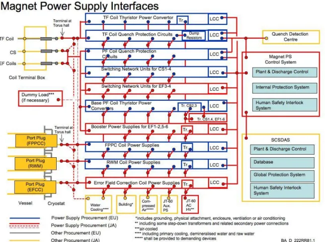
The JT-60SA interfaces are widely presented in the PID [2]. The IS shall particularly take care of all the information concerning the integration of the SNUs in JT-60SA (see in particular Section 4 of PID [2]). Fig. 8, coincident with Figure 2.7-6 in the PID [2], shows the interfaces of each unit of the coil PSs with respect to the rest of JT-60SA systems. In the scheme, the interfaces are represented with circles. The colors of the interfaces indicate the respective procurement. The color of the line connecting two interfaces indicates the organization providing the physical connection between the interface points.
Fig. 9 is focused on the SNU interfaces. The external dashed rectangle stands for the boundaries between the EU (in practice, this Procurement) and the JAEA procurements. The blue dots represent the interfaces among the SNU and other systems. The final connections are part of the JAEA task. The numerical values reported in the boxes are only preliminary. The IS shall assess if these values are adequate and if additional plants/systems are needed.
LCC SS Resistors MS SS Resistors MS SS Resistors MS SS Resistors MS DC feeders Grounding grid Raw water 6 m3 /h x 4 CS1 CS2 CS3 CS4 Compressed air 400 Vac EG 5 kVA x 4 400 Vac UPS 1.5 kVA x 4 400 Vac 10 kVA x 4
Building I/O signals
to/from PS SC
I/O signals to/from IPS
DC feeders DC feeders DC feeders
JA responsibility
EU responsibility Connection on the EU apparatus
Fig. 9: Summary of SNU interfaces and corresponding responsibilities.
Interface with the DC power and the coil
The two power terminals of each SNU will be mechanically connected to the corresponding converter and coil through DC bus-bar/cables not included in the present procurement. For this purpose, the IS shall provide aluminum connection terminals, including flexible links, with suitable cross-sections.
In considerations of galvanic corrosion and heat generation, the surface of the terminals, which are directly contacted with DC feeders (via flexible conductors), shall be treated by finishing and cleaning for the case of copper, or silver plating after copper plating for the case of aluminum.
The final design related to terminals and links, including final position and mechanical details, shall be agreed with the Customer during the DDP.
Interface with the low voltage distribution system
JAEA will provide for the four CS SNUs the auxiliary electrical supplies reported in Table 6. The IS shall verify these data with respect to his requirements.
The JAEA 400 V AC normal and emergency (Emergency Generator and UPS) networks will supply the control and auxiliary plants of the SNU system.
The Emergency Generator is activated in case of failure in the normal power network. Since the generator takes few tens of seconds to start up, the power to the loads is interrupted during this time.
The IS shall design, and agree with the Customer during the DDP, the low voltage internal distribution system to be provided.
The interface between the SNU and the JAEA AC systems consists in the connections of the supply cables to the SNU terminal blocks. The IS shall install the terminal blocks of the low voltage cables in the SNU cabinets.
JAEA will provide the low voltage distribution board including the circuit breakers and the low voltage supply cables. Moreover, JAEA will lay down the low-voltage supply cables to the SNU and will terminate them at the SNU cubicles.
Table 6: Auxiliary voltages for the four CS SNUs.
Type Network Emergency Generator UPS
Nominal voltage 400 V AC 400 V AC 400 V AC
Phases and wires 3ph 4w 3ph 4w 3ph 4w
Voltage variations ±10% ±10% ±5%
Nominal frequency 50±0.1% Hz 50±5% Hz 50±0.1% Hz
Total harmonic distortion – – <5%
Maximum available power 40 kVA 20 kVA 6 kVA
Interfaces with the fluids systems
An industrial standard compressed air plant is available in the installation area. If needed, the IS shall identify the features of the compressed air facilities.
The internal distribution system of the compressed air is a task of the IS. The IS shall connect his apparatus to the JAEA compressed air distribution system, adapt it to the specific needs of the apparatus (valves, measurements, filtering, lubrication, drying, pressure value, and so on) and distribute it among all devices where necessary.
Enough compressed air shall be stored in the procured apparatus to operate a full cycle (open-close-open) of all the switches. The pressure level of the stored compressed air shall be monitored and controlled, also by including suitable status/alarm signals.
JAEA provides the pipes close to the SNU cubicle and connect the local compressed air distribution system to the SNU pipes. The interface between the SNU and the JAEA compressed air distribution system consists in the termination of the pipes in the SNU cubicles.
Interface with the grounding grid
Each SNU, LCC and cabinet shall have a ground bolt. JAEA will connect one of them to the nearest grounding terminal of the grid. The IS shall realize the internal grounding connections among the SNU parts with copper conductors of adequate section, able to carry the fault current without voltage rises dangerous for the human safety.
All the power ground connections for the SNU high-voltage equipment shall be sized in compliance with the IEC standards.
Interfaces with the building
All the SNU components will be installed indoor, in the Rectifier Room of the Rectifier Building in Naka Site. The drawings show the areas available for all the SNU equipment. No extra areas will be available for the assembling.
Water cooling, compressed air and low voltage distribution plants are available in the installation room. The IS shall design the SNUs taking into account the constrains on the maximum load of the Rectifier Room floor.
Interfaces with PS SC, SCSDAS, GPS and SIS
The SNU LCC will exchange slow and fast signals with the PS SC. The interfaces for such signals should be mainly based on Ethernet and RM cards.
The general architecture, the communication principles, the exchanged signals and the RM loops are described in [6] and [7].
The exact rules for the selection of the interface type shall be agreed during the DDP. In general, only the RM-based signals should be adopted for communications necessary during the experiments, while Ethernet should be used only for diagnostic purposes.
The IS shall provide the suitable terminations for the interface to the PS SC. JAEA will provide the optical fibres to connect the PS SC to the SNU LCC and will terminate them in the LCC with complementary connectors. The IS shall select the most suitable connector type on the basis of his own experience. In case of selection of not-widely available connectors, the IS shall provide also the complementary connectors. The signals between the SNU and the IPS shall be defined with the Customer during the DDP on the basis of the IS’s proposals (see also the proposal in Table 5).
SNU reference scheme
This section presents a reference scheme for the SNU design. Obviously, the IS is free to propose another scheme that he consider more suitable to meet the technical specifications on the basis of his own experience. The final scheme shall be agreed with the Customer during the DDP. In any case, independently from the selected scheme, the IS takes upon him the full responsibility of the procured components included in the present technical specifications.
The most relevant requirements of the SNU are the time accuracy and repeatability of the SS and MS operations. In addition, these performances should be obtained minimizing the maintenance time necessary for the re-establishment of the switch contacts.
Especially for these reasons, the proposed reference design is based on the “hybrid scheme” sketched in Fig. 10. The name of “hybrid circuit” is due to the fact that the SS is implemented by two systems in parallel: the former is based on a electromechanical by-pass switch (BPS), the latter on a static circuit breaker (SCB), implemented by Integrated Gate-Commutated Thyristors (IGCTs). The SCB must meet the requested switch-on/off times supporting the BPS in diverting the current to the resistance R1.
Slope due to R1 Slope due to R1//R2 BPS command SCB command MS command Coil current
Fig. 11: Example of switching operations in the hybrid scheme. At the breakdown, the current abruptly decreases with two different slopes due to the SNU resistors R1 and R2.
This design based on the hybrid scheme has been investigated in several simulations. In particular, Fig. 10 shows a simulation model including the thyristor converter voltage source, the current reference signal, the crow-bar unit (CBU), the voltage divider (obtained by the resistors R5 and R6) with the ground connection (R4) and the coil load (Lcoil).
The resistance R3 in Fig. 10 is connected in series with the BPS to create the minimum voltage drop that ensures a full conduction in the SCB, thus reducing the opening current in the BPS. Since, of course, this resistor introduces also heat dissipation, its utility and optimal value must be evaluated by the IS.
Typical operation sequence of the reference scheme
The basic principles of the proposed SNU scheme are here described with the help of Fig. 11. The time and current values in the graphs are only examples for preliminary simulations and not necessarily consistent with a real case. The first row in Fig. 11 reports the coil current, practically coincident with its reference signal (current scenario). The other three sub-figures of Fig. 11 display the sequence of opening/closing actions of the three switches (when the signal is high the switch is closed and vice versa).
The operation sequence is summarized in the following:
1. Before the breakdown (magnetization phase) the current in the coil increases up to its nominal maximum (20 kA). In this phase, the BPS is closed, the SCB and the MS are opened. 2. Shortly before (hundreds of milliseconds) the breakdown, the SCB switch is closed, the
current diverts from the BPS to the SCB.
3. The BPS and, successively, the SCB are opened, pushing the current in the resistor R1. 4. The MS inserts the second resistance R2. This terminates the breakdown phase.
5. The cycle goes on returning to the initial conditions: the SCB and, successively, the BPS are closed, diverting the current from the resistors
6. At the end of the SNU operations, the SCB is opened and only the BPS is connected in the circuit. It is interesting to stress that in this circuit topology the current in the MS is very low and it can be easily opened.
7. After the SNU operations, the current is controlled only by the thyristor-based converter 8. If the coil current changes direction, the negative current flows only in the BPS. Anyway, the
coil current can be inverted by the CRL (see Fig. 2).
As stated in Table 5, the fast open/close commands for the switches are sent from the SCSDAS and form the PS SC to the LCC. The LCC must adapt and transform them to the commands necessary for the BPS, SCB and MS.
By-pass switch (BPS)
The BPS as proposed in the hybrid scheme is an electromechanical device that conducts the coil current before and after the breakdown phase. Therefore, the BPS shall be designed to sustain the nominal current for the whole pulse length.
The main parameters concerning the BPS are summarized in Table 7 (see also Table 4 in which only the SS is considered). The IS design shall include a description of the main characteristics of the selected device in order to verify their agreement with the technical specifications.
The value of maximum current IBPSmax reported in Table 7 takes into account that the plasma disruption can induce in the coil circuit a current step increase. Fig. 12 shows the induced current waveform exceeding the rated current in case of plasma disruption. The event exemplified in the figure affects a current in positive polarity, but the behavior can be simply extended to the case of negative polarity.
The maximum interrupting capability requested to the BPS depends on the selected operational scheme and could be reduced by the insertion of the resistance R3 in Fig. 10.
If the BPS is implemented by more parallel contacts, the current among them must be as uniform as possible. To this aim, the current unbalance factor for a parallel contact is defined as
contact average BPSmax
contact average average contact 100 I I , I I I I N , (1)
in which Icontact is the current value in the considered contact when the total current in all the Ncontact parallel contacts is at the maximum value IBPSmax. Then, the maximum ΔIcontact allowed in the contacts should be under the 20%. Such value will be verified in Factory Tests.
The opening time can be defined as the time necessary for the extinction of the current flowing in the BPS during a SNU operation equivalent to an opening of the SS (this current can be measured in the BPS branch after the BPS starts to open). In presence of arc, the opening time can be also defined as the contact opening time from the start of the arc formation to the completely opened state to ensure the required insulating performance.
In any case, the IS shall declare in his proposal the relevant characteristics and performances of the BPS and shall indicate the sequences and the conditions in which such characteristics and performances can implement the SS operations together with the SCB. This indication shall be supported by calculations and simulations (and experimental data, if available).
The BPS component selection shall be focused on the maintenance requirements: the BPS shall ensure at least 10000 mechanical open/close operations without maintenance (excluding the sacrificial contacts). The IS shall indicate the nominal number of open/close operations at nominal current before maintenance, in particular for the sacrificial contacts. This number is expected to be not less than 300.
If the switch is operated by compressed air, it shall complete at least two open/close/open cycles when disconnected from the JAEA compressed air system.
The BPS must be inserted in a mechanical enclosure. The switch on/off buttons, normally available in this kind of equipment, will be shielded by a locked door. Moreover, it will be possible to disable them in RCM.
20 kA
23 kA
2 s
1 s
0 kA
Fig. 12: Current waveform exceeding the rated current in case of plasma disruption.
Table 7: Basic technical data of the BPS (see also Table 4).
BPS Parameter Value
Nominal current ±20 kA DC
Maximum current IBPSmax ±23 kA DC
Maximum pulse length 250 s
Minimum repetition time 1800 s
Current direction Bidirectional
Rated voltage between terminals 5 kV
Highest voltage for equipment (IEC 60071) 7.2 kV rms
Opening time ≤10 ms
Operation accuracy/repeatability ≤5 ms
Number of operations without maintenance (excluding sacrificial contacts) 10000
Open/close/open cycles without compressed air ≥2
Table 8: Basic technical data of the SCB (see also Table 4).
SCB Parameter Value
Nominal current ISCBn 20 kA DC
Interrupting capability (including safety factor) 25 kA DC
Maximum current unbalance factor ΔIbranch 20%
Minimum repetition time 1800 s
Current direction Unidirectional
Maximum voltage between terminals 5 kV
Highest voltage for equipment (IEC 60071) 7.2 kV rms
Switch-on/off time ≤1 ms
Operation accuracy/repeatability ≤0.5 ms
Accuracy of current measurements 1%
![Fig. 1: Schematic diagram of the AC PS for JT-60SA [2].](https://thumb-eu.123doks.com/thumbv2/123dokorg/5604105.67870/11.892.159.736.141.476/fig-schematic-diagram-ac-ps-jt-sa.webp)
![Fig. 2: CS1-4 PS circuit configuration (see Fig. 2.7-3 of the PID [2]).](https://thumb-eu.123doks.com/thumbv2/123dokorg/5604105.67870/12.892.135.761.152.1101/fig-cs-ps-circuit-configuration-fig-pid.webp)
![Table 2: Specifications for Base/Booster PSs and SNUs for CS1-4 and EF1-6 [2]. BASE PS (1)(2)(3)(8)](https://thumb-eu.123doks.com/thumbv2/123dokorg/5604105.67870/13.892.80.820.148.751/table-specifications-base-booster-pss-snus-cs-base.webp)
![Fig. 4: Schematic of the TF coil circuit configuration [2].](https://thumb-eu.123doks.com/thumbv2/123dokorg/5604105.67870/14.892.95.801.887.1139/fig-schematic-tf-coil-circuit-configuration.webp)
![Fig. 6: General diagram of the protection signals of the JT-60SA PS system [11].](https://thumb-eu.123doks.com/thumbv2/123dokorg/5604105.67870/18.892.150.748.134.821/fig-general-diagram-protection-signals-jt-sa-ps.webp)
![Fig. 7: RM loops for JT-60SA power supply control system [7].](https://thumb-eu.123doks.com/thumbv2/123dokorg/5604105.67870/19.892.87.802.132.663/fig-rm-loops-jt-sa-power-supply-control.webp)