2017
Publication Year
2020-09-23T10:00:28Z
Acceptance in OA@INAF
Analysis of Vivaldi array antenna for phased array feeds application
Title
Liu, Lei; Grainge, Keith; Navarrini, Alessandro
Authors
10.1109/NEMO.2017.7964244
DOI
http://hdl.handle.net/20.500.12386/27467
Handle
Analysis of Vivaldi Array Antenna for Phased Array
Feeds Application
Lei Liu
1, Keith Grainge
1,
Jodrell Bank Centre for Astrophysics,
School of Physics and Astronomy, University of Manchester, Manchester M13 9PL, UK1
Alessandro Navarrini
2INAF (National Institute for Astrophysics),
Osservatorio Astronomico di Cagliari, Via della Scienza, n°5, Selargius (CA), 09047, Italy2
Abstract— This paper focus on analysis of S parameter and beam pattern of an array of Vivaldi antennas used by a cryogenically cooled phased array feeds for radio astronomy application. The low-noise cryogenic front-end operates across the 4 – 8 GHz band and can simultaneously form four independent beams. Signals from the dual-polarized Vivaldi antenna array are combined by an analogue beam former located inside the cryostat. The vacuum window consists of a dome-shaped structure made of Plexiglas. We report on results of investigation of mutual coupling between the antenna elements and how the dome affects S parameter and beam pattern.
Keywords— Vivaldi array antenna; phased array feeds; cryogenic cooled technology; beam pattern; S parameter
I. INTRODUCTION
This paper investigates a dual-polarization, 220 elements Vivaldi antenna array as part of a cryogenically cooled Phased Array Feeds (PAFs) system - PHased Arrays for Reflector Observing Systems (PHAROS). PAFs are a key technology for a new generation of radio telescopes. Their primary benefit is the rapid survey speed facilitated by the wide field-of-view (FoV) provided by multiple beams and improved antenna efficiency [1-3]. PHAROS is a technology development program, which started almost 10 years ago, resulting from the international collaboration of a number of institutes, including the University of Manchester (UK), ASTRON (the Netherlands), INAF (Italy) and MECSA (Italy). The goal of the project is to demonstrate the feasibility of a cryogenically cooled C-band radio astronomy front-end. The main elements of the instrument are: a Vivaldi antenna array, 24 cryogenic low noise amplifiers (LNAs), analogue beam formers based on MMIC technology, a cryostat and a Plexiglas vacuum window. Only 24 elements out of the 220 array elements (10x11x 2 polarizations) are active, while all the remaining ones are terminated into 50 Ω loads. The 24 active elements from the same polarization are used to form four independent single-polarization beams. Each beam is formed by combining the signals from 13 active elements. A schematic layout of the central part of the PHAROS array is shown in Fig. 1, where the 24 active elements of the array are coloured for clarity, and where each of the four different colours is used to indicate the 13 elements contributing to form one beam.
Fig. 1. PHAROS antenna array elements and beams layout [4]. Some array elements contribute to form more than one beam.
Fig. 2. View of PHAROS Vivaldi antenna array and vacuum-window Plexiglas dome.
Fig. 3. Schematic of PHAROS.
The PHAROS Vivaldi antenna array is shown in Fig. 2. The signal from each element is weighted, with appropriate amplitude and phase, by a Phase and Amplitude Control (PAC)
unit. Beam forming has been discussed in [4]. The active antenna elements are directly connected with 50 Ω-matched LNAs, which are cooled to 20 K physical temperature. The analogue beam forming module is cooled down to 77 K. Use of cryogenically cooled parts allows to significantly reduce the system noise temperature. A simplified schematic of PHAROS is shown in Fig. 3.
II. VIVALDI ANTENNA ARRAY
Stand-alone Vivaldi antennas achieve very broad bandwidths but are generally designed to be too large for incorporation in a dense wideband array: the flare opening is λ/2 for the largest wavelength and the spacing requirement of FPA is about λ/2 for the shortest wavelength. Therefore, the antenna elements of PHAROS operate in a somewhat different regime than for the single Vivaldi antenna. The separation between two consecutive elements is 21 mm (pitch size). An electromagnetic model of the Vivaldi array was constructed with the commercial software CST Microwave Studio. A 3D view of the simulated array is shown in Fig. 4.
Fig. 4. 3D view of the PHAROS antenna array simulated with CST Microwave Studio.
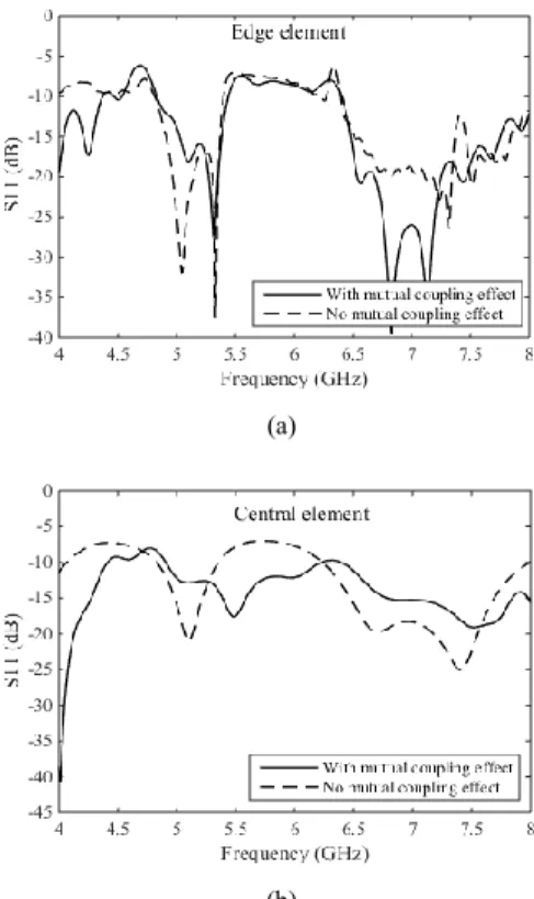
A comparison of the simulated reflection coefficient S11
from an antenna element, with and without mutual coupling effects, is shown in Fig. 5. The same weight was applied to all active elements. Simulation results are shown for an element near the array edge (Fig. 3(a)) and for one near the array centre (Fig. 3(b)).
The simulation results indicate that the element closer to the array centre is more affected by mutual coupling than the element near the edge, as the latter has better reflection coefficient S11. The non-optimum matching before 5 GHz
degrades the noise performance of the system.
In PHAROS, the Vivaldi array is placed under a 15 mm thick Plexiglas dome (Fig. 2). The dome is λ/4 thick at the central frequency of the 4-8 GHz RF band (at 6 GHz), where it has a very good match with almost 100% RF transmission. However, the transmission is reduced at the low and at the high end of the RF band. The matching of the Vivaldi antenna array is also affected by the Plexiglas.
(a)
(b)
Fig. 5. Comparison of S11 with and without coupling effect (a) edge element, (b) central element.
(a)
(b)
Fig. 6. Comparison of S11 with and without Plexiglas effect (a) edge element, (b) central element.
Electromagnetic simulations were carried out to investigate how the Plexiglas dome affects the antenna impedance match for a central element and an edge element. The results shown in Fig. 6 indicate that the low and the high end of the 4-8 GHz frequency band are both affected, with worse matching and higher ripple, in particular for the element near the array centre.
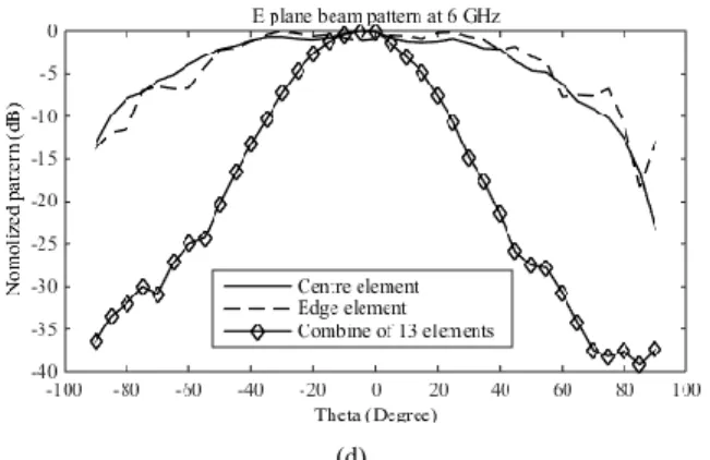
We combined 13 elements near the array centre and obtained the farfield radiation pattern of one beam with and without the vacuum Plexiglas dome beam when applying the same weight at all elements. The simulation results at three different frequencies are shown in Fig. 7 (a, b, c). The effect of the Plexiglas dome on the beam pattern is weak at all frequencies across the 4 and 8 GHz, and deteriorates (increase) the sidelobe level. Also beam patterns from a centre element, an edge element, and one combined beam by 13 elements was measured at anechoic chamber in Manchester. Results are compared at Fig. 7 (d), which indicate the extremely wide elements beam width and squeezed and smoothed shape of combined beam.
(a)
(b)
(c)
(d)
Fig. 7. Effect of Plexiglas dome applied on farfield pattern for one beam shown with 45 degree phi plane cut at (a) 4 GHz, (b) 6 GHz, and (c) 8 GHz (d) comparison of measured beam pattern by centre element, edge element and one combined beam.
III. CONCLUSION AND FUTURE WORK
A cryogenically cooled C-band PAF frond-end for radio astronomy application was presented. Electromagnetic simulation results of S11 with and without mutual coupling
indicated more effect on elements near the array centre. The effect of the Plexiglas vacuum window was investigated. The results show degraded performance of the antenna reflection coefficient, specifically towards the RF band edges, and slight degradation of beam pattern due to increased sidelobe level. Grasp and Reflect software with PO, GTD methods will be used in the future for modelling. Investigation of PAF installed at focal plane of Lovell telescope will be carried out.
ACKNOWLEDGMENT
Thanks for all the help by engineers and technicians from Jodrell Bank Observatory.
REFERENCE
[1] G. Cortes-Medellin, A. Vishwas, S. C. Parshley, D. B. Campbell, P. Perilatt, R. Black, et al., "A Fully Cryogenic Phased Array Camera for Radio Astronomy," IEEE Transactions on Antennas and Propagation, vol. 63, pp. 2471-2481, Jun 2015.
[2] D. R. DeBoer, R. G. Gough, J. D. Bunton, T. J. Cornwell, R. J. Beresford, S. Johnston, et al., "Australian SKA Pathfinder: A High-Dynamic Range Wide-Field of View Survey Telescope," Proceedings of the IEEE, vol. 97, pp. 1507-1521, Aug 2009. [3] W. A. van Cappellen, L. Bakker, and T. A. Oosterloo, "Experimental
Results of a 112 Element Phased Array Feed for the Westerbork Synthesis Radio Telescope," 2009 Ieee Antennas and Propagation Society International Symposium and USNC/URSI National Radio Science Meeting, Vols 1-6, pp. 665-668, 2009.
[4] J. Simons, M. Ivashina, J. G. b. d. Vaate, and N. Roddis, "Beamformer system model of focal plane arrays in deep dish radio telescopes," in 2005 European Microwave Conference, 2005, p. 4 pp.