iii
Nuovi materiali molecolari per la foto/elettro conversione basati su
complessi organometallici di Palladio e Iridio
Sommario
Questo lavoro di ricerca è dedicato allo sviluppo di nuovi materiali molecolari basati su complessi ciclometallati di Pd(II) e di Ir(III) per la foto/elettro conversione. Negli ultimi quindici anni, al fine di ottenere dispositivi più flessibili, più leggeri e più facilmente processabili, sono stati studiati principalmente materiali a base organica.
Tali materiali presentano però, proprio a causa della loro natura organica, molteplici svantaggi, tra i quali scarsa qualità delle interfacce formate, limitata stabilità chimico-fisica in fase di funzionamento del dispositivo, difficile trasporto di carica, scarso assorbimento nel visibile e basse efficienze di luminescenza. Al fine di migliorare le prestazioni finali dei dispositivi elettro-ottici, è stata introdotta una nuova classe di materiali che utilizza come specie attive i composti organometallici. Nell’ambito di questo lavoro di tesi, sono stati sintetizzati nuovi complessi organometallici di Pd(II) e Ir(III) e ne sono state studiate le proprietà chimico-fisiche alla base dello sviluppo di materiali efficienti per la foto/elettro conversione.
La prima parte del lavoro di tesi ha riguardato la preparazione di complessi per la conversione dell’energia solare.
In particolare sono stati sintetizzati e caratterizzati nuovi complessi fotoconduttori ciclopalladati di Rosso Nilo, contenenti basi di Schiff opportunamente funzionalizzate come leganti ancillari. Inizialmente si è scelto di utilizzare il colorante Rosso Nilo come legante ciclometallante per le sue ottime proprietà di assorbitore di luce visibile.
Il suo utilizzo ha inoltre comportato, nei complessi ottenuti, anche la separazione fisica su scala molecolare degli orbitali di frontiera HOMO e LUMO.
In particolare i due orbitali risultano essere prevalentemente localizzati su due diversi frammenti molecolari. Tale separazione induce un efficiente processo di fotogenerazione che è alla base delle ottime proprietà di fotoconduzione osservate per questa classe di composti in un ampio intervallo di lunghezze d’onda.
Per finalizzare l’utilizzo di complessi ciclopalladati di Rosso Nilo a specifiche applicazioni optoelettroniche, sono stati introdotti opportuni gruppi funzionali sia sul legante ciclometallante che sul legante ancillare.
iv
In particolare i nuovi gruppi funzionali hanno permesso di :
i) indurre proprietà mesomorfiche caratterizzate da un ampio grado di ordine in un grande intervallo di temperature e di ottenere così una nuova classe di metallomesogeni fotoconduttori;
ii) aumentare la solubilità dei complessi preparati rendendo possibile il loro utilizzo unitamente al PC61BM, nella costruzione di celle solari ad eterogiunzione
dispersa;
iii) preparare, tramite il processo di elettropolimerizzazione, film sottili fotoconduttori di elevata qualità su elettrodi modificati;
iv) poter ancorare i complessi sintetizzati a substrati di TiO2 e costruire celle solari
di tipo Dye Sensitized (DSSCs).
La seconda parte del lavoro di tesi, ha invece riguardato, la sintesi e la caratterizzazione fotofisica ed elettrochimica di complessi di Ir(III) per lo sviluppo di dispositivi elettroluminescenti.
Sebbene esista in letteratura un elevato numero di esempi di complessi cationici di Ir(III) solamente pochi complessi anionici di Ir(III) sono stati descritti finora. Inoltre, i pochi esempi riportati, contengono leganti ancillari monodentati che rendono tali complessi chimicamente instabili all’interno di dispositivi elettroluminescenti. Al fine di ampliare la classe di composti anionici di Ir(III) esistenti e di migliorane la stabilità chimica, sono stati sintetizzati nuovi complessi anionici aventi leganti ancillari bidentati di tipo catecolato e orotato. E’ stata inoltre preparata e caratterizzata una nuova serie di “soft salt” di Ir(III) contenenti i nuovi complessi anionici ottenuti accoppiati ad opportuni complessi cationici di Ir(III) già noti in letteratura.
Sono stati infine preparati e caratterizzati nuovi complessi luminescenti neutri di Ir(III) elettropolimerizzabili. Utilizzando tali complessi sono stati anche ottenuti film sottili elettrogenerati di alta qualità.
University of Calabria
Department of Chemistry
Doctorate School of Science and Technique “Bernardino Telesio”
Mesophases and Molecular Materials - XXVI Cycle
Ph.D. Thesis
Novel molecular materials
for photo/electro conversion based on
Palladium and Iridium organometallic complexes
December 2013
Supervisors
Prof. Mauro Ghedini
Dr. Nicolas Godbert
Ph.D. Candidate
Andreea Ionescu
vii
Table of Contents
Thesis Overview………….……...…………...………..…1
1st Part. Novel molecular materials based on Pd(II) for photoconversion Chapter One Introduction to Solar Energy Conversion………..……….……….7
1.1 Inorganic Solar Cells………...…………...………8
1.1.1 Silicon based solar cells...8
1.1.2 Copper indium gallium selenide (CIGS) based solar cells...8
1.2 Organic Solar Cells...11
1.2.1 Heterojunction solar cells...14
1.2.2 Dye Sensitized solar Cells (DSSCs)...19
1.3 New frontiers in solar cells...24
1.4 Concluding remarks...25
Chapter Two Nile red cyclopalladated neutral and ionic metallomesogens………...27
2.1 Introduction………...27
2.2 Nile red structure and properties...31
2.3 Research scopes...33
2.4 Photoconductive Nile red cyclopalladated metallomesogens...33
2.4.1 Synthesis………...34
2.4.2 Mesomorphic properties………...36
2.4.3 Solution electrochemistry………...……..43
2.4.4 UV/Vis spectroscopy and photoconduction……….45
2.5 Cationic cyclopalladated Nile Red metallomesogens………...50
2.6 Using Nile red as an ancillary ligand in a cyclopalladated complex...52
2.6.1 Synthesis………...…52
2.6.2 Solution electrochemistry……….……54
2.6.3 UV/Vis spectroscopy………55
2.6.4 Photoconduction………...55
viii Chapter Three
Electropolymerizable Nile red cyclopalladated complexes for bulk
heterojunction solar cell application………...59
3.1 Introduction……….…...59
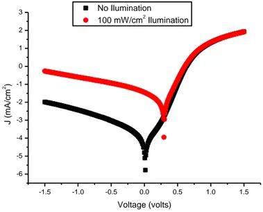
3.2 Testing a Nile red cyclopalladated photoconductor in a bulk heterojunction solar cell...62
3.2.1 Synthesis………...62
3.2.2 Electrochemistry………...63
3.2.3 Bulk heterojunction cell………..….64
3.3 Towards high quality photoconductive thin films ...72
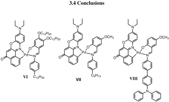
3.3.1 Synthesis………...75 3.3.2 Structural characterization………77 3.3.3 Electrochemistry………...79 3.3.4 Film photoconduction………..84 3.4 Conclusions………...87 Chapter Four Synthesis and properties of new Nile red cyclopalladated dyes and their application as sensitizers in Dye Sensitised Solar Cells...89
4.1 Introduction………...89
4.2 Nile red functionalization for post-grafting to TiO2...90
4.3 Nile Red cyclopalladated complexes containing anchoring groups…...93
4.4 Solution electrochemistry………..………...96
4.5 Testing Nile red cyclopalladated complexes in DSSCs...99
4.6 Conclusions...104
Chapter Five Conclusions...107
ix
2nd Part. Novel molecular materials based on Ir(III) for electroconversion
Chapter Six
Introduction to electroluminescence………...113
6.1 Inorganic LEDs...113
6.2 Organic Light Emitting Diodes (OLEDs) ...113
6.3 Light Emitting Electrochemical Cells (LECs)...117
6.4 Use of transition metal complexes in electroluminescent devices...118
6.4.1 Use of transition metal complexes in efficient OLEDs……..119
6.4.2 Use of transition metal complexes in efficient LECs...121
6.4.3 Phosphorescent neutral and ionic cyclometallated Ir(III) complexes used in electroluminescent devices...125
6.4.3.1 Neutral bis- and tris-cyclometallated Ir(III) complexes...127
6.4.3.2 Ionic bis-cyclometallated Ir(III) complexes...129
6.5 Concluding remarks...130
Chapter Seven Novel anionic Ir(III) complexes and their derivatives…...131
7.1. Introduction...131
7.2. Anionic cyclometallated Ir(III) complexes containing substituted bivalent ortho-hydroquinones ………..133
7.2.1 Synthesis……….134
7.2.2 Electrochemistry...136
7.2.3 Photophysical properties...138
7.3 Luminescent anionic cyclometallated Ir(III) complexes containing an orotate ancillary ligand...141
7.3.1 Synthesis………...142
7.3.2 Solution electrochemical studies………143
7.3.3 Photophysical properties………145
7.4 Ir(III) luminescent homometallic soft salts...147
7.4.1 Synthesis...147
7.4.2 Solution electrochemical studies………151
7.4.3 Photophysical properties………152
x Chapter Eight
Electropolymerizable Ir(III) cyclometallated complex……….159
8.1. Introduction...155
8.2. Research scopes……….161
8.3 Synthesis of novel bis-cyclometallated Ir(III) model complexes with Schiff bases as ancillary ligands...163
8.4 Electrochemical studies...165
8.5 Preliminary photophysical studies...168
8.6 Conclusions...169
Chapter Nine Conclusions...171
Chapter Ten Experimental details………..173
10.1 General equipment and procedures...173
10.2 Synthesis procedures……….181
10.2.1 Synthesis of novel Pd(II) complexes and of their precursors………..181
10.2.2 Synthesis of novel Ir(III) complexes and of their precursors………..…....198
Appendix I X-Ray single crystal diffraction data………207
Appendix II Indexation of PXRD pattern of columnar liquid crystals...209
References………213
1
Thesis Overview
Nowadays, research on functional materials represents one of the most important development areas in science and technology. Among the wide variety of possible functions to be introduced, those which permit the interaction with light of the obtained materials generating photoresponsive or light driven properties have been the most intensively investigated.
Furthermore, the comprehensive study of the processes involved, such as the energy flow through an organic-inorganic interface and the voltage control at a molecular level have permitted the fabrication of new efficient and sophisticated optoelectronic devices. The upcoming depletion of fossil fuels, the energy crisis and the urgent need for clean and renewable sources of energy has directed optoelectronic industry’s steps towards solar energy conversion technologies and electroluminescent devices.
In this context, an important role is played by transition metal complexes since recent advances in their exploitation has managed to take advantage from their photo-induced functions allowing their successful use in energy conversion. In particular, organometallic complexes have received a fast growing attention since their first successful use in solar cells and as molecular emitters for light-emitting devices.
In this research work, appropriate functions have been introduced onto novel transition metal complexes to allow their potential use in photo/electron energy conversion.
This thesis is divided in two main parts, dedicated to the synthesis of two different series of organometallic complexes, namely:
a) Pd(II) square planar cyclometallated complexes and b) Ir(III) octahedral organometallic compounds.
2
a) Pd(II) complexes
The first part is dedicated to the study of new Palladium organometallic based molecular materials, a new class of photoconductive complexes. Preliminary studies have been performed to propose their use in solar energy conversion in different types of solar cells. N O N O Pd N O OC12H25 OC12H25 O OC12H25 OC12H25 OC12H25 N O N O Pd N O C12H25 OC12H25 OC12H25 B O N N O Pd N OCH3 O N A C
In particular, photoconductivity measurements have been performed on the discotic metallomesogen complex A and have shown high photoconductivity values, three orders of magnitude higher than the reported values for parent cyclopalladated complexes.
Furthermore, the low molecular weight photoconductive complex B has been tested as a donor in a bulk heterojunction solar cell using PC61BM as an acceptor. Even
though the obtained device efficiency was scarce, the advantages of using an intrinsic photoconductor have been evidenced.
The availability of photoconductors with electropolymerizable fragments or mesogenic properties represents a starting key point for the development of new hybrid organic/inorganic optoelectronic devices based on molecular assembling. In this context, the electropolymerizable complex C has been synthesized and thin films have been electrogenerated.
3
b) Ir(III) complexes
Iridium organometallic emitters have been investigated for their potential use in electroluminescent devices. To this end, novel anionic complexes, forming ionic pairs when coupled with cationic Ir(III) complexes and neutral electropolymerizable species have been studied.
N Ir N N N N Ir N N O N H O O R R + -CnAn R O NBu4+ A1 : R = H A2 : R =CH3 N OCH3 O N S Ph2N S N Ir D : R = C6H4NPh2 Ph2N R R N Ir N N O N H O O R R -R O R
In particular, orotic acid has been successfully incorporated as a dianionic bidentate ligand to obtain the anionic high luminescent Ir(III) complexes A and A’. The introduction of this ancillary ligand might be a step toward the stabilisation of anionic Ir(III) complexes in LECs which until now have shown emission quenching and fast device degradation when monodentate ligand bearing complexes have been used as emitting species.
Furthermore, we have demonstrated the possibility of using such anionic complexes in the formation of Ir(III) homometallic soft salts CnAn showing enhanced photoluminescent quantum yields .
Eventually, a novel bis-cyclometallated Ir(III) neutral complex D bearing a benzothiazole-triphenylamine derivative as a cyclometallated ligand and a triphenylamine electropolymerizable Schiff base has been synthesized and electrogenerated polymeric thin films have been obtained.
5
First part
Novel molecular materials
based on Pd(II)
7 Chapter One
Introduction to solar energy conversion
Photovoltaic devices represent one of the most efficient methods of obtaining clean energy. Their working mechanism which promotes the conversion of solar radiation in electricity is based on the photovoltaic effect, discovered by Alexandre Becquerel back in 1839. This effect is defined as the potential difference between two electrodes, across a liquid or solid system, under sunlight.
The first process in the photovoltaic conversion of energy (sunlight absorption) induces an electronic transition into the absorbing material from the ground state to an excited level with subsequent formation of an opposite charged electric couple (electron-hole). In a second step, the charge separation occurs and imposes the negative charges to migrate in a preferred direction towards a specific electrode (conventionally called cathode) and the positive charges to migrate in the opposite direction, towards the anode. When the two electrodes are connected by a conductor, the photogenerated negative charges flow through the external circuit losing their energy and being collected at the cell’s anode. At the anode, each electron completes its photovoltaic process, it combines with a hole and regenerates the absorbing specie in its electronic ground state.1
The photovoltaic effect remained a laboratory curiosity from 1839 until 1959 when the first solar cell based on silicon was realized by the Bell Laboratories (1954, Chapin et al.2) presenting a 6% efficiency. Among the great number of advantages of the photovoltaic applications there are: direct sunlight conversion to electricity (from micro to megawatts), long device lifetime, zero cost of the energy source (the sun), and zero noise and pollution.
8
1.1 Inorganic solar cells
1.1.1 Silicon based solar cells
The solar cell technology has emerged on the basis of silicon technology, based on the already developed technology of transistors and integrated circuits and on the availability of single crystal silicon.3
Apart from the efforts invested in the optimization of the production process, attention has been given to improving efficiencies in order to reduce the cost. Yet, a series of loss processes limits the efficiency of devices; each semiconductor in fact can absorb only a specific part of the whole available radiation spectrum. Even more, a part of the absorbed radiation is converted to heat rather than electric energy. Other factors contribute to diminishing the efficiency among which the reflexion of the radiation incident on the cell surface, the electric resistance within the semiconductor and the connecting leads, materials purity, surface effects, and crystal defects. Moreover, the solar cells efficiency depends on temperature. In particular, for silicon based devices, the efficiency decreases with temperature.
Due to the indirect band gap semiconductor nature of silicon, rather thick layers of silicon are needed for the efficient absorption in order to compensate the low molar extinction coefficient of silicon. Taking into account the solar radiation distribution and the value of silicon band gap, for silicon solar cells a maximum efficiency of 28% can be estimated theoretically.4 However, the research is now concentrated on materials with direct band nature presenting high absorption coefficients which can be used even as very thin films. Despite the high cost and its theoretical intrinsic efficiency limit, silicon is still today the commercially dominant material for solar cells. Also considering that the silicon solar cells have a lifetime of about 20 years and that they have been already in use for almost 18 years, quite soon, the problem of their disposal will have to be faced.
1.1.2 Copper indium gallium selenide (CIGS) based solar cells
Possible inorganic alternatives to the use of silicon in solar cells have been reported.5 By using a direct band semiconductor thin layer that can show a large absorption of solar photons, devices with a thinner active layer (of ca. 1 micron order, with respect to about 100 micron sin traditional Si cells6) can be realized. Even if a wide
9
variety of metallic (Fe, Ni, Cu, Pb, Bi) binary sulphides and multi component materials like Cu2ZnSnS4 have been proposed,7 the two main technologies based on direct
semiconductor thin layers make use of CdTe and CuIn1-xGaxSe2-ySy (CIGS: 0≤x≤1,
0≤y≤2).8
Nevertheless, due to their high efficiencies - close to 20%9 -, to the facility of depositing thin films, to their stability and to the possibility of getting rid of toxic cadmium, the interest of the researcher in this field has been mainly concentrated on CIGS devices. The deposition of thin layers of CIGS may be performed under atmospheric pressure or under vacuum, either on economic substrates as glass or flexible polymer substrates. Moreover, the CIGS characteristics can be controlled by varying the stoichiometric ratio between the component elements.
In Figure 1.1 a typical structure of a CIGS based solar cell is presented. Generally, the cell is realized from a molybdenum layer on top of a glass surface, followed by a p type active CIGS layer, and an n type CdS (or another semiconductor that do not contain Cd) layer, a non doped ZnO layer, an n type transparent conductor (mainly doped with ZnO or In2O3), two metallic grids, and an anti-reflective coating.
Then the entire devise is encapsulated in such a way as to protect it from the external ambient.
10
The operation of CIGS cells, similar to the one described above for silicon cells, is based on a p-n junction. As far as the nature of the active semiconductor layer is concerned, in order to estimate the band gap, it is necessary to consider the crystalline structure of CIGS. The ternary copper chalcogenides (CGS) normally crystallizes in the tetragonal structure of the calpocrite (Figure 1.2)11
Figure 1.2. The crystalline structure of CGS (A=Cu, B=In, C=Se)10
The band gap in CuInSe2 is rather small (1.04 eV), but it may be modulated in
such a way to make it compatible to the energies associated to the solar spectrum, substituting part of the indium with gallium and part of the selenium with sulphur in the crystalline structure. The strength point of such systems is in principle the capability of tuning the band gap from 1.04 eV in CuInSe2, 1.53 eV in CuInS2, 1.7 eV in CuGaSe2
(CGS) up to 2.5 eV of CuGaS2.12
Despite their multiple advantages CIGS devices are rather complex material and the efficiency of the device is determined by the absorbent layer morphology. Besides, as the domain boundaries act as recombination centres for charges generated during the photon absorption, the deposited films must necessarily have uniform domains on micrometric scale and controlled stoichiometry, in order for the device to reach acceptable efficiencies. Generally, the techniques used to deposit these films are based on multistep processes performed in vacuum.13 Yet, solution deposition techniques have also been reported. 14
11
1.2 Organic solar cells
In order for solar cells to become the main energy source, their cost should be lowered. Nowadays, the main drawback is represented by the excessive cost of crystalline silicon production and its future disposal after use that still has to be economically evaluated properly. A potential alternative to the silicon cells is represented by organic photovoltaic devices able to produce low cost energy, providing that reasonable efficiencies and lifetimes are reached. For these reasons and also to allow a more flexible and easier architecture for solar cells, intensive researches have been dedicated in the last years to photovoltaic cells that use other materials than silicon.15 The alternative consist in using organic semiconductors since they represent a less costly alternative to inorganic semiconductors. Organic compounds were among the first to show the photovoltaic effect, successively reported in many other biologic molecules like carotene, chlorophyll, porphyrin, and phthalocyanine.16 Organic materials (conjugated polymers and dyes), may present p or n type conducting properties like “classical” semiconductors. For instance, they have high absorption coefficients that allow the construction of much thinner solar cells (thicknesses much less than a micron) and thus requiring smaller amounts of active material. Moreover, the variety of organic materials potentially obtained by an appropriate chemical design is practically infinite. With the further progress in efficiency and lifetime, organic solar cells are supposed to give strong competition to silicon solar cells in the near future. By the use of advanced materials with high charge carrier mobilities and optimized nanoscale morphology, the efficiencies of the devices are expected to increase further. The typical configuration of an organic solar cell present a sandwich planar structure where the absorbing layer stays between two different electrodes. One of the two electrodes has to be (semi)transparent to allow light to reach the photoactive layer; indium tin oxide (ITO) or an ultra thin metallic layer are commonly used, whereas the other electrode is, depending on the necessary work function, made by aluminium (or calcium, magnesium, gold etc.) (Figure 1.3).
12
Figure 1.3. General scheme of an organic photovoltaic device
In an organic photovoltaic device (Figure 1.4), photon absorption leads to the promotion of one electron from the highest occupied molecular orbital (HOMO) to the lowest unoccupied molecular orbital (LUMO) forming an exciton (a pair of hole – conduction electron). In a photovoltaic device this process must be associated by subsequent dissociation followed by the migration of the electron and the hole to the appropriate electrodes. In order to separate the opposite photogenerated charges an electric field is necessary and is generate by the difference between the redox/work potentials of the two electrodes and to complete the cell. Due to this difference the electric current flows from the electrode with the lower work function to the electrode with the higher work function.
Figure 1.4. Solar radiation absorption process and the relative position of the energy levels in an organic photovoltaic device. The electrons are captured by the aluminium
electrode and the holes by the ITO electrode. represents the work function, the electronic affinity, IP the ionization potential and Eg the energy difference between the
13
An important factor concerning the active layer in an organic solar cell is to insure absorbance in the largest possible interval of the solar spectrum. (Figure 1.5).
Figure 1.5. Solar radiation spectrum
Conjugated polymers present absorption all over the UV spectrum. Besides, whereas for crystalline silicon a100 m or more thick film is needed in order to efficiently absorb the incident radiation, in organic semiconductors, due to their direct band-gap nature the efficient absorption makes possible the use of only 100-500nm thick layers.
In a crystalline inorganic semiconductor characterized by a 3D lattice, the individual HOMO and LUMO orbitals form the valence and conduction bands of the material. However, in the great part of organic semiconductors the very weak intermolecular forces are not able to generate a 3D crystalline lattice and, consequently, the frontier molecular orbitals do not mix so strongly to form bands. Therefore, the charge transport occurs by a hopping process between localized states, rather than through the energy bands.17 This implies that the mobility of charges in organic semiconductors is rather low with respect to the inorganic ones. Besides, due to the low value of the dielectric constant in organic semiconductors, the charge separation results more difficult. In many inorganic semiconductors the absorption of a photon generates a not connected electron-hole pair, while in the organic ones, even at room temperature, the excited electron remains linked to the hole. Conjugated polymers present intermediate characteristics between inorganic semiconductors and organic dyes and, generally, it is considered that the excitons are localized on well determined molecular fragments.18
14
1.2.1 Heterojunction solar cells
As already mentioned, excitons do not separate easily in organic semiconductors. To favour excitons dissociation, the heterojunction concept has been introduced and is based on using two materials with different electronic affinity and different ionization potentials. Subsequently, the electrons are accepted by the material with the largest electron affinity and the holes are collected by the material with the smallest ionization potential (Figure 1.6).19
Figure 1.6. Relative positions of LUMO and HOMO levels of donors and acceptors in heterojunction photovoltaic cells16b
Upon illumination, the electron is promoted from the donor’s HOMO to its LUMO leaving back a hole. The electron and the hole may recombine, or may dissociate. If the accepting LUMO has a sufficiently lower energy with respect to the LUMO energy level of the donor, the excited electron is injected into the acceptor’s LUMO and thus separated from the hole.
One of the acceptors most commonly used in heterojunction cells is the (buckminster) fullerenes C60 which is quite transparent at low concentrations in
polymeric matrices and shows a high electronic conductivity (10-4 S cm-1). The first heterojunction photovoltaic cell was based on a MEH-PPV (poly[2-methyloxi-5-((2-ethylhexyl)oxy)-1,4-phenylenvinylene) spin coated film on a ITO coated glass and a gold counter electrode. This device showed a 0.04% efficiency under monochromatic radiation illumination.20 Lately, it has been proved that the photocurrent increases after insertion of a double film of C60, thus showing that the fullerene plays an essential role
in charge separation. Since then, the improved processing conditions,21 the pre- and post-fabrication treatments22 and the application of new advanced materials with new device design23 have allowed to reach efficiencies up to 8%.24
15
As an alternative to C60 it has been proved that mixing MEH-PPV with a soluble
derivative of C60 6,6-phenyl-C61-butyric acid methyl ester (PCBM) (Figure 1.7), the
charge transport considerable improves and, as a consequence, there is a drastic increase of the device efficiency.25
Figure 1.7. The molecular structure of methyl ester of the butyric acid of [6,6]-phenyl-C61 (PCMB)26
The most frequently used donor-acceptor combinations tested are poly(3-hexyltiophene) (P3HT) or poly(2-metoxy-5-(3,7-dimethyloctiloxy)-1,4-phenylenvinylene) (MDMO-PPV) as donors (Figure 1.8) and PCBM or mixtures as copper phthalocyanine-C60 as acceptors.27
S n P3HT O O n MDMO-PPV
Figure 1.8. Molecular structure of some conjugated polymers used as donors in kulk heterojunction cells
Studies have shown that excitons dissociation in heterojunction cells is more efficient at the donor/acceptor interface rather than at the electrode. Therefore, in order to reach high efficiencies, the excitons should be formed within the diffusing length from the interface (typically of the order of 10 nm) limiting the region where the absorption is useful. On the other hand, for the majority of the organic semiconductors, film thicknesses over 100 nm are needed to efficiently absorb the light. This drawback
16
might be overcome by mixing the donor and the acceptor in a single phase, thus generating a dispersed (or bulk) heterojunction cell (Figure 1.9).28
Figure 1.9. The dispersed heterojunction cell
Even if bulk heterojunction solar cells are fabricated with both polymers and small molecules, there is a head-to-head race going on in between these materials towards being technologically more important. A problem inherent to this type of cell is represented by the low miscibility of the components in the solid state. In fact, in order to have a homogeneous dispersion, a rapid evaporation of the solvent is necessary before the system reaches the equilibrium is necessary. To be used in heterojunction photovoltaic cells, the organic semiconductors must necessarily be soluble in most organic solvents. From this point of view, polymers present an advantage due to the possibility to be easier processed from solution by low cost wet technologies (spin casting, dip coating, etc.).
In these solar cells either the electron-acceptor PCBM and the hole carrier conjugated polymer are in contact with both electrodes. Despite the fact that the electrons and the holes may reach both electrodes of the system, it is generally true that the electrons go to the metallic electrode, whereas the holes are captured by the transparent electrode. It is therefore necessary to have a good compatibility between the relative positions of HOMO and LUMO of both polymer/small molecule donor and the PCMB acceptor.
An important issue to overcome in the cell stability is the phase separation which induces a discontinuity in the hopping process and thus a poor charge transport allowing a fast intramolecular recombination. Therefore, controlling the morphology of the
17
dispersive heterojunction cells represents a critical aspect. The degree of the phase separation and the dimensions of the domains depend on the choice of the solvent, the evaporation velocity, the solubility of the mixture of donors and acceptors.29
The operative mode of a bulk heterojunction solar cell is represented in Figure 1.10, which shows into details the elementary processes subsequent to the absorption of the solar radiation.
Figure 1.10. The operation principle of bulk heterojunction photovoltaic cell30
Upon light absorption mainly from the donor material (Figure 1.10 (i)) an electron-hole pair is generated in the semiconductor (ii), followed by the exciton diffusion (iii) and dissociation at the donor-acceptor interface with the consequent charge transfer from the donor to the acceptor. The mechanism (iv) represents the separation (photogeneration) due to the electric field or to the disorder within the material of the still bound exciton (also called polaron). Then the charges thus formed migrate to the respective electrodes (v). After being separated the photogenerated charges extracted from the electrodes constitute the photocurrent (vi).
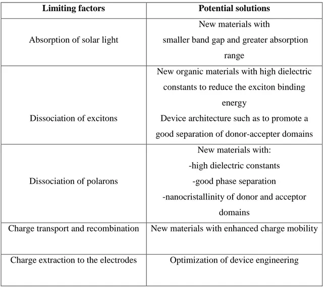
The conversion of the solar light in energy is based on the set of just described mechanisms and is thus evident that in order to increase the efficiency of the entire device, improvements of any single process are needed. The mechanisms that determine the efficiency, as well as their respective improvement margins are summarized in Table 1.1.
18
Limiting factors Potential solutions
Absorption of solar light
New materials with
smaller band gap and greater absorption range
Dissociation of excitons
New organic materials with high dielectric constants to reduce the exciton binding
energy
Device architecture such as to promote a good separation of donor-accepter domains
Dissociation of polarons
New materials with: -high dielectric constants
-good phase separation
-nanocristallinity of donor and acceptor domains
Charge transport and recombination New materials with enhanced charge mobility
Charge extraction to the electrodes Optimization of device engineering
Table 1.1. Factors that determine the efficiency of bulk heterojunction cells
Further improvements in the efficiencies of bulk heterojunction solar cells may be obtained increasing the charge mobility. According to theoretical models, ideal mobilities which makes possible the use of thicker active films are of the order of 10-1cm2V-1s-1.31 Moreover, compensating the different mobilities of electrons and holes prevents the presence of free charges that distort the electric field. Among the novel materials with similar mobilities for electrons and holes are a variety of polymers with higher hole mobilities,32 discotic liquid crystals featuring high mobilities and supra molecular self-organization,33 or carbon nanotubes that show high mobilities but challenging synthetic procedures.34
19
1.2.2 Dye sensitized solar cells (DSSCs)
The idea of the sensitization of semiconductors to light of wavelength longer than that corresponding to the band gap is an interesting convergence of photography and photoelectrochemistry, both of which rely on photoinduced charge separation at a liquid-solid interface.35 In the 60ies, dyes were chemisorbed on the semiconductor’s surface and the operating mechanism of such systems was elucidated.36 In such systems,, electrons are injected from the photoexcited dye molecules into the conduction band of n-type semiconductor surfaces. When the dyes are used as dispersed particles adsorbed onto a semiconducting surface, photoelectrodes are obtained.37 Due to its characteristics: low cost, high availability, non-toxicity and biocompatibility, TiO2
(especially in its polymorphic anatase phase) has become the mostly used material for photoelectrodes. Nevertheless, other oxide such as ZnO, SnO2 and Nb2O5
semiconductors have been also used.38
Furthermore, introducing dye-sensitized photoelectrodes in heterojunction based devices and replacing the solid junction with an electrolyte, photoelectrochemical solar cells have been obtained. The prototype of this new class of devices is the dye sensitized solar cell (DSSC), also called Grätzel cell (after its inventor name) in which both the absorption process and the charge separation occur by means of a semiconductor with crystalline morphology and large band gap doped with a dye.39 The DSSC technology has evolved up to efficiency over 11%.40
A typical DSSC (Figure 1.11) is made up of a mesoporous oxide film obtained from nanometric sintered particles deposited on a glass conducting surface. The semiconductor is sensitized with a dye monolayer. The cell is filled up with a liquid electrolyte based on usually an iodide/triiodide solution and covered with a Platinum counter electrode.
20
Figure 1.11. Outline of the dye sensitized solar cell41
The working principle of an iodide/triiodide using DSSC (Figure 1.12) is based on the absorption of a photon from the dye molecule resulting in a dye cation with promotion of an electron to the conduction band of the semiconducting oxide. The ground state of the chromophore is regenerated by accepting an electron from the reduced electrolyte, whereas the redox is regenerated by the reduction of the triiodide at the counter electrode. The electric circuit is being closed by the migration of electrons across the external load. The potential difference generated under illumination corresponds to the difference between the Fermi level of the semiconducting oxide and the redox potential of the electrolyte. On the whole, the device transforms the light into electric current without suffering irreversible chemical transformations.
21
Differently from silicon devices or organic cells, the concentration of mobile ions in the electrolyte is high enough to screen any macroscopic electric field. The charge transport mechanism is mainly diffusive, generated by concentration gradients induced by charge separation. Photoinduced charge separation is verified at the sensitized TiO2/electrolyte interface. In order to have the promotion of electrons from
the excited state of the dye to the conduction band of the semiconductor, a more reducing redox potential than the conduction band of TiO2 is required for the dye
excited state. In other words, the LUMO of the dye should have a minor electronic affinity with respect to the lowest level of the conduction band of the electrode. Analogously, for the regeneration of the dye ground state, the dye cation needs to be more oxidant than the iodide/triiodide redox pair. Then, the charges thus photogenerated migrate to the respective electrodes and enter the external circuit.
The basic functioning processes of DSSC are in equilibrium with other competitive mechanisms: the decay of the excited state of the chromophore to the ground state and the recombination of the electrons injected into the conduction band with the dye cations or the oxidized form of the electrolyte. In order for the electronic injection to be faster than the decay, the electronic coupling between the dye’s LUMO and the semiconductor should be strong enough. Then, to have an efficient regeneration of the dye, it is necessary that the kinetics of the cation reduction by the electrolyte are faster than the kinetics relative to charge recombination. This happens when the dye’s HOMO is situated far from the interface with the photoelectrode. Moreover, an ideal chromophore should absorb all the spectral wavelengths from UV up to about 920 nm and present specific anchoring groups toward TiO2 to insure intimate contact between
the dye and the semiconductor.43
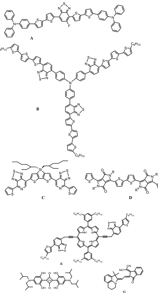
Taking into consideration the above mentioned requirements, in the last two decades a wide variety of DSSCs sensitizers have been developed, either as organometallic complexes based on porphyrins or phthalocyanines, or other organic dyes.44 Nevertheless, the best photovoltaic efficiencies (either in terms of conversion yield or the long term stability) have been obtained with Ru(II) polypyridil complexes (Table 1.2) of the general formula RuL2X2 where L= 2,2’-bipyridil-4,4’-dicarboxylic
acid and X=halide, cyanide, thiocyanide, acetyl acetate or thiocarbamate.45 Reported in 1993,46 the cis-RuL2(NCS)2 complex, called “N3” (Table 1.2) or “N719” in its partial
deprotonated form (as a di-tetrabutyl ammonium salt) has become the prototype of the sensitizer used in DSSC. The N3 complex, completely protonated, presents absorption
22
maxima at 518 nm and 380 nm and emission at 750 nm. The transition is of MLCT type: after the excitation, an electron is promoted to the from the to the * orbital, associated to the carboxylate groups responsible of the anchorage to titania, and is afterwards injected into the conduction band of the semiconductor, generating the charge separation with unit quantum yield.47 The role of the NCS groups is to increase the absorption of solar light. Therefore in this type of complexes the frontier orbitals are localized on diverse molecular moieties, with the HOMO localized on the NCS ligands and the LUMO on the anchoring groups close to the conduction band of TiO2.
In 200148 another Ru(II) complex has been synthesized and characterized, the “black dye” (tri(cianato)-2,2’,2”-terpyridil-4,4’,4”-tricarboxylate) Ru(II) and represented a milestone in the field of the DSSCs sensitizers since it absorbs within the whole visible range and near infrared up to 920 nm and it led to power conversion efficiency up to 10.4%. Nevertheless, other metals have been employed in organometallic DSSC sensitizers to form octahedral Os(II)49 or Ir(III)50 complexes, and Pt(II)51 square planar complexes (Table 1.2). Due to the high cost of Ru(II), the research has been eventually directed upon studying new synthesizers based on more economic metals. Among these, it was demonstrated that Cu(I)52 complexes of the type [CuL2]+
with ligands 2,2’-bipyridil disubstituted or phosphonic acid derivative capable of binding to the semiconductor surface (Table 1.2) present important values of IPCE (incident-photon to current efficiencies) whereas Ferrere et al.53 have synthesized Iron(II) complexes that yet have shown a non particularly high conversion efficiency.
23
Sensitizer Molecular structure Ref.
Ru (II) (N719) N N N N Ru C N S C N S COOH COO -COO -COOH 48 Os (II) N N N N N Os O O OH OH NCS PF6 -49 Pt (II) N N HOOC HOOC Pt S S CN COOEt 51 Cu (I) N N (RO)OC CO(OR) 1 R=H 3 R=Me N N CO(OR) (RO)OC Cu + N N 2 R=H 4 R=Me (RO)OC CO(OR) N N CO(OR) (RO)OC Cu + 52 Ir (III) N N O O OH OH O O Ir 50
24
1.3 New frontiers in solar cells
In the attempt to develop new efficient solar devices, organic and inorganic materials and the respective specific technologies have been mixed. Organic sensitizers often limit light-harvesting ability because of their low absorption coefficients and narrow absorption bands. To overcome this issue, inorganic sensitizers such as quantum dots54 have been introduced. Intense band-gap light absorption by these inorganic sensitizers, however, has not allowed high performance in quantum conversion and photovoltaic generation; significant losses in light utilization and/or charge separation are found at the semiconductor-sensitizer interface. In this context, organic-inorganic lead halide perovskite compounds such as CH3NH3PbBr3 and CH3NH3PbI3 have been
successfully introduced as visible-light sensitizers in photoelectrochemical solar cells showing a 3.8% efficiency. In addition to being synthesized from abundant sources (Pb, C, N, and halogen), these perovskite materials present unique optical and excitonic properties, and show high electrical conductivity.55
In this context, very recently,56 a perovskite based planar heterojunction solar cells has been built by vapour deposition allowing the formation of a thin nanostructured film- and showed over 15% efficiency and a 1.07 V open-circuit voltage. Figure 1.13 shows the scheme of this planar heterojunction p-n solar cell. From the bottom (the side from which the light is incident), the device is constructed on fluorine-doped tin oxide (FTO)-coated glass, coated with a compact layer of n-type TiO2
sensitized with the absorbing CH3NH3PbI32xClx perovskite which is then deposited on
the n-type compact layer, followed by the p-type hole conductor, 2,29,7,79-tetrakis-(N,N-di-p-methoxyphenylamine)9,99-spirobifluorene (spiro-OMeTAD), which ensures the selective collection of holes at the silver cathode.
25
a) b)
Figure 1.13. Generic structure of a heterojunction perovskite solar cell; crystal structure of the perovskite absorber adopting the perovskite ABX3 form, where A is methyl
ammonium, B is Pb and X is I or Cl.
1.4 Concluding remarks
After more than two decades of research and development, organic solar cells represent nowadays a real alternative to the use of silicon based solar cells. The intensive research efforts dedicated to this field have resulted in an increase in the efficiencies from 0.001% in 1975 to 8% for bulk heterojunction solar cells and 11% for dye sensitized solar cells. The major strength points of using organic materials are: i) the expected high-efficiency per unit cost ratio, ii) the simplicity in fabrication and processing, and iii) their mechanical flexibility iv) their light weight features. The main drawbacks of using organic materials in solar cells arise instead from their short diffusion length and from low absorption of the resulting active layer.
The addition of an inorganic acceptor material to form an organic–inorganic hybrid solar cells should theoretically improve the performance of OPV, due to additional advantages such as enhanced absorption and improved charge transport characteristics. However, to date, the efficiency of hybrid solar cells have been very low, when compared to their all-organic counterparts.57
Even if, to date, silicon based solar cells are still more efficient than organic solar cells, important issues such as disposal of the used silicon and the limited theoretical efficiency need to be faced regarding inorganic solar cells. On the contrary, organic solar cells present the advantage of the non-limited efficiency and the availability of different low cost architectures.
26
In this context, it appears clear that further efforts need to be invested in the design and developments of novel hybrid organic/inorganic materials with high absorption properties and good charge transport leading to significant increase of efficiencies in order to allow their implementation in low cost large scale solar panels. In this context, the first part of this thesis is dedicated to the development on new absorbing species bearing functions inducing supramolecular organization and photoconductive properties.
A selection of reviews concerning recent developments in solar energy conversion, ordered by topic, is collected in Table 1.3.
Topic First author (Year) Reference
Silicon solar cells A. Martin (2013)
S. Binetti (2013)
58a 58b
CIGS P. U. Singh (2010) 59
Organic—inorganic hybrid solar cells: a comparative review
M. Wright (2012) 57
Bulk heterojunction solar cells K. Vandewal (2013) Y. Lin (2012) R. P. Singh (2013)
60a 60b 27b Dye sensitized solar cells B. Bozic-Weber (2013)
J. Gong (2012)
61a 61b
27 Chapter Two
Nile Red cyclopalladated neutral and ionic metallomesogens 2.1 Introduction
In recent years, a rising interest in low-cost, flexible and easy to process electronic devices motivated the development of organic electronic technologies.62 Applications of organic semiconducting materials include photodetectors, sensors, thin film transistors, lasers, and light emitting and photovoltaic devices.63 Semiconductors, where charge carrier generation is promoted in situ by light absorption, are called photoconductors.64 The photogeneration process at the origin of photoconduction can be either extrinsic65 (when assisted by injection at electrodes or defect sites, or induced by doping) or intrinsic66 (when a charge-pair state is formed and after its dissociation the resulting holes/electrons can drift through the bulk material). The best photoconductors present high photogeneration efficiency as well as high charge mobilities.
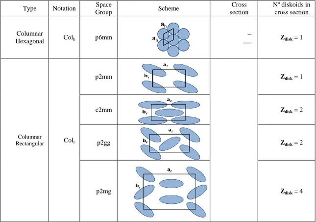
Over the last decade, discotic liquid crystals have received particular attention as semiconducting materials due to their columnar organisation which enhances charge mobility.67 Indeed, since their discovery by Chandrasekhar in 1977,68 discotic liquid crystals have attracted the attention of many research groups due to their multiple potential applications. A typical discotic mesogen generally includes a central aromatic core functionalized with flexible chains. The two main types of discotic liquid crystal mesophases forms are nematic and columnar. In the nematic phase, discs present orientational order, while in the columnar phase the discs pile into column (Figure 2.1) to form six different columnar phases: hexagonal columnar, rectangular columnar, columnar oblique, columnar plastic, helical, and columnar lamellar.69
28
Figure 2.1. Schematic representation of a) the discotic nematic and b) the columnar phase70
Due to their large polyaromatic cores inducing efficient - stacking, many triphenyl,71 porphyrin72 or hexa-peri-hexabenzocoronene73 derivatives properly embedded with peripheral aliphatic chains (Figure 2.2) have been studied in the context of organic discotic mesogens.
N NH N NH CH3 CH3 CH3 CH2CH3 CH3 CH3 CH2CH3 CH3CH2O C O XR XR XR XR XR XR X = S, R = alkyl X = O, R= alkyl 2 RX XR RX XR RX XR X = CH2 , R = n-C11H23 , (CH2CH2O)3CH3, (CH2)3(CF2)2CF3 1 3
Figure 2.2. Triphenyl (1),71 porphyrin (2)72 and hexa-peri-hexabenzocoronene (3)73 derivatives
Indeed, along the column stacks of discotics, for charge mobilities several orders of magnitude higher than in other directions have been measured, and a hole mobility as high as 1.4 cm2 V-1 s-1 has recently been reported for tri-indole-based discotic liquid crystals. This particularly high charge mobility was obtained by reducing the stacking distance between molecules and preserving a high intramolecular order along the columns.74
For most organic compounds, the photoconduction is limited by the low photogeneration efficiency. To overcome this limitation, organic devices must often be sensitized by incorporation of pigments such as phthalocyanines, squaraines, perylenes or azopigment derivatives, or by means of a double layer architecture where the photosensitizing layer is in contact with a transport layer.64,75 Another
29
approach, which is yet to be developed but whose preliminary results are encouraging, is the use of photoconductive metallomesogens. Metallomesogens combine the properties of transition-metal centres with the self-organisation of the liquid crystalline state, hence high absorption properties at higher wavelength are expected, in contrast to fully organic liquid crystals. In this context, a new class of photoconductive cyclometallated complexes has been synthesised and characterised in the CEMIF.Cal Laboratories. These complexes feature a 5-membered Pd(II) or Pt(II) metallocycle, obtained by using a H(C^N) cyclometallated ligand such as azobenzene H(Az), benzo[h]quinoline H(Bq) or 2-phenylpyridine H(Pp), and a 6- membered metallocycle formed by a Schiff base H(O^N) ancillary ligand (Figure 2.3). N C N O M M = Pd/Pt N CH H(C^N) Cyclometallated ligands N N N N ; ;
H(O^N) Schiff Base ligand
N HO OCnH2n+1 CnH2n+1 OH N Example: N O OCH3 CH3 N N Pd H(Az) H(Bq) H(Pp) H(BSCn) (Az)Pd(BSC1) (C^N)M(BSCn) n=1,6
Figure 2.3. Photoconductive cyclometallated complexes
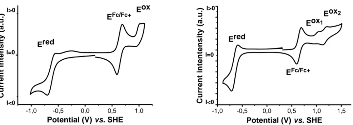
Some of these complexes have shown excellent photorefractive properties either dispersed into a polymeric matrix76 or in their bulk amorphous state77 and their excellent photogeneration–photoconduction properties were recently correlated with their chemical structure.78 In fact, the HOMO and LUMO distributions are separated by the metal centre, with the HOMO mainly localised onto the Schiff base moiety while the LUMO is mainly distributed onto the cyclometallated ligand. Moreover,
30
theoretical computations have shown that the first singlet and triplet excited states exhibit a distorted geometry around the metal centre when compared to the ground state (Figure 2.4). Such distortion may further delay the return to the ground state of excited molecules, hence enhancing charge separation efficiency, leading to the excellent photoconductive behaviour observed for this new class of complexes.
Figure 2.4. Comparison of the S0 (singlet) and T1 (triplet) structures
(the last one is the transparent one)
Furthermore, taking advantage of this peculiar HOMO/LUMO distribution, in order to enhance the charge separation during photogeneration processes, it is expected to be useful to incorporate donor building block onto the Schiff base (ancillary ligand) and acceptor building block onto the cyclometallated ligand (Figure 2.5).
h
Figure 2.5. Schematic representation of (C^N)Pd(O^N) systems, physical separation of photogenerated charges by intramolecular charge transfer.
As illustrated in Figure 2.6 (complexes A and B), by incorporating long alkyl chains at the periphery of both ligands, discotic mesophases were obtained.79 Furthermore, by changing the chemical nature of the linker between the cyclometallated core and the alkyl chains (ester for I vs. ether for II), it was possible to tune the absorption
31
properties of the resulting complexes and to obtain cyclopalladated liquid crystal complexes photoconductive at room temperature from UV-Vis to near IR (from 300 to 800 nm).79 Due to their high viscosity, low mesophase temperature range (from room temperature to ca. 50 oC) and low degree of order of the columnar organisation, the photoconduction of these complexes could be, however, increased by only one order of magnitude upon thermal annealing, when compared to the same property in non-annealed samples. NN O O O O OC12H25 C12H25O C12H25O C12H25O C12H25O OC12H25 N O O O O OC12H25 OC12H25 OC12H25 OC12H25 OC12H25 OC12H25 O Pd NN O O OC12H25 C12H25O C12H25O C12H25O C12H25O OC12H25 N OC12H25 O OC12H25 OC12H25 OC12H25 O Pd OC12H25 A B
Figure 2.6. Photoconductive discotics (A, B)
In general, in order to improve both the stability and the degree of order of discotic mesophases, several approaches have been developed and are commonly used, such as: (i) increasing the size of the discoid core,80 (ii) the introduction of secondary interactions such as hydrogen bonds,81 and (iii) the generation of helicoidal conformation that induce a higher degree of order.82
2.2 Nile Red structure and properties
In order to increase absorption in cyclopalladated complexes like (Az)Pd(BSC6), (Bp)Pd(BSC6) and (Pp)Pd(BSC6) (Figure 2.3), one possible strategy is to choose a dye with a molecular structure similar to the cyclometallating azobenzene, benzoquionoline and phenylpyridine. A rightful candidate may be 9-diethyl-amino-5H-benzo[a]fenoxazin-5-one, commonly named Nile Red (Figure 2.7).
32 N O N O H(NR) 1 2 3 4 6 5 7 8 9 10 11 a) b)
Figure 2.7. a) Molecular structure and b) absorption spectrum of Nile Red, H(NR)
While its fluorescent and solvatochromic properties have been largely employed in biological labelling applications,83 Nile Red has been poorly used as organometallic ligand and only recent studies reported the possibility of cyclopalladation (Figure 2.8a).
O N O N O O OCH3 C14H29O OC14H29 OC14H29 O O OCH3 O O OC14H29 OC14H29 C14H29O Pd O O OCH3 C14H29O OC14H29 OC14H29 O O OCH3 O O OC14H29 OC14H29 C14H29O a) b)
33
Taking advantage of such tools, a red luminescent cyclopalladated complex exhibiting a columnar phase over a broad temperature range (35–173 oC) has been obtained.This discotic mesogen was synthesized by cyclopalladation of the Nile Red dye using a polyalkylated derivative of an acetylacetone-like species, the curcumin as an ancillary ligand and represents the first example of cyclometallation of such dye molecule (Figure 2.8b).84
2.3 Research scopes
Taking advantage of the capacity of Nile Red to undergo cyclopalladation, the aim of this work is to synthesize novel complexes structurally similar to the photoconductive parent complexes (Az)Pd(BSC6), (Bp)Pd(BSC6) and
(Pp)Pd(BSC6) (Figure 2.3) with enhanced absorption properties. On the other hand, in the context of the design of new discotics, following the examples described above, by incorporating different functionalities into the molecular structure, the liquid cristallinity temperature range could be increased. Using such tools, novel UV-vis photoconductive discotics could be obtained.
2.4 Photoconductive Nile Red cyclopalladated metallomesogens
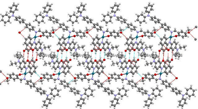
In the present work we report the synthesis and characterisation of two new room temperature photoconductive discotic liquid crystals, obtained by using either Nile Red or a polyalkylated Nile Red derivative as cyclopalladated ligands and a polyalkylated Schiff base as an ancillary ligand. The incorporation of Nile Red as a cyclometallated ligand has proven to maintain the physical separation of the frontier orbitals on their respective fragment, as shown by comparative cyclic voltametry studies, leading to efficient photoconduction over a wide wavelength window. The Nile Red fragment also induces, via formation of hydrogen bonded interactions through paired molecules, a wide temperature range of liquid-crystallinity with a high degree of order.
34
2.4.1 Synthesis
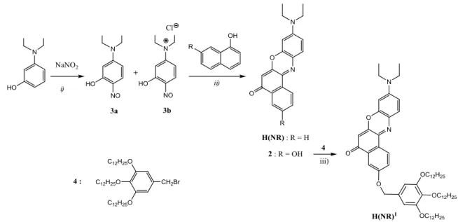
The synthesis of both complexes I and II (Scheme 2.1) was achieved in two steps through the formation of their corresponding Pd(II) acetato-bridged intermediates (1 and 1’ respectively) obtained by cyclometallation of either Nile Red H(NR) or the Nile Red derivative H(NR)1 with Pd(II) acetate, as previously described for the cyclometallation of H(NR).85 The bridge cleavage of 1 and 1’ was performed using the Schiff base H(O^N)1, prepared according to the previously reported procedure.79 N O N O Pd O N O N O Pd(OAc)2 Rn Rn O N O N O Pd Rn N O OC12H25 OC12H25 O OC12H25 OC12H25 OC12H25 H(NR) R1 = H H(NR)1 R 2 = 1 : n = 1 1' : n = 2 i) ii) N OC12H25 OC12H25 O OC12H25 OC12H25 OC12H25 HO H(O^N)1 = H(O^N)1 O OC12H25 OC12H25 OC12H25 I : n = 1 II : n = 2
Scheme 2.1. Experimental conditions: i) acetic acid, 55oC, 4h; ii) ethanol/dichloromethane, r.t., 5 d.
H(NR) and its hydroxy-derivative 2 (Scheme 2.2) were prepared in two steps by slight modifications of previously reported syntheses.86–88 Nitrosation of 3-diethylaminophenol gave a mixture of 5-diethylamino-2-nitrosophenol (3a) and its hydrochloride salt (3b) in a 1 : 2 ratio, as determined from the 1H-NMR spectrum of the mixture (Figure 2.9).
35
Scheme 2.2. Experimental conditions: i) HCl, H2O, 0-5 oC, 4h: ii) DMF, 70 oC, 8h;
iii) K2CO3, KI cat., DMF, 130 oC, 8h.
Figure 2.9. Aromatic region of the 1H NMR spectrum of the mixture 3a and 3b showing the relative ratio of the two components
36
Since both 3a81 and 3b80 have been successfully used in cycling reactions for obtaining Nile Red derivatives, the mixture was used in the second step without any further purification. H(NR) and 2 were then obtained by reaction of 3a,b with naphthol and 1,7-dihydroxynaphthalene, respectively. H(NR)1 was finally obtained by etherification of 2 with 3,4,5-tris(dodeciloxy)bromomethylbenzene 4.79
Complex (NR)Pd(BSC6), analogous to the photoconductive complexes
(C^N)Pd(BSC6) (Figure 2.3), was synthesised with the purpose of carrying out a complete electrochemical study in order to determine the influence of the Nile Red fragment onto the frontier orbitals of the resulting cyclometallated complexes. (NR)Pd(BSC6) was obtained through the rupture of the bridge intermediate 1 by the Schiff base H(BSC6) following the pathway previously described.
2.4.2 Mesomorphic properties
At room temperature, the new cyclopalladated complexes I and II (Scheme 2.1) are dark blue waxy solids. Their thermal behaviour was investigated by using polarized optical microscopy (POM), thermogravimetry (TGA) and differential scanning calorimetry (DSC). Both compounds, as observed by TGA, are thermally stable until 180 oC. While complex I shows typical DSC diagrams of liquid crystalline phases through repetitive scans of heating–cooling cycles (Table 2.1, DSC traces are reported in Figure 2.10), for complex II no thermal transitions were observed by DSC, probably due to its high viscosity and a clearing point close to its decomposition temperature. It is noteworthy that for complex I the DSC traces obtained on the third and successive heating/cooling cycles are identical, indicative of the high stability and reversibility of the mesophases. The mesophases of complex I, observed by POM upon slow cooling from the isotropic phase (Figure 2.11), show typical birefringent textures of liquid crystals but, their identification necessary in order to identify the specific mesophase was not possible for the absence of perceptible specific motifs.
37
Complex DSC scan Transitional properties, T (ºC), [H in kJ mol-1] I 1st heating Waxy powder – 177 [72.6] - I
1st cooling I-139 [29.5] – Colr’ – 62 [11.0] – Colr – 37 [3.6] –
frozen
2nd heating Frozen– 33 [4.0] – Colr’ – 77 [11.6] – Colr – 160
[24.4] - I
2nd cooling Identical data of 1st. cooling 3rd heating
cycle
Identical data of 2nd. cycle
Table 2.1. Thermodynamic data for all thermal transitions observed by DSC for complex I during 3 heating-cooling cycles (Colr: columnar rectangular, I: isotropic
liquid)
38
Figure 2.11. Birefringent textures of complex I observed under POM
Unequivocally, the mesophase determination was achieved by powder X-ray diffraction studies (PXRD) at variable temperatures. Both complexes I and II present a columnar rectangular organisation (Colr). The indexations of the PXRD patterns
performed using a LCDiXRay, a newly developed program89 and the cell parameters of complexes IV and V are presented in Table 2.2, together with the previously reported data of complexes A–C, for direct comparison.
39
No. Temp. dobs
(Å) hk dcalcd (Å) Mesophase and cell parameters Density (g.cm-3) Molecules No. in Unit Cell (z) A[12] r.t. 32.83 10 32.83 Col h, p6mm - 19.32 11 18.95 ah = 37.9 Å 4.47 hch Sr = 1245Å2 B[12] r.t. 31.07 10 31.07 Col h, p6mm 1.2 0.98 18.67 11 17.93 ah = 35.9 Å 16.24 20 15.53 Sr = 1115Å2 12.24 21 11.74 4.36 hch - 3.44 h0 - C16 140ºC 46.46 20 46.46 Colr c2mm 1.2 4.24 38.57 11 38.57 ar = 92.9 Å On second heatin g cycle 24.53 31 25.01 br = 42.4 Å 21.78 02 21.20 Sr = 3939Å2 14.07 03 14.13 12.83 33 12.86 4.56 hch - 3.39 h0 - I 125ºC 32.52 20 32.52 Colr , p2gg 1.2 4.08 18.62 02 18.62 ar = 65.0 Å 14.14 32 14.14 br = 37.2 Å On cooling from1 60oC 11.42 23 11.61 ar/br = √3 9.17 14 9.22 Sr = 2421 Å2 8.03 44 8.09 7.66 54 7.60 6.70 45 6.77 4.27 hch - 3.85 h0 - II r.t. 35.81 20 35.81 Colr, c2mm 1.2 3.84 On cooling from1 60oC 21.19 02 21.19 ar=71.62 Å 14.36 13 13.85 br=42.38 Å 12.53 33 12.15 Sr=3.035 Å2 7.28 55 7.29 4.42 hch - 4.03 ho - 70 oC 36.74 Highly disordered L.C. On 2nd heatin g cycle 14.42 a Calculated with a
h = 2d10/√3 (Colh);and ar = 2d20, br =2d02 (Colr) b Not Calculated in absence of
h0 signal.