UNIVERSITY
OF TRENTO
DEPARTMENT OF INFORMATION AND COMMUNICATION TECHNOLOGY
38050 Povo – Trento (Italy), Via Sommarive 14 http://www.dit.unitn.it
UWB
RADARS FORB
IO-M
EDICALS
ENSING:
A
TTENUATIONM
ODEL FORW
AVEP
ROPAGATION IN THEB
ODY AT4GH
ZCarlos Bilich
www.carlosbilich.com.ar
July 31
st, 2006
UNIVERSITY OF TRENTO. TECHNICAL REPORT # DIT-06-051 1
Abstract—The aim of this work is to compute the attenuation
that an electromagnetic wave will suffer when traversing the human body. The frequency under consideration is 4GHz, but a calculation in 1.5GHz is also provided to contrast this formulation against the results of the literature. The calculation is done considering a uniform plane wave normally incident upon the skin, which traverses the chest, reach the heart and bounces back.
Index Terms—UWB radar, electromagnetic wave propagation,
contact-less vital signs monitoring.
I. MOTIVATION
HE feasibility study done for PhD Thesis proposal named
‘Bio-Medical Sensing using Ultra Wideband Communi-cations and Radar Technology’, submitted for the
Interna-tional Doctorate School of the University of Trento on Janu-ary 2006 [1], in its section 3.1.2 included a calculation of the propagation loss based on the attenuation model published in [2]. It was then noted that the model was done for a continu-ous wave at 1.5GHz and would require a future revision for 4GHz which is the central frequency of the UWB system be-ing considered for the proposal.
Apart from this, feedback received after the blind review process, suggested that the model described in [2] has some inaccuracies that must be amended, and in order to do that, proposed to refer directly to the three papers of Gabriel et al. [3]–[5] to come up with a new revised model.
II. INTRODUCTION
Since [2] does not clearly describe what assumptions where made to build the model, for the sake of this work it is assumed that the waves travel perpendicularly (normal incidence) to the planar interface formed by multiple strata of
* Manuscript prepared on July 31, 2006. This work was done as part of the
research for the PhD Thesis proposal named “Bio-Medical Sensing using
Ultra Wideband Communications and Radar Technology”, submitted for the
International Doctorate School of the University of Trento on January 2006, tutored by Prof. Imrich Chlamtac with the help of the Professors Renzo Azaro and Andrea Massa from the University’s Electromagnetic Diagnostic Group.
C. G. Bilich is a PhD student at the Department of Information and Telecommunication Technology of the University of Trento, TN 38100, Italy (http://www.dit.unitn.it/), phone: 408400 ext. 706; fax: +39-0461-421157; e-mail: [email protected]; and a Research Staff Member of the “Center of Research and Telecommunication Experimentation for Networked Communities” (http://www.create-net.org).
lossy media which represent the different layers of tissue that constitute the chest and the path from the skin to the heart. The thickness of each of these layers as approximated by [2] are given in Table I.
Fig. 1 shows the simplified model used to compute the transmission and reflection coefficients.
The expressions for the coefficients, impedances and average power densities are taken from [6] and reproduced here for convenience:
Transmission coefficient at the interface:
1 2 2 2 η η η + = b T
Reflection coefficient at the interface:
1 2 1 2 η η η η + − = Γb
UWB radars for Bio-Medical Sensing: Attenuation
Model for Wave Propagation in the Body at 4GHz
Carlos G. Bilich* www.carlosbilich.com.ar
T
TABLEI
THICKNESS OF THE DIFFERENT LAYERS OF MEDIA ENCOUNTERED IN THE CHEST OF A PERSON ALONG THE PATH FROM THE SKIN TO THE HEART [2]
Media Type Thickness [cm] Fat 0.96 Muscle 1.35 Cartilage 1.16 Lung 0.578
Fig. 1. Simple model to represent the reflection and transmission at normal incidence by a planar interface of a transverse electromagnetic (TEM) wave. E and H are the electric and magnetic field intensities in [V/m] and [A/m], and the superscript i, t and r stand for: incident, transmitted and reflected respectively. [6]
UNIVERSITY OF TRENTO. TECHNICAL REPORT # DIT-06-051 2
It is shown in Tables II and II that the condition for good dielectric 1 2 << ⎟ ⎠ ⎞ ⎜ ⎝ ⎛ ωε σ (1)
is satisfied quite well for the tissues and the frequencies being considered. This allows the usage of the following approximations for the field parameters:
Attenuation Constant: [m-1] ε µ σ α 2 ≅ (2) Intrinsic impedance: ] [Ω ≅ ε µ η
The transmitted and received average power density can be written as: ] [W/m2 i av z b t av T e S S ⎟⎟⋅ ⋅ ⎠ ⎞ ⎜⎜ ⎝ ⎛ = 2 −2 2 2 1 α η η ] [W/m2 i av z b r av e S S = Γ 2⋅ +2α2 ⋅ where i av
S is the incident power and Tband Γbtake real values due to the condition (1).
III. THE 1.5GHZ MODEL REVISITED
The expressions listed in section II and the field parameters extracted from Gabriel’s papers were used to compute the values of Table II.
The values of Table II were used to compute the attenuation that will suffer a hypothetical electromagnetic pulse on its way to the heart and bounce back. The results are plotted in Fig. 2 following the same layout proposed in [2].
Comparing the final value of attenuation obtained from Fig. 2 with the model and the values reported in [2], there are only approximately 2.80 dB of difference (~37.8 vs. ~35 dB) between the two. Therefore, it can be said that this model TABLEII
FIELD PARAMETERS,ATTENUATION,TRANSMISSION AND REFLECTION COEFFICIENTS FOR 1.5GHZ
Media σ εr (σ/ωε)2 α η Γb Tb η1/η2*|Tb|2 Tb [dB] η1/η2*|Tb|2 [dB] air 0.00 1.00 0.00 0.00 376.73 fat 0.09 5.50 0.03 6.83 160.64 -0.40 0.60 0.84 -2.23 -0.77 Muscle 1.75 55 0.15 44.45 50.80 -0.52 0.48 0.73 -3.18 -1.37 Cartilage 1.00 40 0.09 29.78 59.57 0.08 1.08 0.99 0.33 -0.03 Lung 0.55 20 0.11 23.17 84.24 0.17 1.17 0.97 0.69 -0.13 Heart 1.50 60 0.09 36.48 48.64 -0.27 0.73 0.93 -1.35 -0.32 σ:Conductivity of the medium [S/m]; εr: Relative Permittivity; ω = 2πf: Frequency [rad/s]; α: Attenuation constant [1/m]; η:
Intrinsic impedance [Ω]
It is important to notice that the factor (σ/ωε)2 is almost always << 1 which assures the validity of condition (1)
TABLEIII
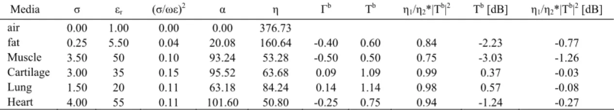
FIELD PARAMETERS,ATTENUATION,TRANSMISSION AND REFLECTION COEFFICIENTS FOR 4GHZ
Media σ εr (σ/ωε)2 α η Γb Tb η1/η2*|Tb|2 Tb [dB] η1/η2*|Tb|2 [dB] air 0.00 1.00 0.00 0.00 376.73 fat 0.25 5.50 0.04 20.08 160.64 -0.40 0.60 0.84 -2.23 -0.77 Muscle 3.50 50 0.10 93.24 53.28 -0.50 0.50 0.75 -3.03 -1.26 Cartilage 3.00 35 0.15 95.52 63.68 0.09 1.09 0.99 0.37 -0.03 Lung 1.50 20 0.11 63.18 84.24 0.14 1.14 0.98 0.57 -0.08 Heart 4.00 55 0.11 101.60 50.80 -0.25 0.75 0.94 -1.24 -0.27 As in Table II, it is important to notice that the factor (σ/ωε)2 is almost always << 1 which assures the validity of condition
(1). Also, it is clear the huge increase of the attenuation constant due to the increase that the higher frequency produces in the conductivity σ. -80.00 -70.00 -60.00 -50.00 -40.00 -30.00 -20.00 -10.00 0.00 0 0.01 0.02 0.03 0.04 0.05 0.06 Depth [m] Atte nu a tio n @ fc = 4 GHz [dB]
air fat muscle cartilage lung heart
Fig. 3. Same as Fig. 2 but at 4GHz. It is important to notice that the attenuation almost double the value at 1.5GHz.
-80.00 -70.00 -60.00 -50.00 -40.00 -30.00 -20.00 -10.00 0.00 0 0.01 0.02 0.03 0.04 0.05 0.06 Depth [m] Att e n u a tio n @ fc = 1.5GH z [d
B] air fat muscle cartilage lung heart
Fig. 2. Attenuation that would suffer a hypothetical pulse on its path from the transceiver antenna, located at a distance of 1cm from the skin, to the heart and bounce back, following the layout proposed in [2].
UNIVERSITY OF TRENTO. TECHNICAL REPORT # DIT-06-051 3 resembles quite well the one reported in [2], where the
discrepancies encountered are admissible and most probably due to small differences in the permittivities and conductivities as taken from the graphs of Gabriel’s paper.
IV. THE 4GHZ MODEL
Having validated the procedure at 1.5GHz, it follows the calculation at 4GHz which is the frequency envisioned for the proposal. Table II shows the values and parameters for 4 GHz. The results are plotted in Fig. 3.
Comparing Fig. 2 with Fig. 3 one can notice how the attenuation suffered by the wave has almost doubled in value for 4 GHz. Analyzing the causes of this change, one can mention that even though there is not a significant difference in permittivity of the many tissues in consideration between 1.5 and 4 GHz, the conductivity differences are considerable. A close look to Tables II and III shows that the value of σ increase roughly by a factor of 2 to 3. Therefore, given that εr
remains practically the same, the increase in σ makes the value of α in (2) increasing by the same proportion.
V. CONCLUSION
The calculations of section III very much approximate the values reported in [2], which confirms the validity of that model for central frequencies of 1.5 GHz. In Section IV, Gabriel’s values for the different constituents were used to build a similar model for 4 GHz. The attenuation is much more significant than the value initially portrayed in [1]. This result calls for a review of the feasibility study done in [1], especially in section 3.1.2 “Propagation loss”.
Finally, this work fulfils one of the milestones enumerated in the proposal [1] with regard to the refinement of the propagation model. A further improvement of the model will be proposed considering UWB instead of short band pulses, and measurements using the recently acquired PulsON 210 UWB evaluation kit from Time Domain Corp. will be done to validate the models [7].
ACKNOWLEDGMENTS
I would like to thank the staff of the Electromagnetic Diagnostic Group (ELEDIA) of the University of Trento, especially to Professors Massa and Azaro for helping me with the review of my PhD proposal and the designation of the review committee that provided abundant and useful feedback
Also special thanks to Professor Imrich Chlamtac to make possible the acquisition of two wonderful UWB transceivers from Time Domain to proceed with the experimental part of this proposal.
REFERENCES
[1] Bilich, C.; “Bio-Medical Sensing using Ultra Wideband Communications and Radar Technology”; PhD Proposal, submitted for the 20th Cycle of the Program in Information and Communications
Technologies; Department of Information and Telecommunications Technology; University of Trento; Italy; January 2006. Available: http://eprints.biblio.unitn.it/archive/00001045/
[2] Staderini, E.M.; “UWB radars in medicine”; Aerospace and Electronic
Systems Magazine, IEEE, Volume 17, Issue 1, Jan. 2002 Page(s)13 –
18.
[3] C.Gabriel, S.Gabriel and E.Corthout: "The dielectric properties of biological tissues: I. Literature survey", Phys. Med. Biol. 41 (1996), 2231-2249.
[4] S.Gabriel, R.W.Lau and C.Gabriel: "The dielectric properties of biological tissues: II. Measurements in the frequency range 10 Hz to 20 GHz", Phys. Med. Biol. 41 (1996), 2251-2269.
[5] S.Gabriel, R.W.Lau and C.Gabriel: "The dielectric properties of biological tissues: III. Parametric models for the dielectric spectrum of tissues", Phys. Med. Biol. 41 (1996), 2271-2293.
[6] Balanis, C.; Advanced Engineering Electromagnetics. John Wiley & Sons; USA, 1989; ch. 5.
[7] Time Domain Corporation, “P210 Evaluation kit: Fostering Ultra-Wideband Innovation and Integration”. [Online] last accesed: 07/31/2006. Available: