Universit`
a di Pisa
Facolt`
a di Ingegneria
CORSO DI LAUREA SPECIALISTICA IN INGEGNERIA INFORMATICA
Tesi di Laurea
Design and implementation of a
software-defined VHF-DSC
multichannel monitoring system
Candidato Relatori
Luca Melette
Prof. Marco Luise
Sommario
Nell’ambito di questa tesi vengono proposti il progetto e l’implementazione di un sistema per il monitoraggio delle comunicazioni marittime (vocali e digitali) in banda VHF, uti-lizzando la tecnologia Software Defined Radio.
Partendo dal framework GNU Radio e la periferica di acquisizione (Universal Software Radio Peripheral ) collegata ad esso, `e possibile ricevere simultaneamente tutti i canali VHF con una sola interfaccia radio. A partire dalla porzione di spettro acquisito, tutte le successive elaborazioni del segnale sono effettuate via software da un applicativo server, che effettua l’analisi e demodulazione della porzione di banda acquisita, e da un applica-tivo client che permette all’utente la selezione e l’ascolto di uno dei canali voce.
La comunicazione tra client e server avviene tramite IP (UDP/Multicast), consentendo la distribuzione simultanea dei canali voce a pi`u client.
`
E anche presente un applicativo dedicato alla decodifica dei messaggi DSC (Digital Se-lective Calling), usati dal sistema GMDSS (Global Maritime Distress and Safety System) per trasportare informazioni di emergenza o di servizio.
Abstract
The focus of this thesis is on monitoring the VHF maritime communications, including both voice and data, using the Software Defined Radio technology.
Starting from the GNU Radio framework and the Universal Software Radio Peripheral, it is possible to simultaneously receive all VHF channels with just one radio interface. The acquired radio spectrum is then manipulated via software by a server application, that analyzes and demodulates channels, and processed by a client application, that allows an operator to choose and listen one radio channel.
The client/server communication occurs by means of IP (specifically Multicast/UDP), allowing the simultaneous distribution of all channels.
Moreover, a dedicated application decodes the messages on the DSC (Digital Selective Calling) channel: these ones are used by the GMDSS (Global Maritime Distress and Safety System) to carry emergency or service information.
Contents
Introduction 1
1 Software Defined Radio 4
1.1 Radio basics . . . 4
1.2 The software approach . . . 6
1.3 SDR architectures . . . 8
1.4 GNU Radio project . . . 10
1.4.1 Applications . . . 10
1.4.2 Flowgraphs . . . 11
1.4.3 Blocks . . . 13
1.4.4 GRC . . . 15
1.5 Universal Software Radio Peripheral . . . 17
1.5.1 A valuable device . . . 17
1.5.2 Hardware components . . . 18
2 Maritime Communications 27 2.1 Global Maritime Distress and Safety System . . . 28
2.2 Sea areas . . . 29
2.3 NAVTEX . . . 31
2.5 SARTs . . . 34
2.6 Inmarsat . . . 35
2.7 Radiotelephones (MF/HF/VHF) . . . 37
2.8 Digital Selective Calling . . . 41
3 The VHF monitoring system 48 3.1 Multichannel receiver . . . 51 3.1.1 Functional blocks . . . 53 3.1.2 Bandwidth splitter . . . 53 3.1.3 Channel sensing . . . 59 3.1.4 Channel demodulation . . . 61 3.1.5 Data distribution . . . 66 3.2 Human interface . . . 68 3.2.1 Software portability . . . 68 3.2.2 Operations . . . 70 3.3 DSC decoder . . . 71 3.3.1 FSK demodulator . . . 72 3.3.2 Message synchronization . . . 74
3.3.3 Phase sequence verification . . . 74
3.3.4 ECC and EOS verification . . . 76
3.3.5 Message parsing . . . 76
4 Conclusions 78
Introduction
In the radio communications domain, there is a new approach that is being employed in more and more applications for its value: the Software Defined Radio (SDR).
Starting from the military field, this technology is spreading to the industry market and will probably reach the consumer electronics market soon.
The main idea of this approach is quite simple: it consists of creating a radio device that is controlled by software from the lowest level, allowing every possible elaboration on the radio signal. This means that the radio frequency must be converted to a digital form as close as possible to the antenna, avoiding to manipulate the signal with other dedicated hardware.
All the work is performed by a programmable microprocessor and an analog to digital signal converter (ADC). Since the acquired bandwidth is limited, it is only possible to cover a part of the radio spectrum, therefore the ideal software radio architecture can be used only from low to high frequency communications (below GHz).
Fast and expensive ADCs are now reaching a sampling rate of 1 GS/s, but they are not easily usable cause the amount of data they produce is really high, especially for a general purpose processor.
To solve the problem of reaching higher frequencies, an RF frontend is usually em-ployed between the antenna and the digital converter: after a band pass filter, a local oscillator shifts down to the intermediate frequency the original signal, then the analog converter can sample the interesting part of the spectrum with a lower sample rate. Some-times, multiple intermediate frequency stages are used.
Obviously, ADCs cover the receiption process only, thus digital to analog converters (DACs) are needed for transmission. Problems to solve are comparable for both directions.
One of the advantages of a software defined device is the flexibility: it can be adapted to a large number of applications without changing the hardware, simply changing or selecting a particular function of the software. For instance, in a cellular communications system the over the air standards can evolve in the years to increase the user density or allow the deployment of new services. Using SDR base stations can save a lot of money, therefore it is a good opportunity for service providers. The same advantages are available for TV broadcasting providers.
The flexibility can be also viewed in a multi-standard environment: an SDR is capable of speaking different standards at different frequencies adapting itself according to the ones that are available (cognitive radio). A typical example is the SpeakEasy project born from the U.S. military research in the 90s that is capable of operating from 2 MHz to 2 GHz and can communicate, and be used as a relay, between ground, air and sea forces, including also satellite communications.
The majority of analog voice communication systems, from LF to UHF, use a chan-nelized medium access policy (FDM). Channels are usually contiguous in frequency and have a standard spacing and bandwidth occupation.
Looking to the maritime communications, we can find a large variety of systems: at the beginning, after the radio invention, the radiotelegraph was used on the ships for medium and long distance communications; nowadays, the Morse code has been completely sub-stituted by voice and digital communication systems operating both ship to ship and ship to ground.
A set of frequencies are globally allocated by IMO (International Maritime Organization) for these purposes: for instance, in the VHF range, 68 channels (around 160 MHz) have been defined with 25 kHz spacing.
A common VHF transceiver can operate to a single channel and can monitor and auto-matically switch to the emergency channel when some activity is found. Here comes the need of multiple receivers for important circumstances, for example on big ships.
The SDR capability of capturing a large portion of radio frequencies can be exploited to operate over multiple channels at the same time with just one radio interface.
In particular, this thesis shows in concrete terms what is possible to do with a Universal Software Radio Peripheral (USRP) and GNU Radio: the USRP is the cheapest, but very flexible, software radio device on the market (open hardware), and GNU Radio is an open framework, written in both C++ and Python, that controls the USRP.
First chapter will introduce you to the software radio technology and GNU Radio. It starts with radio basic and explain what reasons led to develop SDR.
Next, a description of maritime communications is needed to understand what are the characteristics of the transmissions to monitor. A common VHF transceiver, used for monitoring system test, is presented in this section.
These are the basics to understand the next chapter: the design and implementation of the monitoring system. This chapter, the main work of the thesis, describes in detail the system components and will make you understand every problem and solution encountered during the implementation.
Afterwards, the conclusions will summarize all the work done and will suggest future enhancements for the project.
Chapter 1
Software Defined Radio
1.1
Radio basics
Radio frequency (RF) refers to a particular portion of the electromagnetic spectrum, within the range of about 3 Hz to 300 GHz, in which electromagnetic waves can be generated by an alternating current fed to an antenna. Any device which works within the RF region is called a radio.
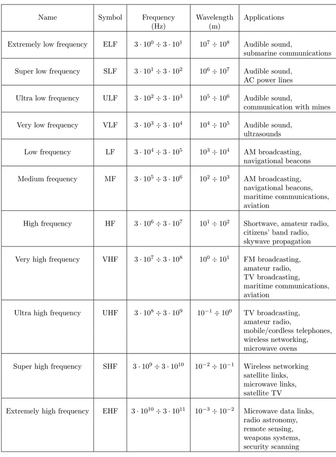
Since the radio spectrum is very wide, it is subdivided into frequency ranges, as shown in Table 1.1, which have specific properties and are used for different applications.
Radio frequency is one of the most popular mediums for telecommunications. Infor-mation in radio waves is transmitted by modulating a carrier signal of higher frequency (usually in the range of MHz or GHz) with a particular modulation.
Receivers extract information from these waves using the reverse operation of the modu-lation, the demodulation. Audio, video or data, in both analog and digital forms, can be used as a modulating signal. In the traditional radio approach, the modulation process is done by a chain of hardware components (oscillators, mixers, etc).
This approach has some limitations: the most important is the low flexibility to adapt to new services and standards.
Name Symbol Frequency Wavelength Applications
(Hz) (m)
Extremely low frequency ELF 3 · 100÷ 3 · 101 107÷ 108 Audible sound,
submarine communications Super low frequency SLF 3 · 101÷ 3 · 102 106÷ 107 Audible sound,
AC power lines Ultra low frequency ULF 3 · 102÷ 3 · 103 105÷ 106 Audible sound,
communication with mines Very low frequency VLF 3 · 103÷ 3 · 104 104÷ 105 Audible sound,
ultrasounds Low frequency LF 3 · 104÷ 3 · 105 103÷ 104 AM broadcasting,
navigational beacons Medium frequency MF 3 · 105÷ 3 · 106 102÷ 103 AM broadcasting,
navigational beacons, maritime communications, aviation
High frequency HF 3 · 106÷ 3 · 107 101÷ 102 Shortwave, amateur radio, citizens’ band radio, skywave propagation Very high frequency VHF 3 · 107÷ 3 · 108 100÷ 101 FM broadcasting,
amateur radio, TV broadcasting,
maritime communications, aviation
Ultra high frequency UHF 3 · 108÷ 3 · 109 10−1÷ 100 TV broadcasting, amateur radio,
mobile/cordless telephones, wireless networking, microwave ovens Super high frequency SHF 3 · 109÷ 3 · 1010 10−2÷ 10−1 Wireless networking
satellite links, microwave links, satellite TV
Extremely high frequency EHF 3 · 1010÷ 3 · 1011 10−3÷ 10−2 Microwave data links, radio astronomy, remote sensing, weapons systems, security scanning
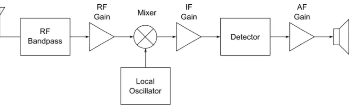
Figure 1.1: Block diagram of a traditional radio receiver
Each hardware element in radio chain (see Figure 1.1) performs a specific function. These components are designed to operate in a particular frequency band (RF) and stan-dard. When frequency or any of the parameters of a standard changes, traditional radios cannot correctly decode the information. Before being able to operate under the new conditions, the system must be redesigned and hardware modules have to be replaced. Since redesigning, manufacturing and replacing hardware components imply higher costs and longer time to market, traditional radios suffer longer time to market and higher costs for the development and manufacturing of new products.
1.2
The software approach
Contrary to traditional radio technology, SDR follows an approach that could remove drawbacks of current radios and also add new values, for example the cognitive radio con-cept (not part of this thesis).
Software pieces, and not hardware components, treat the signals to extract the informa-tion. The idea behind software-defined radio is to do the modulation and demodulation functions with software instead of using dedicated circuitry.
The most obvious benefit is that instead of having to build extra circuitry to handle dif-ferent types of radio signals, you can just load an appropriate software (or firmware). Following this principle, a common computer can be turned to an AM radio receiver or a wireless data transceiver or a digital HDTV receiver or furthermore to everything
men-tioned before at the same moment. Because of this, software defined radios are not limited in the number of services they can provide.
This flexibility of software could be exploited to do things that are difficult, if not impos-sible, with traditional radio setups. Some of them will be illustrated in this thesis. The method of extracting information in software requires the received signal to be trans-formed into the digital domain for processing (i.e. A/D Conversion), in contrast the transmit path does the opposite (i.e. D/A Conversion) while sending the signal to the antenna.
All the transceiving functions are performed by digital circuitry under software control. Software radios use digital signal processing (DSP) for filtering, modulation and demod-ulation of signals within the radio. While DSP can do everything an analog radio can do, it can also do functions that are difficult or impossible for analog radios. But more im-portantly, software radios are related to the computer software revolution that is affecting our society.
1.3
SDR architectures
To understand how SDR works, it is necessary to recall some principles (from [9]). Sampling or digitization is the process of converting an analog signal (a function of con-tinuous time) into a numeric sequence (a function of discrete time).
This process is done in accordance with the Nyquist Criterion, which states:
Exact reconstruction of a continuous-time baseband signal from its samples is possible if the signal is bandlimited and the sampling frequency is greater than twice the signal bandwidth.
Then the condition for exact reconstructability from samples at a uniform sampling rate in samples per unit time is: F s > 2B
In some cases this condition is intentionally not respected to produce the aliasing effect, that normally is harmful.
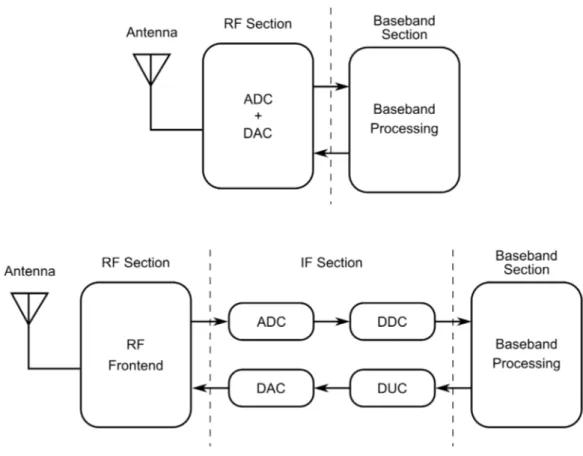
Now we can analyze diagrams in Figure 1.2.
Traditional radios use no digitization or baseband digitization. In ideal SDR archi-tecture, the digitization happens just after the antenna.
This is the best approach, since it allows processing the signal fully in software, but this kind of digitization is currently impossible to implement due to the state-of-the-art of analog-digital converters (ADC) and the limitations on computational capacity of con-temporary processors.
Once digitized, the signal is manipulated with signal processing techniques to extract the information. In this manner, A/D converters, general purpose processors and signal pro-cessing software replace the whole hardware based radio chain.
This approach is highly flexible and ideal because the same piece of equipment may be used for any new frequency, standard and application with simple software upgrades but is limited by the present state of the art of A/D converters and the limitations on com-putational capacity of present processors.
antenna, sampling is done over signals with very different strengths: the dynamic range of the signals may vary from µV to V . Current ADC resolutions are not able to cover such dynamic ranges. Nevertheless, significant research efforts are taking place to surmount this A/D converters exhibit higher power consumption than slower ones. If power con-sumption is very high, the A/D converter could dissipate too much heat and overheat the device. This issue is particularly critical in mobile devices, where cooling systems cannot be installed and the battery life is an extremely limiting factor. In fact, for mobile devices, the ADC power consumption should be within the range of 50 to 150 mW.
Currently, there are two trends in the A/D research. Some researchers direct their efforts to achieve high speeds, others focus on reducing the power consumption.
Another problem concerns computational capacity. When placing an A/D right after the antenna, the converter will be required to digitize the whole band, for instance from base-band to one (or more) GHz.
Such wideband receivers are still not a viable option for cost effective solutions. Also, the software must filter the samples to select the targeted signals. Such filtering has enormous computational cost that, today, can be only achieved using multiple processors.
To surmount the present problems of RF digitization we can chose a different point where to take the signal to digitize. Like in the traditional radio, we can exploit the con-version to intermediate frequency (IF).
A limited bandwidth of initial spectrum can be acquired, but we can freely chose a con-venient IF to match ADC limits. This is the base of actual SDR implementations. This design requires an RF front-end, which consists of a RF filter, a RF/IF converter and an IF filter. Subsequently the A/D converter digitizes the signal. The sampling frequency can be greater than required rate and can be adjusted later with a digital downconverter (DDC). The same applies to the transmission line with a digital upconverter (DUC). Then, the digital baseband signal can be processed with whatever processor and software. There are two main advantages of this configuration. Firstly, current A/D converters can achieve enough speed and resolution at IF frequencies. Secondly, this design requires less computational resources because the tunable RF filter of the front-end limits the number of received channels and thus the actual sample rate.
1.4
GNU Radio project
From project site ([4]):
GNU Radio is a free software development toolkit that provides the signal processing runtime and processing blocks to implement software radios using readily-available, low-cost external RF hardware and commodity processors. It is widely used in hobbyist, academic and commercial environments to sup-port wireless communications research as well as to implement real-world radio systems.
Founded by Eric Blossom, GNU Radio wants to allow an easy building of modula-tion, demodulamodula-tion, or more complex signal processing systems through the combination of signal processing blocks.
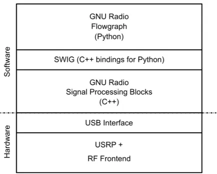
The core of GNU Radio is composed of a set of signal processing primitives written in C++. Furthermore, by using SWIG, an interface compiler which allows an easy integra-tion of C/C++ into scripting languages, GNU Radio provides a simple interface to the signal processing blocks from Python. Thus, the power of scripting languages is used to simply connect the signal processing blocks which can run at native speed without any interpretation. A detailed explanation about available blocks is present in Section 1.4.3.
1.4.1 Applications
GNU Radio was initially adopted by amateur radio enthusiasts, but the popularity of the open-source hardware/software has stretched the interest to universities as well.
Today, several applications are already written with GNU Radio. For example (from [12]), there are applications which decode HDTV pictures, which can receive and send AM/FM broadcast radio, and there is support for some simple modulation schemas like AM/FM/PSK.
system is, that GNU Radio doesn’t have a good support for packet based processing since it is stream oriented.
A DARPA project called “Adaptive Distributed Radio Open-source Intelligent Network (ADROIT)” attempts to change this by implementing a new primitive into GNU Radio, called the “M-block”. This will allow a simpler implementation of block based processing and it will also allow to annotate data with meta data.
Here is a list of published applications. Most of these works derive from the use of the USRP board (described at page 17).
A complete GPS receiver has been implemented with the DBSRX daughterboard. It receives GPS signals, and contains interfaces to the Google Earth data. Eric Blossom presented a passive radar by using FM frequencies and exploiting the MIMO capabilities of the USRP.
A DVB module ([10]) with a full software implementation is capable of transmitting DVB-T compliant signals in realtime. DVB-The corresponding receiver part is in development. Part of a DAB receiver has also been implemented, including a working physical layer, part of Fast Information Channel (FIC) to see the names of the radio stations, but without the Main Service Channel (required to actually hear something).
Wiser S.r.l. is working on a GSM-R Signal Integrity Detection System that should be available soon.
Implementations for IEEE 802.11, Bluetooth, IEEE 802.15.4, and GSM are also available with certain limitations because of USB 2.0 bandwidth, but should be resolved with the new USRP 2 interface.
1.4.2 Flowgraphs
With GNU Radio is simple to build an FM receiver just creating a graph where the nodes are signal processing blocks and the edges represent the data flow between them.
The graph, called “flowgraph”, is a group of signal processing blocks that are connected together to reach a target that is usually a communications system.
layers that makes the user create its own project transparently to the implementation. Everything concerns a flowgraph is written in Python programming language. A primary Python thread has the goal of initializing blocks and handling runtime parameter mod-ifications to the flow graph (e.g. multiplier, squelch level, etc.). Any information (i.e. samples or bits) passing through a flow graph block is managed in a separate thread, the signal processing thread.
In order to start the flow graph, each of the blocks must be connected together using the input and output ports of the flow graph block. The first block in the flow graph is called the source block and only contains output connections. The source block can be a sine wave, a set of samples stored in a file, a vector, or the USRP (for receiving), etc. The last block in the flow graph is called the sink block and only contains input connections. The sink block can be an output to a file, or a vector, or the USRP (for transmitting), etc. All other blocks contain both input and output connections. All the details can be read in the following section.
1.4.3 Blocks
Signal processing blocks are implemented in C++ exploiting some CPU optimized rou-tines, written in Assembler language, and other optimized libraries, like FFTW for Fourier transforms.
Conceptually, a signal processing block processes an infinite stream of data flowing from its input ports to its output ports except special blocks, like sources and sinks, that have only one port. Block attributes include the number of input and output ports it has as well as the type of data that flows through each.
More than 100 blocks are currently implemented in GNU Radio. A summary is reported below:
• Sources (signal, noise, vector, random, null, file, udp, audio, wav, pad) • Sinks (vector, null, file, udp, audio, wav, pad )
• Graphical sinks (number, scope, fft, constellation, waterfall)
• Operators (arithmetic ops, logic ops, fft, max, rms, integrate, conjugate) • Type conversion (complex, float, [i]short, [u]char, mag, square mag, real, imag) • Stream conversion ([de]interleave, stream to streams, vector to stream[s]) • Synchronizers (clock recovery, pll, correlator, psk sync, packet [en,de]coder) • Level controls (peak detector, agc, mute, squelch, threshold, sample and hold) • Filters (lp, hp, bp, br, fft, iir, hilbert, goertzel, resampler, decim, interp) • Modulators (vco, [wb,nb]fm, pm, fsk, quad demod, constellation, gmsk, qam) • USRP (source, sink, dual source, dual sink)
• Variables (variable, slider, chooser, text box, sink, parameter)
1.4.4 GRC
Programming applications with GNU Radio toolkit has some drawbacks. “Toolkit” means a set of libraries and programs that offers a quite simple interface to complex functions. Before GRC, that is now part of the toolkit, the program writing was difficult due to the steep learning curve of GNU Radio. With no graphical helpers, to generate a flowgraph, a user had to learn how to write looking to other programmers’ work. Since everything is command line based, and the library is very large, the learning period prior to have a result was quite long.
To aid beginners, Josh Blum has developed a graphical interface for GNU Radio. This GUI, named GNU Radio Companion (GRC), allows users to interact with GNU Radio signal blocks in a manner similar to Labview or Simulink (see Figure 1.5).
The entire interface is completely designed with GNU Radio in mind, and encompasses over 150 blocks from the GNU Radio Project. New blocks can be integrated into GRC via descriptive Python definitions. The definitions are very flexible, and allow multiple GNU Radio blocks to be grouped into a single GRC super-block.
GRC quickly realizes what you have in mind. Just selecting some block and con-necting them together with some clicks and the flowgraph is ready. After adding some processing blocks, represented as rectangles, the working space can be a little crowded and connecting lines can be overlap themselves.
The working space can be sized up to 2048 x 2048 pixels.
To restore a better environment, blocks can be manually reorganized, moved and rotated. With the mouse is also possible to change the properties for each block with a double-click. When handling the signal routing between blocks, the interface aids the user denying or highlighting wrong choices (i.e. the user connects blocks with different that accepts un-matching types of data).
Only when the graph is consistent, from source to sink, the GUI allows to create a Python file with the flowgraph.
The graph validation occurs by following these steps:
• Connections are made between input and output sockets of the same data type. Different data types have different colors. Therefore, input and output colors must match. Invalid connections are highlighted red.
• All sockets must be connected (except for the optional sockets). Disconnected sockets cause their signal block to have a red label.
• All signal block parameters must be valid. For instance, numerical expressions can be parsed. Invalid parameters have red labels and cause their signal block to have a red label.
GRC is also able to directly run (and stop) created programs. Both command line programs, Wx windowed programs and hier blocks can be created.
1.5
Universal Software Radio Peripheral
The Universal Software Radio Peripheral (USRP) is a device, linked with GNU Radio, which allows the creation of a software defined radio. A USB 2.0 port allows its easy integration to a normal PC. Various plug-on daughterboards allow the USRP to be used on different radio frequency bands. Presently, daughterboards operating from DC to almost 5.9 GHz are available ([2]). The entire schematics design of the USRP is open source. A typical setup of the USRP board consists of one mother board and up to four daughter boards.
1.5.1 A valuable device
One USRP can simultaneously receive and transmit on two antennas in real time. All sampling clocks and local oscillators are fully coherent, thus allowing the creation of MIMO (multiple input, multiple output) systems. In the USRP, high sampling rate processing takes place in the FPGA, while lower sampling rate processing occurs at the host computer. The two onboard digital downconverters (DDCs) mix, filter, and decimate (from 64MS/s) incoming signals in the FPGA. Two digital upconverters (DUCs) interpolate baseband signals to 128 MS/s before translating them to the selected output frequency. The DDCs and DUCs combined with the high sampling rates also greatly simplify analog filtering requirements. Daughterboards mounted on the USRP provide flexible, fully integrated RF front-ends. The USRP accommodates up to two RF transceiver daughterboards (or two transmit and two receive) for RF I/O.
At the moment, there is nothing comparable to the USRP in the market. Its price is very competitive among high-end devices, and its performance is superior to other common implementations.
Of course, this board has some limitations, that will be described further, thus a new model, USRP 2, with major improvements is near to be commercialized.
1.5.2 Hardware components
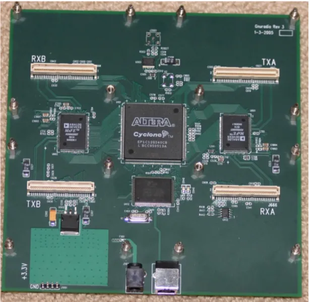
The USRP consists of a motherboard containing four ADCs, four DACs, a million gate Field Programmable Gate Array (FPGA) and a programmable USB 2.0 controller. Each component on the board is fully documented, allowing the owners to modify or add frontends to address every need.
Subsequently, a detailed description explains hardware and software properties.
Cypress USB controller
From CY7C68013’s datasheet:
Cypress’s EZ-USB FX2R TM is the world’s first USB 2.0 integrated
microcon-troller. By integrating the USB 2.0 transceiver, SIE, enhanced 8051 micro-controller, and a programmable peripheral interface in a single chip, Cypress has created a very cost effective solution that provides superior time-to-market advantages.
The ingenious architecture of FX2 results in data transfer rates of 56 MByte/s, the maximum allowable USB 2.0 bandwidth, while still using a low-cost 8051 microcontroller in a package as small as a 56 SSOP. Because it incorporates the USB 2.0 transceiver, the FX2 is more economical, providing a smaller foot-print solution than USB 2.0 SIE or external transceiver implementations. With EZ-USB FX2, the Cypress Smart SIE handles most of the USB 1.1 and 2.0 protocol in hardware, freeing the embedded microcontroller for application-specific functions and decreasing development time to ensure USB compatibil-ity. The General Programmable Interface (GPIF) and Master/Slave Endpoint FIFO (8- or 16-bit data bus) provides an easy and glueless interface to popular interfaces such as ATA, UTOPIA, EPP, PCMCIA, and most DSP/processors.
In other words, it is a high-speed USB peripheral controller that allows to initialize the FPGA (loading firmware) and further data transfer from/to the ADC/DACs. It is handled with a Python user space driver that communicates via 3 USB endpoints, 1 for commands and 2 (in bulk mode) for sample in/out.
Cyclone FPGA
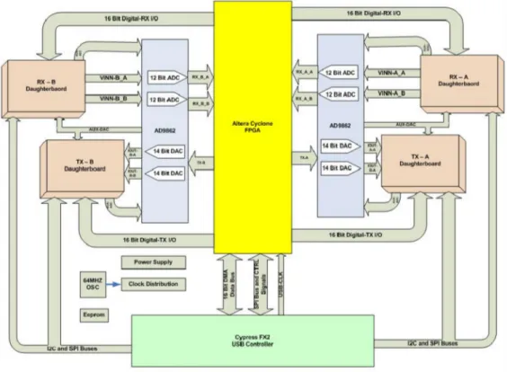
The core of the USRP is an Altera FPGA, more exacly a Cyclone EP1C12Q240C8. Understanding the FPGA operation is one of the important steps for GNU Radio users. As shown on Figure 1.8, all the ADCs and DACs are connected to the FPGA. The FPGA plays a key role in the GNU Radio system. Basically what the FPGA does is to perform high bandwidth math, and to reduce the data rates to something that can be easily transferred over a USB 2.0 interface. The FPGA connects to an USB 2.0 interface chip, the Cypress FX2. Everything (FPGA circuitry and USB 2.0 Microcontroller) is programmable over the USB 2.0 bus.
The standard FPGA configuration (firmware) includes digital down converters (DDC) implemented with cascaded integrator-comb (CIC) filters. CIC filters are very high-performance filters using only adds and delays. The FPGA implements 4 digital down converters (DDC), which allows 1, 2 or 4 separate RX channels. At the RX path, there are 4 ADCs and 4 DDCs. Each DDC has two inputs I and Q. Each of the 4 ADCs can be routed to either the I or the Q input of any of the 4 DDCs, which allows for having multiple channels selected out of the same ADC sample stream.
The digital up converters (DUCs) on the transmit side are actually contained in the AD9862 CODEC chips, not in the FPGA. The only transmit signal processing blocks in the FPGA are the interpolators. The interpolate outputs can be routed to any of the 4 CODEC inputs.
The multiple RX channels must all be the same data rate. The same applies to the TX channels, where each channel must be at the same data rate, which may be different from the RX rate.
The digital down converter (DDC), first, down converts the signal from the IF band to the base band. Second, it decimates the signal so that the data rate can be adapted by the USB 2.0 and is reasonable for the computers’ computing capability. The complex input signal (IF) is multiplied by the constant frequency (usually also IF) exponential signal.
The resulting signal is also complex and centered at 0. Then the signal is decimated with a factor of N.
The decimator can be treated as a low pass filter followed by a downsampler. Con-sider the decimation factor to be D. The digital spectrum, the low pass filter selects the band [-p/D, p/D], and the downsampler spreads the spectrum in [-p/D, p/D] to [-p, p]. Thus, the bandwidth of the digital signal of interest is narrowed down by a factor of D. The USB 2.0 interface can sustain about 32 MByte/s across it. All samples sent over the USB 2.0 interface are in 16-bit signed integers in IQ format, i.e. 16-bit I and 16-bit Q data (complex), resulting in 8 MS/s (complex) across the USB 2.0.
This provides a maximum effective total spectral bandwidth of about 8 MHz by Nyquist criteria. Of course a much narrower range can be selected by changing the decimation rate.
For example, the bandwidth of a FM station is generally 200 kHz. Therefore the deci-mation factor can be set to 250, then the data rate across the USB 2.0 is 64 MHz / 250 = 256 kHz, which is well suited for the 200 kHz bandwidth without losing any spectral information.
The IF frequency of the DDC can be set using usrp.set rx freq() method and the decima-tion factor can be set using the usrp.set decim rate() method in Python. The decimadecima-tion rate must be in the range [1,256].
Note that when there are multiple channels (up to 4), the channels are interleaved. For example, with 4 channels, the sequence sent over the USB 2.0 interface would be I0 Q0 I1 Q1 I2 Q2 I3 Q3 I0 Q0 I1 Q1, etc.
The MUX is like a router or a circuit switch. It determines which ADC (or a zero constant) is connected to each DDC input. As shown on Figure 1.7, there are 4 DDCs, each having two inputs. The MUX is controlled with Python.
Each input specified with (I0, Q0, I1 ... I3, Q3), i.e denoting which ADC is connected to it by using 4 bits (0, 1, 2, 3 or 0xf). Therefore a 32-bit integer would be enough for all 8 inputs to know which ADC is connected.
Figure 1.7: Flow multiplexing in the USRP
the set mux() method. For most real sampling applications, the Q input of each DDC is constant zero. So quite often the modification of standard configuration of the FPGA is not required.
The USRP can operate in full duplex mode. When in duplex mode, the transmit and the receive sides are completely independent of one another. The only consideration is that the combined data rate over the USB 2.0 bus must be 32 MByte/s or less.
Finally when the I/Q complex signal enters the computer via the USB 2.0 interface, that’s where the software takes over the processing.
At the TX path, the story is pretty much the same, except that it happens in inverse. A baseband I/Q complex signal needs to be sent to the USRP board from the computer. The digital up converter (DUC) interpolates the signal, up converts it to the IF band, and finally sends it through the DAC.
ADCs
The 4 high-speed 12-bit AD converters can sample at a rate of 64 MS/s. In theory, it could digitize a band as wide as 32 MHz.
The AD converters can bandpass-sample signals of up to about 150 MHz. If an IF signal larger than 32 MHz is sampled, it introduces aliasing. The higher the frequency of the
sampled signal, the more the SNR degrades by jitter. The recommended upper limit is 100 MHz.
The full range on the ADCs is 2V peak-to-peak, and the input is 50 Ohms differential, i.e 40 mW, or 16 dBm.
A programmable gain amplifier (PGA) is used before the ADCs to amplify the input signal, and to utilize the entire input range of the ADCs, in case the signal is weak. The PGA range is up to 20dB.
Other sampling rates can be used if needed. The available rates are all submultiples of 128, such as 64, 32 etc. In principle, the 4 input and 4 output channels use real samplings. However, there will be more flexibility (and bandwidth) if a complex (I/Q) sampling is used. For instance, the input and output channels can be paired up, resulting in 2 complex inputs and 2 complex outputs.
DACs
At the transmitting path, there are 4 high-speed 14-bit DA converters. The DAC clock frequency is 128 MHz, thus Nyquist frequency is 64 MHz. Staying below 50 MHz or so is suggested to make filtering easier, therefore the useful output frequency range is DC to about 50 MHz.
The DACs can supply a peak output of 1 V, or 10 mW (10 dBm), to a 50 Ohm differential load.
Similarly to the RX path, in the TX path there is programmable-gain amplifier that provides up to 20 dB gain to the DAC output.
Analog and digital I/O
There are 8 Auxiliary analog input channels connected to low speed 10 bit ADC inputs which can be read from software. These ADCs can convert up to 1.25 MS/s and have a bandwidth of around 200 kHz. These analog channels are useful for sensing the RSSI signal levels, temperatures, bias levels, etc.
Additionally, there are 8 analog output channels connected low-speed 8bit DAC outputs. These DACs can be used for supplying various control voltages such as external variable gain amplifiers control. Moreover, there are two additional DACs which are constructed using 12 bit sigma-delta modulator with external simple low pass filter. The USRP motherboard connectors share one set of the 4 analog output channels and each have 2 independent analog input channels. The RXB and TXB share their other own independent set. There is also AUX ADC REF which can provides a reference level for gain setting if it is necessary.
The USRP motherboard has also high speed 64 bit digital I/O ports. These are divided in two groups (32 bit for IO RX and 32 bit for IO TX). These digital I/O pins are connected to the daughterboards interface connectors. Each of these connectors has 16 bit digital I/O bits.
ters and each can be independently configured either as digital input or digital output. Some of these pins are used to control specific operations on the installed daughterboards such as controlling the selection of receiving RF input port, in automatic transmit/receive mode, controlling power supply feeding for different TX and RX parts, synthesizer lock detection, etc. It can be also used to implement AGC processing and can be very helpful in debugging FPGA implementations when connected to a logic analyzer.
Figure 1.9: USRP enclosure: daughterboards connectors replicated on front panel.
Daughterboards
The daughterboards are used to hold an RF receiver interface or an RF transmitter or both. The USRP has 4 slots that can be used to plug in up to 2 RX daughterboards and 2 TX daughterboards.
The TX slots are labeled TXA and TXB, and the 2 corresponding RX slots RXA and RXB. Each daughterboard slot has access to 2 of the 4 high-speed AD/DA converters, this allows each daughterboard, which uses real (not I/Q) sampling, to have 2 independent RF sections (RX or TX) and 2 antennas (4 total for the system). If complex I/Q sampling is used, each board can support a single RF section, for a total of 2 for the whole system. Usually, on each daughterboard there are one or two SMA connectors that can be used to connect the input or output signals to the board. An exception is the TV-RX board, used for this thesis, that mounts an integrated TV tuner with F connector.
Here is a list of currently available daughterboards:
• BasicTX: Transmitter for use with external (user supplied) RF hardware • BasicRX: Receiver for use with external (user supplied) RF hardware • LFTX: DC-30 MHz Transmitter • LFRX: DC-30 MHz Receiver • TVRX: 50 MHz to 870 MHz Receiver • DBSRX: 800 MHz to 2.4 GHz Receiver • RFX400: 400 MHz - 500 MHz Transceiver, 100+mW output • RFX900: 800-1000MHz Transceiver, 200+mW output • RFX1200: 1150 MHz - 1450 MHz Transceiver, 200+mW output • RFX1800: 1.5-2.1 GHz Transceiver, 100+mW output • RFX2400: 2.3-2.9 GHz Transceiver, 20+mW output
• XCVR2450: 2.4-2.5 GHz and 4.9 to 5.85 GHz Dual-band Transceiver, 100+mW output on 2.4 GHz, 50+mW output on 5GHz
Chapter 2
Maritime Communications
An Italian engineer, Guglielmo Marconi, invented radio in 1895. The first use of radio, for communication over sea, succeeded on 3 March of 1899 when the East Goodwin Lightship which was anchored ten miles offshore from the south east coast of England required assistance. A distress call was transmitted by wireless to a shore station at South Foreland and help was dispatched. Since the invention of radio, ships at sea have relied on Morse code for maritime communications. Although telecommunications technology is improving quickly, people at sea do not have access to the same telecommunications infrastructure people ashore have.
Morse encoded distress calling saved thousands of lives since its inception almost a century ago, but its use requires skilled radio operators spending many hours listening to the radio distress frequency. Its range on the medium frequency (MF) distress band (500 kHz) is limited, and the amount of traffic Morse signals can carry is also limited.
Mariners, not only need to access international shore telephone and data public switched networks, but also, they need to be able to communicate with other ships of any size or nationality, to receive and send urgent maritime safety information, and to send or receive distress alerts in an emergency to or from rescue coordination centers ashore and nearby ships anywhere in the world.
Maritime telecommunications systems must be internationally interoperable, affordable, acceptable and available to most ships and maritime countries.
Over fifteen years ago the International Maritime Organization (IMO) ([3]), a United Nations agency specializing in safety of shipping and preventing ships from polluting the seas, began looking at ways of improving maritime distress and safety communications. In 1979, a group of experts drafted the International Convention on Maritime Search and Rescue, which called for development of a global search and rescue plan.
This group, in close co-operation with the International Telecommunication Union (ITU) and other international organizations, notably the World Meteorological Organization (WMO), the International Hydrographic Organization (IHO) and the COSPAS-SARSAT partners passed a resolution calling for development of a Global Maritime Distress and Safety System (GMDSS) to provide the communication support needed to implement the search and rescue plan. The main guideline of the IMO convention was solving the inad-equacy of existing distress and safety systems.
The subsequent development process enabled the shipping industry to put the new distress and safety system into use on 1 February 1 1992. The SOLAS (Safety Of Life At Sea) Convention introduced some stages between 1993 and 1 February 1999 to allow the migra-tion from old systems and the new GMDSS. On that last date, Morse wireless telegraphy, used since the beginning of the 20th century, discontinued worldwide.
The GMDSS creation is marked the biggest change to maritime communications since the invention of radio.
2.1
Global Maritime Distress and Safety System
The basic concept of GMDSS is that search and rescue authorities ashore, as well as ship-ping in the immediate vicinity of the ship in distress, will be rapidly alerted to a distress incident so that they can assist in a co-ordinated search and rescue operation with the minimum delay.
The system also provides for agency and safety communications and the promulgation of Maritime Safety Information (MSI): navigational and meteorological warnings and fore-casts and other urgent safety information to ships.
those communication functions which are essential for the safety of the ship itself and of other ships operating in the same area.
Major changes affects the users: before it, the communications were carried by radiotelegraphs with the need of a specialized operator; now the operator needs a certificate, GOC or ROC, released from the national organs that controls the sea traffic, that does not requires an advanced or specific knowledge to the operator, for instance the Morse code. Furthermore, automatic distress alerting and locating task become available also if the radio operator does not have time to send an SOS or MAYDAY call, and, for the first time, ships are re-quired to receive broadcasts of maritime safety information which could prevent a distress from happening in the first place ([6]).
The system is able to reliably perform the following functions: alerting (including position determination of the unit in distress), search and rescue coordination, locating (homing), maritime safety information broadcasts, general communications, and bridge-to-bridge communications. The system also provides redundant means of distress alerting, and emergency sources of power.
Specific radio carriage requirements depend upon the ship’s area of operation, rather than its tonnage. Under IMO legislation, all passenger vessels and all other vessels over 300 GRT had to be fitted with the necessary equipment. By 1 August 1993, all these ships are required to be equipped with satellite emergency position-indicating radiobeacons (EPIRBs) and NAVTEX receivers, to automatically receive shipping safety information. The required onboard equipment depends also on the area of operation as described in the following section.
2.2
Sea areas
GMDSS sea areas serve two purposes: to describe areas where GMDSS services are avail-able, and to define what GMDSS ships must carry. Prior to the GMDSS, the number and type of radio safety equipment ships had to carry depended upon its tonnage. With GMDSS, the number and type of radio safety equipment ships have to carry depend upon the areas in which they travel. GMDSS sea areas are defined by governments.
Specific equipment requirements for ships vary according to the sea area in which the ship operates. The GMDSS combines various subsystems - which all have different limitations with respect to coverage - into one overall system, and the oceans are divided into four sea areas:
• Area A1: Within range of VHF coast stations with continuous DSC (2187.5 kHz) alerting available (about 20-30 miles).
• Area A2: Beyond area Al, but within range of MF coastal stations with contin-uous DSC alerting available (about 100 miles). GMDSS-regulated ships travelling this area must carry a DSC-equipped MF radiotelephone in addition to equipment required for Area A1.
• Area A3: Beyond the first two areas, but within coverage of geostationary maritime communication satellites (Inmarsat). This covers the area between roughly 70 deg N and 70 deg S. Ships travelling this area must carry either an Inmarsat F77, B or C ship earth station, or a DSC-equipped HF radiotelephone/telex, in addition to equipment required for an A1 and A2 Area.
• Area A4: The remaining sea areas. The most important of these is the sea around the North Pole (the area around the South Pole is mostly land). Geostationary satellites, which are positioned above the equator, cannot reach this far. Ships travelling these polar regions must carry a DSC-equipped HF radiotelephone/telex, in addition to equipment required for areas A1 and A2.
In addition to previously listed equipments, all GMDSS-regulated ships must carry a satellite EPIRB, a NAVTEX receiver (if they travel in any areas served by NAVTEX), an Inmarsat-C SafetyNET receiver (if they travel in any areas not served by NAVTEX), a DSC-equipped VHF radiotelephone, two or more VHF handhelds, and a search and rescue radar transponder (SART).
2.3
NAVTEX
NAVTEX is an international, automated system for instantly distributing maritime navi-gational warnings, weather forecasts and warnings, search and rescue notices and similar information to ships.
The NAVTEX system is designed to be used in GMDSS Sea Area A2, and is utilized mainly by those countries with relatively small areas of coastline and/or sea areas to cover. System range is generally 300 or so nautical miles from the transmitter.
Major areas of NAVTEX coverage include the Mediterranean Sea, the North Sea, coastal areas around Japan and areas around the North American continent.
The system mainly operates in the Medium Frequency radio band just above and below the old 500 kHz Morse Distress frequency. Three broadcast frequencies has been allocated for NAVTEX:
• 518 kHz - the main NAVTEX channel
• 490 kHz - used for broadcasts in local languages (i.e. non-English)
• 4209.5 kHz - allocated for NAVTEX broadcasts in tropical areas - not widely used at the moment.
All broadcasts from stations within the same NAVAREA must be coordinated on a time sharing basis to eliminate interference. In addition, power outputs from each station are adjusted to control the range of each broadcast. This is particularly important during night-time hours, as medium frequencies always have a large propagation.
All messages are received by a printing radio receiver (Figure 2.1), installed in the pilot house of a ship or boat, that checks each incoming message to see if it has been received during an earlier transmission. Messages can be filtered on a category base depending on the ship’s master interest.
Figure 2.1: NAVTEX direct printing
2.4
COSPAS-SARSAT and EPIRBs
COSPAS-SARSAT is an international satellite-based search and rescue system, established by Canada, France, the U.S.A., and Russia. These four countries jointly helped develop a 406 MHz satellite emergency position-indicating radiobeacon (EPIRB), an element of the GMDSS designed to operate with COSPAS-SARSAT system.
These automatic-activating EPIRBs, now required on SOLAS ships, commercial fishing vessels, and other ships, are designed to transmit to a rescue coordination center a vessel identification and an accurate location of the vessel from anywhere in the world.
There are three types of distress radio beacons compatible with the system:
• EPIRBs (emergency position-indicating radio beacons) signal maritime distress. • ELTs (emergency locator transmitters) signal aircraft distress.
• PLBs (personal locator beacons) are for personal use and are intended to indicate a person in distress who is away from normal emergency services.
Figure 2.2: COSPAS-SARSAT operation schema and a GPS equipped EPIRB
Most beacons are brightly colored and waterproof. EPIRBs and ELTs are larger, and would fit in a cube about 30 cm on a side, and weigh 2 to 5 Kg (an example of EPIRB is shown on Figure 2.2). PLBs vary in size from cigarette-packet to paperback book and weigh 200 g to 1 Kg.
The EPIRB units can be purchased from marine suppliers or aircraft refitters and have a useful life of 10 years. Every unit is programmed with a unique identifier and registered to national coast guard service.
The frequencies of operation are:
• 121.5 MHz ± 6 kHz (frequency band protected to ± 50 kHz) • 243.0 MHz ± 12 kHz (frequency band protected to ± 100 kHz) • 406 MHz - carrier wave at 406.025 MHz ± 0.005 MHz
The 121.5 and 243 MHz are the most common and least expensive type of EPIRB, designed to be detected by overflying commercial or military aircraft. Satellites were de-signed to detect these EPIRBs, but are limited.
Instead, the 406 MHz EPIRB was designed to operate with satellites. The signaling frequency has been designated internationally for use only for distress. Other communica-tions and interference, such as on 121.5 MHz, is not allowed on this frequency. Its signal allows a satellite local user terminal to accurately locate the EPIRB and identify the vessel anywhere in the world (there is no range limitation).
2.5
SARTs
Figure 2.3: An installed radar SART
SARTs are self contained, portable and buoyant radar transponders typically cylin-drical, and brightly colored (see Figure 2.3).
These systems are designed to guide rescuers to your location. SARTs operate in the 9 GHz marine radar band, and when interrogated by a searching ship’s radar, respond with a signal which is displayed on a radar screen: a line of 12 dots, where each dot corresponds to 0.6 nautical miles, extending outward from the SARTs position along its line of bearing. As the searching vessel approaches the SART, the radar display will change to wide arcs. These may eventually change to complete circles as the SART becomes continually trig-gered by the searching ship’s radar. Some slight position error will also be caused by the SART switching from receive to transmit mode.
searching radar. The range achievable from a SART is directly proportional to its height above the water. A SART mounted at 1 m (i.e. in a liferaft) should be able to be detected at 5 nautical miles by a ship’s radar mounted at 15 m. The same SART should be able to be detected at 30 nautical miles by an aircraft flying at 8000 feet.
GMDSS vessels from 300 to 500 GRT are required to carry 1 SART, and vessels over 500 GRT are required to carry 2.
In the future, from 2010, AIS-SARTs, instead of radar-SARTs, will be available. AIS-SARTs will be used, similarly to radar ones, to locate a survival craft or distressed vessel. The AIS-SART derives and transmit its position and get time synchronization from a built in GNSS receiver. Every minute the position is sent as a series of equal position reports, this is to maintain a high probability that at least one of the position reports is sent on the highest point of a wave. The specification for the AIS-SART is currently being developed by the AIS work group in IEC, TC80.
Figure 2.4: An AIS-SART
2.6
Inmarsat
The International Mobile Satellite Organization (Inmarsat), previously the International Maritime Satellite Organization, was established by IMO in 1976 to operate satellite mar-itime communication systems and has become a privately owned company, while retaining its public sector obligations to the maritime distress and safety system.
Figure 2.5: Inmarsat satellites coverage
Three types of Inmarsat terminals are recognized by the GMDSS: A, B and C. The Inmarsat A and B provide ship/shore, ship/ship and shore/ship telephone, telex and high-speed data services, including a distress priority telephone and telex service to and from rescue coordination centers.
The Inmarsat C provides ship/shore, shore/ship and ship/ship store-and-forward data and telex messaging, the capability for sending preformatted distress messages to a rescue coordination center, and the SafetyNET service. Inmarsat C equipment is relatively small and lightweight, and costs much less than an Inmarsat B.
The SafetyNET service is a satellite-based worldwide maritime safety information broad-cast service of high seas weather warnings, navigational warnings, radionavigation warn-ings, ice reports and warnings generated by the International Ice Patrol, and other similar information not provided by NAVTEX. SafetyNET works similarly to NAVTEX in areas outside NAVTEX coverage.
SOLAS now requires that Inmarsat C equipment have an integral satellite navigation re-ceiver, or be externally connected to a satellite navigation receiver. That connection will ensure accurate location information to be sent to a rescue coordination center if a distress alert is ever transmitted.
2.7
Radiotelephones (MF/HF/VHF)
Radiotelephone systems allows ship/ship or ship/shore wireless communication. They are similar to telephones but usually simplex (half-duplex) instead of duplex. This is because a duplex system would require a radio system to simultaneously transmit and receive on two separate channels, which both wastes bandwidth and presents some technical challenges. Simplex frequency operation allows one person to talk and the other to listen alternately. Another common way to communicate is the dual-frequency simplex: the communication splits into two separate channels, but only one is used to transmit at a time.
Normally, the user presses a special switch on the transmitter when he wish to talk. For this reason, the button is called the “push-to-talk” switch or PTT. Usually it is fitted on the side of the microphone or other obvious position. Users may use a special code-word such as “over” to signal that they have finished transmitting, or it may follow from the conversation.
Radiotelephones operates on different frequencies with different modulations. Com-mon maritime channels are present at 2, 4, 6, 8, 12, 16, 18, 22 and 25 MHz for MF/HF, and near 160 MHz for VHF.
VHF Channel 16 (156.8 MHz) is monitored 24 hours a day by coastguards around the world. In addition, all sea bound vessels are required to monitor channel 16 VHF when sailing, except when communicating on other marine channels for legitimate business or operational reasons.
Coastguards and others are permitted to broadcast short informative safety messages on channel 16, however, it is an offense in most countries to make false ”Mayday” calls or broadcast on channel 16 unless in distress.
On MF, 2182 kHz channel is analogous to VHF channel 16, but unlike VHF which is limited to about 50 nautical miles (90 km) range, communications on 2182 kHz (and nearby frequencies) have a typical range of around 150 nautical miles (280 km) during the day and 500 (or more) nautical miles at night.
On MF/HF channels, single-sideband (SSB) modulation is used. This because the short wave bands are crowded with many users, and SSB permits a single voice channel to use a narrower range of radio frequencies (bandwidth) than AM or FM.
On VHF, instead, the frequency modulation is used. This allows transmitted signal to be more robust against noise and interference.
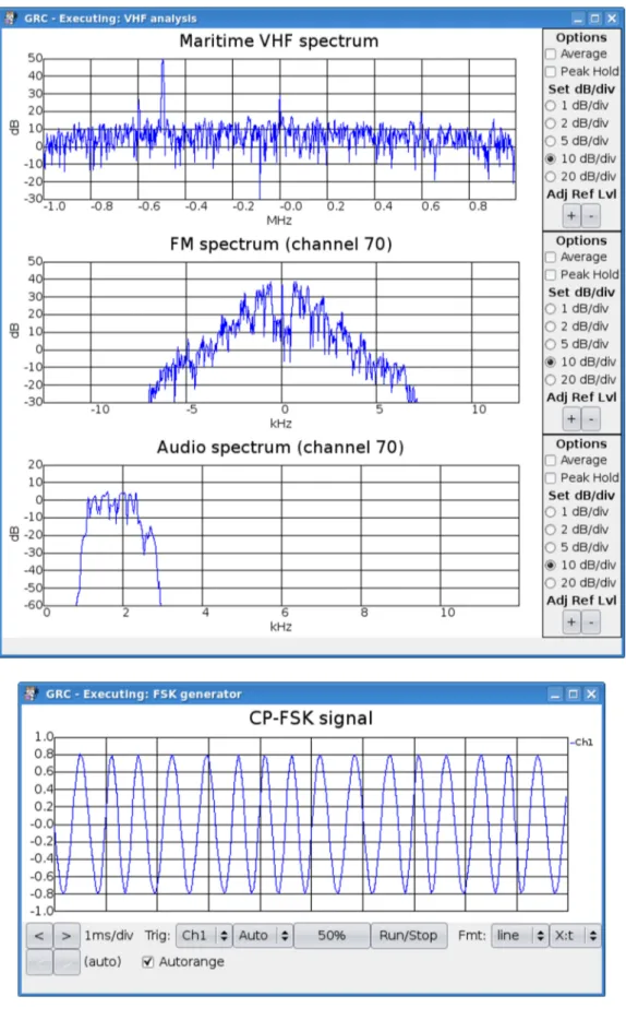
Here are some more accurate technical specifications of maritime VHF:
• Allowed frequencies are from 156.000 to 162.500 with 25 kHz channelization. Channels are numbered from 1 to 28 and from 60 to 88 (see Table 2.1 for details). • Modulations used are: G3E or F3E for voice channels and G2B or F1B for DSC. • Maximum frequency deviation (for FM) is 5 kHz. Modulation index is 5/3. • Audio signal (modulating signal) must be limited to 3 kHz.
• Pre-emphasis and de-emphasis starting at 300 Hz with 6 dB/octave filters. • Authorized nominal bandwidth is 16 kHz for voice channels and 20 kHz for data. • Power: coast stations 100 W, ship stations 6 to 25 W (50 W if it can be remotely
reduced by coast stations) and 5 W for handhelds.
An example of VHF-DSC ship radiotelephone, is shown on subsequent pictures. This apparatus, kindly supplied by Elman S.r.l., is fully compatible with VHF-DSC stan-dard and has been used for testing the DSC functionalities of the monitoring system.
Figure 2.6: Elman RTV-1077-D VHF-DSC transceiver (front panel)
Channel Ship TX Base TX Simplex Channel Ship TX Base TX Simplex
number (MHz) (MHz) Duplex number (MHz) (MHz) Duplex
1 156.050 160.650 D 60 156.025 160.625 D 1A 156.050 156.050 S 60A 156.025 156.025 S 2 156.100 160.700 D 61 156.075 160.675 D 2A 156.100 156.100 S 61A 156.075 156.075 S 3 156.150 160.750 D 62 156.125 160.725 D 3A 156.150 156.150 S 62A 156.125 156.125 S 4 156.200 160.800 D 63 156.175 160.775 D 4A 156.200 156.200 S 63A 156.175 156.175 S 5 156.250 160.850 D 64 156.225 160.825 D 5A 156.250 156.250 S 64A 156.225 156.225 S 6 156.300 160.900 D 65 156.275 160.875 D 6A 156.300 156.300 S 65A 156.275 156.275 S 7 156.350 160.950 D 66 156.325 160.925 D 7A 156.350 156.350 S 66A 156.325 156.325 S 8 156.400 156.400 S 67 156.375 156.375 S 9 156.450 156.450 S 68 156.425 156.425 S 10 156.500 156.500 S 69 156.475 156.475 S 11 156.550 156.550 S 70 156.525 156.525 S 12 156.600 156.600 S 71 156.575 156.575 S 13 156.650 156.650 S 72 156.625 156.625 S 14 156.700 156.700 S 73 156.675 156.675 S 15 156.750 156.750 S 74 156.725 156.725 S 16 156.800 156.800 S 75 156.775 156.775 S 17 156.850 156.850 S 76 156.825 156.825 S 18 156.900 161.500 D 77 156.875 161.475 D 18A 156.900 156.900 S 77A 156.875 156.875 S 19 156.950 161.550 D 78 156.925 161.525 D 19A 156.950 156.950 S 78A 156.925 156.925 S 20 157.000 161.600 D 79 156.975 161.575 D 20A 157.000 157.000 S 79A 156.975 156.975 S 21 157.050 161.650 D 80 157.025 161.625 D 21A 157.050 157.050 S 80A 157.025 157.025 S 22 157.100 161.700 D 81 157.075 161.675 D 22A 157.100 157.100 S 81A 157.075 157.075 S 23 157.150 161.750 D 82 157.125 161.725 D 23A 157.150 157.150 S 82A 157.125 157.125 S 24 157.250 161.850 D 83 157.175 161.775 D 25 157.300 161.900 D 83A 157.175 157.175 S 26 157.350 161.950 D 84 157.225 161.825 D 27 157.400 162.000 D 84A 157.225 157.225 S 28 157.450 162.050 D 85 157.275 161.875 D 85A 157.275 157.275 S 86 157.325 161.925 D 86A 157.325 157.325 S 87 157.375 161.975 D 87A 157.375 157.375 S 88 157.425 162.025 D 88A 157.425 157.425 S
2.8
Digital Selective Calling
Digital Selective Calling (DSC) is one of the most important parts of GMDSS. DSC is primarily intended to initiate ship/ship, ship/shore and shore/ship radiotelephone and MF/HF radiotelex calls. DSC calls can also be made to individual stations, groups of stations, or “all stations” at once.
Each DSC equipped (and so GMDSS compliant) ship, shore station and group is assigned unique 9-digit, the Maritime Mobile Service Identity. The MMSI is built into the DSC equipment and is not user-changeable. If a DSC unit is moved to another vessel, or the vessel is sold, a technician must re-program the MMSI. MMSI’s can also be assigned to a group of vessels. This can prove invaluable, for example, to fishing fleets and shipping lines to keep in touch with other vessels within that group. A call made to a group rather than an individual MMSI will alert all vessels within that group.
The Maritime mobile Access and Retrieval System (MARS), maintained by the ITU is a searchable database which can be used to identify a vessel or coast stations MMSI number. The database is updated on a weekly basis. The first three non-zero digits of an MMSI number are used to distinguish the country of origin. Leading zero’s are used to distinguish between vessels (no leading zero’s), vessel groups (one leading zero), and coast stations (two leading zeros).
DSC distress alerts, which consist of a preformatted distress message, are used to initiate emergency communications with ships and rescue coordination centers. DSC was intended to eliminate the need for persons on a ship’s bridge or on shore to continuously guard radio receivers on voice radio channels, including VHF channel 16 (156.8 MHz) and 2182 kHz now used for distress, safety and calling.
DSC system is available on both MF (2187.5 kHz), HF (4207.5, 6312, 8414.5, 12577, 16804.5 kHz) and VHF (156.525 MHz) maritime frequencies. Messages are transmitted using frequency shift keying (FSK) with different specifications depending on the radio frequency of transmission.
In all the cases, the FSK modulated signal has a carrier frequency of 1700 Hz and is treated as an audio spectrum for subsequent transmission. In the MF/HF bands, the modulation is obtained with a 170 Hz shift between tones and has a symbol rate of 100 baud. The transmission is accomplished with a single-sideband transmission (J2B) at the frequencies listed above.
In the VHF band, the modulation is more performant, has a symbol rate of 1200 baud and the shift between tones is 800 Hz (1300/2100 Hz). The frequency tolerance for tones is ±10 Hz. The modulated spectrum is processed with a pre-emphasis filter of 6 dB/octave and then transmitted over the air with the FM modulation.
Using digital coding, DSC automates all the radio functions with which existing marine operators are familiar. It also relieves the person at the other end from the tedious task of manual watch keeping. All the old familiar functions are still in place, but they now have English names and are accessible at the touch of a button.
In a distress situation, all necessary information can be sent automatically at the touch of a single button. The vessel’s position can be determined from a GPS navigation receiver connected to the radio or entered manually. Its identity is permanently coded into the radio in the form of the MMSI number. The nature of distress can also be selected by the operator if there is time to do so.
Messages have a common structure, also named call sequence. All the information in a message is coded in 10 bit symbols, where 7 bits code a number in [0,127] range, and the remaining 3 are used as a parity check. In the [8] standard, bits are named B for 0 and Y for 1. In the FSK modulated signal, the higher frequency corresponds to B and the lower frequency corresponds to the Y. All the available bit configurations are represented in Table 2.2. The symbols from 0 to 99 are used to code two decimal figures, the others, from 100 to 127, are used to code service commands.
We are now ready to analyze a call sequence.
The dot pattern consists of 20 (for VHF or MF/HF acks) or 200 (for MF/HF) alternating bits. It is manly used to detect an incoming message and provides appropriate conditions for earlier bit synchronization.
Since these alternating bits do not allow to identify where is the start bit of a symbol, another synchronization procedure must be used.
The phasing sequence provides the receiver further information to permit correct bit phasing and unambiguous determination of the positions of the characters within a call sequence. Specific phasing characters are sent in the DX and RX position alternatively: 6 DX characters (symbol 125) and a set of decreasing value RX symbols, from 111 to 104 (details at Figure 2.9(b)).
Phasing is considered to be achieved when two DXs and one RX, or two RXs and one DX, or three RXs in the appropriate DX or RX positions, respectively, are successfully received. These three phasing characters may be detected in either consecutive or non-consecutive positions, but in both cases all bits of the phasing sequence should be examined for a correct 3-character pattern. A call should be rejected only if a correct pattern is not found anywhere within the phasing sequence.
The format specifier characters, which are transmitted twice in both the DX and RX positions, must be one of the following seven symbols (from [8]):
• 112 - Distress alert • 116 - All ships call
• 120 - Selective call to an individual station
• 123 - Selective call to an individual station with automatic service • 114 - Selective call to a group of ships having a common interest • 102 - Selective call to a particular geographic area
GMDSS telecommunications equipment should not be reserved for emergency use only. The International Maritime Organization encourages mariners to use that equipment for routine as well as safety telecommunications.
For a selective call directed to an individual ship, to a coast station or to a group of stations having a common interest, the address field consists of the characters corre-sponding to the station’s maritime mobile service identity. Distress alerts and “all ships” calls do not have addresses since these calls are implicitly addressed to all stations (ship stations and coast stations).
For a selective call directed to a group of ships in a particular geographic area a numerical geographic coordinates address consisting of ten digits constructed as specified in [8].
The category information defines the degree of priority of the call sequence. For a distress alert the priority is defined by the format specifier and no category information is included in the call sequence. For safety related calls, the category information can specify urgency or safety. For other calls category is routine.
After category, the maritime mobile service identity (MMSI) assigned to the calling station is used for self-identification.
Then, depending on message type, some other fields can be present: nature of distress, distress coordinates, UTC time, type of communication, various telecommands and ship’s position. IMO and ITU both require that the DSC-equipped MF/HF and VHF radios be externally connected to a satellite navigation receiver to ensure accurate time and location information are sent to a rescue coordination center if a distress alert is transmitted.
When all the other information is transmitted, the end of sequence (EOS) character closes the message. It is transmitted three times in the DX position and once in the RX position (see Figure 2.9). It must be one of the three unique characters that follows: 117 if the call requires acknowledgment, 122 if the sequence is an answer to a call that requires acknowledgment, and 127 for all other calls.
The error-check character (ECC) is the final character transmitted character and it serves to check the entire sequence for the presence of errors which are undetected by the ten-unit error-detecting code and the time diversity employed. The seven information bits of the ECC shall be equal to the least significant bit of the modulo-2 sums of the corresponding bits of all information characters. The format specifier and the first EOS character are considered to be information characters and must be used for ECC compu-tation.
Automatic acknowledgment transmissions should not start unless the ECC is received and decoded correctly. A received ECC which does not match that calculated from the re-ceived information characters may be ignored if this was due to an error detected in the ten-unit error-detecting code of the information characters which was correctable by use of the time diversity code.