10NCE
R
BEA
G.J. P
Results f beams co reinforce high-rise under lar to-height evaluate comprom the comp than or e reinforce beam he approxim same rel capacitie amplitud between 1C.K. Wa 2Frank E. 48109-21 3CEO, Ca 4 Assistant 5 Lecturer, 6 Postdocto 7Principal Parra-Mon performanc Conference Tenth U Frontier July 21-Anchora EEHI
REINFO
AMS:
Parra-Mon
from experim onstructed w ement detaili building in rge displacem t ratios rangi the possibili mising seism plete elimina equal to appr ed concrete c eight from mately 2.2, a axation in c s of the HP des compara approximate ng Professor, D Richart, Jr. Co 25, USA ary Kopczynski t Professor, De , Institute of En oral Fellow, De l, Cary Kopczy ntesinos, G.J., W ce fiber reinfor e in EarthquakU.S. National Con s of Earthquake 25, 2014 age, Alaska
GH-PE
ORCE
FROM
ntesinos
1M. Setk
mental resea with High-Pe ing are presethe city of S ment reversa ing between ity of simpli mic performan ation of diag roximately 2 coupling bea each beam a 2/3 reductio confinement PFRC coupl ble to the u ely 5% and 7 Dept. of Civil a ollegiate Profes i & Co., Bellev ept. of Civil, En ngineering and ept. of Civil, A ynski & Co., B Wight, J.K., Ko rced concrete c ke Engineering ference on Earth Engineering
ERFO
ED CO
M RES
, J.K. Wi
kit
5, A. C
ABarch that led erformance F ented, along Seattle, WA als, of a seri 1.75 and 3.3 ifying diagon nce. Experim gonal reinfor 2.2. Also, sp ams, was fo m end. For on in diagon t reinforcem ling beam s upper shear 7% for span-and Environ. E ssor, Dept. of C vue, WA 98004 nviron. & Arch d Resources, W Arch., Environ., ellevue, WA 9 opczynski, C., coupling beams g, Earthquake E hquake Engineeri
ORMA
ONCRE
SEARC
ght
2, C. K
Conforti
6,
BSTRACT d to the dev Fiber Reinfo g with inform A. The experi es of large-s 3. The main nal and conf mental result rcement in b pecial confin ound to only r beams wi nal reinforce ment as for t specimens, w limit allow -to-height ra Eng., Univ. of W Civil and Envir4, USA h. Eng., Univer Walailak Univer , Land Plannin 8004, USA Lequesne, R., s: From researc Engineering Re ing
ANCE F
ETE C
CH TO
Kopczyns
and J. Fe
velopment o orced Concr mation relate imental prog scale HPFRC goal of the e finement rei ts indicate th beams with nement reinf y be required ith span-to-ement was fothe more sle when subjec wed in the A
atios of 1.75
Wisconsin, Ma ron. Eng., Univ rsity of Kansas rsity, Thailand ng Eng. and Ma Setkit, M., Co ch to practice. esearch Institut
FIBER
COUPL
O PRA
ski
3, R.D.
erzli
7 of a new de rete (HPFRC ed to its imp gram consist C coupling b experimenta nforcement hat the use ospan-to-heig forcement, a d over a dis -height rati found to be p ender coupl cted to shea ACI Buildin and 3.3, resp adison, WI 537 v. of Michigan s, Lawrence, K athematics, Un onforti, A., and
Proceedings o te, Anchorage,
R
LING
ACTIC
Lequesn
esign of cou C) and simp plementation ted of the te beams with al program w detailing wi of HPFRC a ght ratios gr as used in re stance of hal os smaller possible, wit ling beams. ar reversals ng Code, ra pectively. 706, USA n, Ann Arbor, M KS 66045, USA niv. of Brescia d Ferzli, J. High of the 10th Natio AK, 2014.CE
ne
4,
upling lified n in a sting, span-was to ithout llows reater egular lf the than th the Drift with anged MI A , Italy h-onalHIGH-PERFORMANCE FIBER REINFORCED CONCRETE
COUPLING BEAMS: FROM RESEARCH TO PRACTICE
G.J. Parra-Montesinos1, J.K. Wight2, C. Kopczynski3, R. Lequesne4, M. Setkit5, A. Conforti6, and J. Ferzli7
ABSTRACT
Results from experimental research that led to the development of a new design of coupling beams constructed with High-Performance Fiber Reinforced Concrete (HPFRC) and simplified reinforcement detailing are presented, along with information related to its implementation in a high-rise building in the city of Seattle, WA. The experimental program consisted of the testing, under large displacement reversals, of a series of large-scale HPFRC coupling beams with span-to-height ratios ranging between 1.75 and 3.3. The main goal of the experimental program was to evaluate the possibility of simplifying diagonal and confinement reinforcement detailing without compromising seismic performance. Experimental results indicate that the use of HPFRC allows the complete elimination of diagonal reinforcement in beams with span-to-height ratios greater than or equal to approximately 2.2. Also, special confinement reinforcement, as used in regular reinforced concrete coupling beams, was found to only be required over a distance of half the beam height from each beam end. For beams with span-to-height ratios smaller than approximately 2.2, a 2/3 reduction in diagonal reinforcement was found to be possible, with the same relaxation in confinement reinforcement as for the more slender coupling beams. Drift capacities of the HPFRC coupling beam specimens, when subjected to shear reversals with amplitudes comparable to the upper shear limit allowed in the ACI Building Code, ranged between approximately 5% and 7% for span-to-height ratios of 1.75 and 3.3, respectively.
Introduction
Coupled structural walls are commonly used in medium- and high-rise buildings located in earthquake prone regions due to their efficiency in terms of lateral strength, stiffness, and energy dissipation capacity. In order to sustain the large shear stress and deformation reversals expected during a strong earthquake, coupling beams are typically designed with intricate diagonal and transverse reinforcement detailing.
1C.K. Wang Professor, Dept. of Civil and Environ. Eng., Univ. of Wisconsin, Madison, WI 53706, USA 2
Frank E. Richart, Jr. Collegiate Professor, Dept. of Civil and Environ. Eng., Univ. of Michigan, Ann Arbor, MI 48109-2125, USA
3
CEO, Cary Kopczynski & Co., Bellevue, WA 98004, USA
4
Assistant Professor, Dept. of Civil, Environ. & Arch. Eng., University of Kansas, Lawrence, KS 66045, USA
5Lecturer, Institute of Engineering and Resources, Walailak University, Thailand 6
Postdoctoral Fellow, Dept. of Civil, Arch., Environ., Land Planning Eng. and Mathematics, Univ. of Brescia, Italy
7Principal, Cary Kopczynski & Co., Bellevue, WA 98004, USA
Parra-Montesinos, G.J., Wight, J.K., Kopczynski, C., Lequesne, R., Setkit, M., Conforti, A., and Ferzli, J. High-performance fiber reinforced concrete coupling beams: From research to practice. Proceedings of the 10th National
Seismic provisions in the ACI Building Code [1] require that coupling beams with span-to-height (aspect) ratios less than or equal to 2 and average shear stress demands greater than
′, MPa (4 ′, psi), where f’c is the specified concrete compressive strength, be reinforced with diagonal bars designed to resist the entire shear demand. Coupling beams with aspect ratios between 2 and 4, on the other hand, may be designed with either diagonal bars or as beams in a special moment-resisting frame. However, in practice, most coupling beams within this range of aspect ratios are designed with diagonal reinforcement. In addition to diagonal reinforcement, transverse reinforcement similar to that required for columns in special moment frames must be provided to confine either each group of diagonal bars or the entire coupling beam. While the use of diagonal bars together with column-type confinement has been shown to lead to adequate behavior under earthquake-type loading [2, 3], the construction of diagonally reinforced coupling beams is usually labor intensive and time consuming. Thus, significant research has been dedicated to the development of simpler designs for coupling beams, which include various reinforcement schemes, structural steel shapes, or a combination of both. To date, however, diagonally reinforced coupling beams are the preferred choice of structural engineers.
A different coupling beam design alternative evaluated in the past few years consists of the addition of discontinuous fiber reinforcement to the concrete in order to provide shear resistance and confinement and thus reduce reliance on bar-type diagonal and transverse reinforcement for adequate seismic performance [4-6]. In particular, fiber reinforced concretes that exhibit a post-cracking hardening response when subjected to direct tension, along with a compression behavior similar to that of well-confined concrete, offer great potential for achieving meaningful reductions in both diagonal and transverse reinforcement. Because of their unique tensile stress-strain response, these materials are commonly referred to as High-Performance Fiber Reinforced Concrete (HPFRC).
In this paper, results from large-scale tests of HPFRC coupling beams with simplified reinforcement detailing, as well as information related to the implementation of a newly developed HPFRC coupling beam design in a high-rise building in the city of Seattle, WA, are presented.
Experimental Program
A series of large-scale HPFRC coupling beams were tested under large displacement reversals in order to evaluate the possibility of simplifying reinforcement detailing through the use of an HPFRC material. Main experimental variables were coupling beam span-to-height ratio and diagonal and transverse reinforcement detailing. These tests were conducted over the course of several investigations [4-7] and thus, only the tests of selected coupling beam specimens will be discussed herein.
HPFRC Material
All test coupling beams discussed herein were constructed with a single HPFRC material containing high-strength hooked steel fibers in a 1.5% volume fraction. The fibers used were 30 mm (1.2 in.) long and 0.38 mm (0.015 in.) in diameter, made out of a wire with minimum tensile strength of 2300 MPa (330 ksi). The HPFRC mixture proportions by weight were
1:0.875:2.2:1.2:0.8:0.005:0.038 for cement:fly ash:sand:course aggregate:water:high-range water reducing agent:viscousity modifying agent. The course aggregate consisted of crushed limestone with maximum size of 13 mm (1/2 in.). This HPFRC mixture exhibited high workability and thus, only minimum vibration was required during casting. Detailed information about this mixture can be found elsewhere [8].
Test Setup
Each specimen consisted of an isolated coupling beam of rectangular cross section connected to two reinforced concrete blocks. Figure 1 shows the test setup used. As can be seen, the coupling beam specimens were rotated 90 degrees with the two end blocks oriented horizontally. The bottom block was anchored to a strong floor while the top block was kept approximately parallel to the bottom block through the use of vertical steel links. These links also provided some degree of axial restraint, which was meant to simulate that provided by structural walls and floor slabs in a real system.
Lateral displacement cycles of increasing magnitude were applied at the top block up to specimen failure. Lateral displacements are reported in terms of coupling beam drift, which corresponds to the chord rotation of the coupling beam adjusted for any relative rotation between the two concrete blocks.
Figure 1. Test setup.
Test Specimens
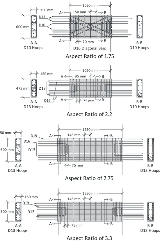
In this paper, the testing of four specimens with span-to-overall height ratios of 1.75, 2.2, 2.75 and 3.3 will be discussed. The reinforcement design for each specimen is shown in Fig. 2. Two designs were investigated depending on the span-to-height ratio. For beams with aspect ratios greater than or equal to approximately 2.2, a design that consists of longitudinal and transverse reinforcement only (i.e., no diagonal bars) was evaluated. For beams with lower aspect ratios, diagonal reinforcement designed to resist approximately 1/3 of the expected shear demand was used, as results from previous tests [4] had shown that some amount of diagonal reinforcement is needed in short coupling beams to achieve adequate drift capacity.
Load Cell Coupling Beam Actuator
Figure 2. Reinforcement details of test specimens.
As opposed to diagonally reinforced concrete beams for which confinement similar to that required for columns in special moment frames is required, HPFRC coupling beams have been found [9] to require this type of confinement only over half the beam depth from each beam end.
1050 mm 150 mm 600 mm D10 D13 A A D16 Diagonal Bars
Aspect Ratio of 1.75
70 mm 150 mm B B A‐A D10 Hoops 1050 mm B‐B D10 Hoops A A B B 95 mm 75 mm A‐A D13 Hoops D16 A 150 mm 475 mm B‐B D10 Hoops D13Aspect Ratio of 2.2
600 mm B A 1650 mm B 150 mm B‐B D13 Hoops 75 mmAspect Ratio of 2.75
A‐A D13 Hoops 145 mm D19 D13 D16 150 mm 500 mm A‐A D13 Hoops A A B B 1650 mm 75 mm 145 mm D19 D13Aspect Ratio of 3.3
B‐B D13 HoopsOver the remaining beam length, fiber reinforcement provides adequate confinement.
Design for shear in the HPFRC coupling beams was performed assuming that three mechanisms contribute to shear resistance: fiber reinforced concrete, transverse steel, and diagonal bars (if any). The amount of transverse reinforcement was selected such that the required contribution from fiber reinforced concrete would not exceed 0.42 ′, MPa (5 ′, psi).
Another aspect that was investigated was the use of precast HPFRC coupling beams in order to further facilitate construction. To prevent interference with the wall boundary reinforcement, the precast portion of the HPFRC coupling beams extended only to the wall cover (see shaded grey area in Fig. 2). Longitudinal bars (and diagonal bars, if any) were extended beyond the precast portion of the beam a full development length for anchorage. When diagonal bars were used, these bars were bent inside the precast portion such as to exit the beam horizontally. In order to prevent damage localization at the precast beam-wall interface, and thus a premature sliding shear failure, U-shaped or straight dowel bar reinforcement crossing the cold joint was used to force most of the beam inelastic deformations to occur away from the cold joint. The ease with which these precast HPFRC coupling beams can be placed on the jobsite is a major improvement over the construction methods currently used for diagonally reinforced concrete and steel coupling beams.
Experimental Results
The shear stress versus drift response for the four test specimens described above is shown in Fig. 3. The specimens were shown to develop a stable flexural response with energy dissipation and stiffness retention capacities comparable to those of well detailed diagonally-reinforced concrete coupling beams. Although diagonal cracking was observed throughout the span of the coupling beams, diagonal crack growth was shown to be well controlled by the combination of fiber reinforcement and transverse reinforcement. The result was that a majority of deformations came from plastic flexural hinges that developed near the ends of the beams.
As shown in Table 1, the specimens exhibited drift capacities between 4.9% and 6.8% (drift capacity is defined as the largest drift reached in both loading directions with a strength retention of at least 80%), with the larger drift capacities being associated with increased coupling beam aspect ratio. These large drift capacities are comparable to those observed for well detailed diagonally reinforced coupling beams with similar aspect ratios. Furthermore, these large drift capacities were observed despite the fact that these HPFRC coupling beam specimens were subjected to shear stresses approximately equal to 0.83 ′, MPa (10 ′, psi), the maximum nominal shear stress permitted by the ACI Building Code [1] for design.
It was observed that plastic deformations concentrated within the beam span away from the cold-joint between the precast HPFRC beam and the cast-in-place wall concrete. The reinforcement detailing provided across this joint, in the form of either U-shaped or straight dowel-bar reinforcement, effectively protected the joint and forced deformations into the more damage tolerant HPFRC section.
a) Aspect ratio of 1.75 b) Aspect ratio of 2.2
c) Aspect ratio of 2.75 d) Aspect ratio of 3.3
Figure 3. Shear stress versus drift response for test coupling beams. Table 1. Summary of test results.
ln/h b, mm (in.) h, mm (in.) Test Day fc’, MPa (psi) Measured Vmax, kN (kips) Vmax / (bh√fc’), MPa (psi) Drift Capacity* 1.75 150 (6) 600 (24) 52 (7550) 650 (146) 0.97 (11.6) 4.9 % 2.2 150 (6) 475 (18.75) 63 (9140) 570 (128) 1.00 (12.0) 5.8 % 2.75 150 (6) 600 (24) 68 (9870) 540 (121) 0.73 (8.76) 5.8 % 3.3 150 (6) 500 (20) 68 (9870) 500 (112) 0.81 (9.72) 6.8 % * Largest drift achieved in both directions with less than 20% strength loss
b: thickness; h: overall depth; Vmax: maximum shear
‐10 ‐5 0 5 10 ‐8 ‐4 0 4 8 Drift (%) Sh ear St re ss (M P a ) ‐10 ‐5 0 5 10 ‐8 ‐4 0 4 8 Drift (%) Sh ear St re ss (MP a ) ‐10 ‐5 0 5 10 ‐8 ‐4 0 4 8 Drift (%) Sh e a r St re ss (MP a ) ‐10 ‐5 0 5 10 ‐8 ‐4 0 4 8 Drift (%) Sh e a r St re ss (MP a )
The desig building story cor the use o basis for building was impl Figure 4. Each floo x 18 in.) Only lon in the sp facilitate to 0.71 was desi 0.29 ′ reinforce reinforce with low bottom. S gn develope in the city o re-wall struc of HPFRC c analysis an officials wa lemented fro . The Martin or level had cross sectio ngitudinal an pecimens wi d constructi ′ , MPa (4 igned such ′, MPa (3.5 ement was p ement ranged wer shear str Specified co ed for slende of Seattle, W cture designe coupling bea d design the as obtained a om the 12th fl n building, Se five couplin on, with a sp nd transverse ith aspect ra ion. Design 4 ′ to 8.5
that the she 5 ′, psi). provided ov d from 5-No ress demand ncrete streng Field Im er coupling b WA. The buil
ed by Cary K ams was ach e results from after constru floor up. eattle, WA ng beams an pan length o e reinforceme atios of 2.2, shear stres ′, psi) an ear stress d As in the ver half the
o. 22M (5-N ds to 3-No. gth ranged b mplementat beams using lding, The M Kopczynski hieved throu m the tests d uction had be Figure d each HPFR of 1.3 m (50
ent was used 2.75 and 3 sses in the nd transverse demand in t test specim e beam dep No. 7) bars 35M + 3-N between 41 a tion HPFRC wa Martin (Fig. 4 & Co from ugh a peer-r described ab egun, the H 5. Casting o RC coupling 0.5 in.) for a d in the beam 3.3 described coupling be e steel in the the HPFRC mens, specia pth from ea top and bot No. 32M (3-N and 69 MPa as implemen 4), is a 73 m m Bellevue, W review proc bove. Becau PFRC coupl of HPFRC in g beam had a span-to-he ms (i.e., no d d above, wh eams ranged e middle por material w al column-ty ach beam en ttom for the No. 11 + 3-(6,000 and 1
nted in a high m (240 ft) tal
WA. Approv cess and usin se approval ling beam d n coupling b a 76 x 46 cm eight ratio o diagonal bar hich substan d from 0.33 rtion of the b would not ex ype confine nd. Longitu e coupling b -No. 10) top 10,000 psi). h-rise l, 24-val of ng as from design beams m (30 f 2.8. rs), as ntially 3 ′ beam xceed ement udinal beams p and
Ready mix fiber reinforced concrete was used, with the fibers added at the concrete plant. The fibers were of the same type (high-strength hooked steel fibers) and used in the same dosage (1.5% volume fraction) as in the test specimens. Prior to addition of fibers, the mixture used exhibited self-consolidating properties. To verify that adequate fiber distribution could be achieved, small samples were cast and cut after hardening of concrete for visual inspection. Rather than using a precast operation as in the experimental program, the coupling beams were cast-in-place, using a crane and bucket operation (Fig. 5). Given the fact that the HPFRC material did not penetrate into the core of the wall boundary region, intermediate reinforcement was used as in the precast coupling beams to force most of the inelastic deformations to occur away from the cold joint and thus prevent a premature sliding shear failure. Overall, the construction of cast-in-place HPFRC coupling beams proved to be a very practical and successful operation.
Conclusions
Experimental evidence indicates that the use of a high-performance fiber reinforced concrete containing a 1.5% volume fraction of high-strength hooked steel fibers allows a substantial simplification of reinforcement detailing in coupling beams. In coupling beams with span-to-overall height ratios greater than or equal to approximately 2.2, a complete elimination of diagonal reinforcement is possible. In coupling beams with lower aspect ratios, an approximately 2/3 reduction in diagonal reinforcement was found to be possible. In all cases, special column-type confinement reinforcement is only needed at the beam ends due to the confinement provided by the fiber reinforcement. For further construction simplification, the proposed HPFRC coupling beams can be precast, eliminating the need for cast-in-place HPFRC. Drift capacities of the HPFRC coupling beam specimens with the proposed reinforcement detailing, when subjected to shear reversals with amplitudes comparable to the upper shear limit allowed in the ACI Building Code, ranged between approximately 5% and 7% for span-to-height ratios of 1.75 and 3.3, respectively.
The HPFRC coupling beam design was implemented into a high-rise building in the city of Seattle, WA. Construction of the HPFRC coupling beams, without diagonal bars and using a crane and bucket operation, proved very practical.
Acknowledgments
This research was funded by the US National Science Foundation through grant CMMI 0530383 and Bekaert Corporation. The opinions expressed are those of the writers and do not necessarily represent the views of the sponsors.
References
1. ACI Committee 318. Building Code Requirements for Structural Concrete (ACI 318-11). American Concrete Institute: Farmington Hills, MI, 2011.
Concrete, Special Publication-42, American Concrete Institute: Detroit, MI, 1974: 579-598.
3. Naish, D, Fry, JA, Klemencic, R, and Wallace, J. Reinforced concrete link beams: Alternative details for improved constructability. Report to Charles Pankow Foundation, UCLA-SGEL, University of California at Los Angeles, 2009.
4. Canbolat, BA, Parra-Montesinos, GJ, and Wight, JK. Experimental study on seismic behavior of high-performance fiber-reinforced cement composite coupling beams. ACI Structural Journal 2005; 102 (1): 159-166.
5. Parra-Montesinos, GJ, Wight, JK, and Setkit, M. Earthquake-resistant coupling beams without diagonal reinforcement. Concrete International 2010, American Concrete institute; 32 (12): 36-40.
6. Lequesne, RD, Parra-Montesinos, GJ, and Wight, JK. Seismic behavior and detailing of high-performance fiber reinforced concrete coupling beams and coupled wall systems. ASCE Journal of Structural Engineering 2013; 139(8): 1362-1370.
7. Setkit, M. Seismic Behavior of slender coupling beams constructed with high-performance fiber-reinforced concrete, PhD. Dissertation, University of Michigan, Ann Arbor, MI, 2012.
8. Liao, W-C, Chao, S-H, Park, S-Y, and Naaman, AE. Self-consolidating high-performance fiber-reinforced concrete (SCHPFRC)–Preliminary investigation. Report No. UMCEE 06-02, University of Michigan: Ann Arbor, MI, 2006.
9. Lequesne, RD. Behavior and design of high-performance fiber-reinforced concrete coupling beams and coupled-wall systems, PhD. Dissertation, University of Michigan, Ann Arbor, MI, 2011.