Year 2020
Ph.D. Thesis
Nonlinear interactions between US waves and contact
interface
Jointly awarded at the University of Rome ‘La Sapienza’
Dottorato di ricerca in Meccanica Teorica ed Applicata XIX ciclo
and at the
‘University of Bordeaux’
Ecole doctorale: Sciences pour l’ingénieur (SPI) Spécialité: Mécanique
By
Dorra NOUIRA
PhD Committee :President Odile ABRAHAM Research director (GeoEND, Nantes)
Co-director Anissa MEZIANE Professor (University of Bordeaux)
Co-director Francesco MASSI Associate Professor (University of Rome ‘La Sapienza’)
Reviewer Ilker Murat KOC Professor (ITU Turkey)
Reviewer Bruno LOMBARD Research director (LMA, Marseille)
Examiner Laurent BAILLET Professor (Université Grenoble)
Examiner Adnan AKAY Professor (Bilkent university, Ankara)
Research laboratories:
Dipartimento di Meccanica ed Aeronautica (DIMA) Institut de mécanique (I2M)
Acknowledgements
This thesis arises in the framework of a ‘cotutelle’ thesis between La Sapienza of Rome and l’Institut de Mécanique et d’Ingénierie de Bordeaux (I2M). Firstly, I would like to thank both institutions for supporting this research and making it possible. Then, I am grateful to my French and Italian supervisors: the Professors Anissa Meziane and Francesco Massi for their professional guidance during the development of this research work. It has been a great pleasure working with you. Thank you for your support both scientifically and morally. I would like to also express my gratitude to the Professor Laurent Baillet for his valuable collaboration and contribution to the research work. Sincere thanks goes to professors Bruno Lombard and Murat Ilker Koc for accepting the responsibility of reviewing the thesis. I would like to finish by extending my greeting to all friends, colleagues, professors, people that I have had the opportunity and the pleasure to meet during the thesis. Among them, Marie-Marthe, Fiona, Amir, Federica, Manuel, Mailcol and Ilaria.
Concluding, a last but certainly not least thanks to my family Jalel, Lilila and Amine to whom this thesis is dedicated.
Table of contents
ACKNOWLEDGEMENTS ... 2
GENERAL INTRODUCTION ... 5
CHAPTER 1: OVERVIEW OF MECHANICAL MODELS OF ROUGH CONTACT ... 8
1.1 INTRODUCTION ... 8
1.2 MODELING OF CONTACT INTERFACES ... 12
1.2.1.BILINEAR MODELS ... 12
1.2.2.CONTACT LAWS... 14
1.2.2.1. Contact unilateral ... 14
1.2.2.2. Rough interface models in compression... 15
1.2.2.3. Rough interface modelling with a traction-free condition ... 16
1.2.2.4. Models involving adhesion ... 17
1.3 NDT METHODS FOR INTERFACE CHARACTERIZATION ... 20
1.3.1. NL RESONANCE SPECTROSCOPY ... 20
1.3.2. GENERATION OF HIGHER HARMONICS ... 21
1.3.3. NL SPECTROSCOPY BY WAVE MODULATION ... 24
1.3.4. SUB-HARMONICS ... 27
1.4 POSITIONING OF THE THESIS WORK ... 28
CHAPTER 2: MATERIALS AND METHODS ... 32
2.1 DESCRIPTION OF THE METHODOLOGY ... 32
2.2 EXPERIMENTAL TOOLS ... 33
2.2.1 EXPERIMENTAL SET-UP ... 33
2.2.2 INTERFACE STIFFNESS PRELIMINARY CHARACTERIZATION... 35
2.3 NUMERICAL IMPLEMENTATION TOOLS ... 37
2.3.1 1D MODELLING OF THE EXPERIMENTAL SYSTEM ... 37
2.3.2 SIMPLIFIED MODEL ... 38
2.3.3 EQUATIONS ... 39
2.3.4 NUMERICAL IMPLEMENTATION ... 44
2.3.5 ALGORITHM ... 49
2.4 CONCLUDING REMARKS ... 52
CHAPTER 3: NONLINEAR ANALYSIS OF THE RCCM CONTACT LAW WITH ADHESION ... 54
3.1 VALIDATION OF THE NUMERICAL MODEL ... 55
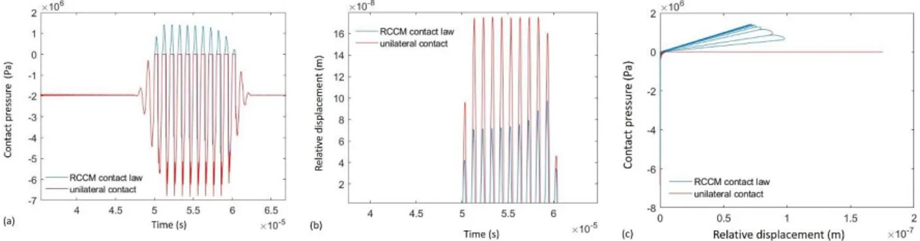
3.2 INTERFACE DYNAMIC BEHAVIOUR: COMPARISON BETWEEN RCCM CONTACT LAW AND UNILATERAL LAW ... 60
3.3 PARAMETRIC ANALYSIS ... 66
3.3.2 INFLUENCE OF THE FREQUENCY ON THE NONLINEAR SIGNATURE OF THE RCCM CONTACT LAW ... 71
3.3.3 INFLUENCE OF THE DECOHESION ENERGY ON THE NONLINEAR SIGNATURE OF THE RCCM CONTACT LAW 80 3.3.4 INFLUENCE OF THE VISCOSITY ON THE NONLINEAR SIGNATURE OF THE RCCM CONTACT LAW ... 87
3.1. IDENTIFICATION OF CONTACT LAW PARAMETERS ... 93
3.4 CONCLUDING REMARKS ... 96
CHAPTER 4: NORMAL CONTACT STIFFNESS IN COMPRESSION ... 97
4.1 APPROACH FOR THE NONLINEAR STIFFNESS ANALYSIS ... 97
4.2 NEW CONTACT LAW: MODIFIED POWER-LAW ... 98
4.3 EXPERIMENTAL AND NUMERICAL COMPARISON ... 100
4.3.1 DYNAMIC RESPONSE OF THE CONTACT SYSTEM ... 100
4.3.2 NONLINEAR RESPONSE OF THE INTERFACE ... 104
4.4 CONCLUDING REMARKS ... 111
CHAPTER 5: CONTACT LAW IN COMPRESSION AND TRACTION ... 113
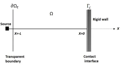
5.1 WAVE SCATTERING CONFIGURATION ... 114
5.2 VALIDATION OF THE NUMERICAL MODEL ... 116
5.2.1 ANALYTICAL SOLUTION FOR LINEAR SPRING WITH AND WITHOUT CONTACT LOSS ... 116
5.2.1.1 Without contact loss ... 117
5.2.1.2 With contact loss ... 119
5.2.2 NUMERICAL AND ANALYTICAL COMPARISON ... 121
5.3 RESULTS AND DISCUSSION ... 123
5.3.1 LINEAR SPRING IN COMPRESSION ... 124
5.3.2 NONLINEAR STIFFNESS IN COMPRESSION ... 129
5.3.2.1 Undamaged interface ... 130
5.3.2.2 Damaged interface ... 137
5.4 CONCLUDING REMARKS ... 142
GENERAL CONCLUSION ... 144
6.1 ORIGINAL MAIN CONTRIBUTIONS ... 144
6.2 OUTLINES AND FUTURE STEPS ... 145
General introduction
The identification of interface features is one major topic in different research domains and with several industrial applications. As an example, tribology and structural health monitoring are often confronted to the identification of interface parameters for the analysis of either the contact or structural response.
More specifically, the early characterisation of material damage is a key element in controlling the durability and reliability of in-service components and materials. Conventional non-destructive testing (NDT) methods often offer interesting solutions in terms of damage characterisation. However, these methods fail to detect localised damage such as closed cracks or micro-cracks. The latter phenomenon occurs frequently in the industrial field by fatigue or corrosion, for example, and represent the precursor of the final failure. It is, therefore, very important to identify.
Damage is often preceded by local changes in the mechanical characteristics of the material, which increase its nonlinear properties. A closed crack could be seen as a zero-volume heterogeneity. In the following, the term ‘contact interface’ will be then used to refer to both interfaces between solids in contact and localized defects inside the bulk of the solids.
In the recent decades, wave propagation has been proposed as a powerful tool for investigating the nonlinearities introduced into a system by material damaging or contact interfaces. In fact, during the propagation of acoustic waves, their spectrum is enriched with new frequencies. This is due to the nonlinear wave-crack interaction, which is commonly manifested by the generation of harmonics, i.e. multiple frequency components of the incident frequency. In order to detect and characterize defects (contact interfaces), it is therefore opportune to develop methods that exploit these particular wave-interface interactions. From recent works, nonlinear methods seem to have the potential to detect and characterize localized defects. The challenge is to set up a method sensitive to this type of interactions (detecting and characterizing them) while being independent on other nonlinearities of the system (material, electronic amplification etc.). For this purpose, a detailed understanding and modelling of the physical mechanisms, involved in the wave-interface interaction, is required to analyse the nonlinear signature and identify the governing contact parameters. The determination of these parameters could be then be used in non-destructive methods for the interface characterization.
In this context, this PhD work focuses on the analysis of the wave-interface interaction, while accounting for different phenomena, both in compression and in traction. The main objective is to understand the mechanisms responsible for the nonlinearity generated by the interface-wave interaction for characterization purposes. The proposed approach is based on a combination of numerical and experimental analyses. Indeed, given that the interface phenomena involved in the nonlinear contact response are extremely complex, the numerical analysis allows a better understanding of these types of interactions as a function of the involved physical parameters. This is achieved by using adapted numerical models to investigate the effect of each parameter at once. On the other hand, the experimental analysis allows retrieving specific information for the model and validating the numerical results on a real case. The practical objective of the thesis is to develop the tools and propose the outlines of a methodology allowing the identification of the parameters governing the interface-wave interaction, potentially useful for interface characterization.
The first Chapter opens with a brief presentation of the different types of nonlinearities encountered during wave propagation with a particular interest to contact nonlinearity, which is a general term used to describe the contact phenomena occurring at the interface during dynamic or acoustic excitation. In order to analyse the mechanisms involved in the contact nonlinearity, numerical modelling is required. The first section presents then the recent literature on the different modelling approaches of the interface-wave interaction. The analysis of existing methods enables to identify the requirements for the characteristics of a suitable numerical tool. In the second section of the chapter, the nonlinear NDT methods applied to the interface characterization are presented. The study will help to decide on the methods to be used in the following.
The second Chapter presents the overall approach and the tools used to carry out the analyses developed in this PhD work, concerning the characterization of contact interfaces in mechanical systems. First, the methodological approach of the research work, done during the thesis, is presented. Then, the numerical tools developed and used to carry out the numerical nonlinear contact analyses are described. Finally, the experimental tools, used to retrieve interface parameters and validate the numerical model are presented. All the different tools have been assembled in this work for investigating the main features of a contact interface, both in traction and compression.
Once the numerical models have been set up and numerically validated, they allow obtaining the acoustic response due to the interaction of acoustic waves with an interface, and thus allow investigating the influence of the various parameters on the generated nonlinearity. A contact
law describing adhesion in traction (elasticity coupled with damage) and non-penetration conditions in compression has been, first, introduced. The objective of the third Chapter is then the investigation of the interaction between longitudinal waves and a contact interface that follows this contact law, through the evolution of fundamental and second harmonics. A parametric analysis has been carried out and resulted in a promising approach for characterization.
However, because real surfaces are rough and not perfectly flat, this approach is not suitable for modelling the weak nonlinear response of tightly closed interfaces. In this context, the aim of the fourth Chapter is to present a numerical and experimental analysis to provide a basic insight into the nonlinear vibrational response of a contact interface, as a basis for evaluating and modelling the nonlinear contact through stress-dependent stiffness in compression. So far, the effects of introducing contact stiffness in compression or traction have been studied separately in different contexts. The fifth Chapter presents an overall approach for modelling the nonlinear scattering induced by a contact interface by combining the two latter laws, with the aim of capturing both the weak nonlinear response of a rough interface and the strong nonlinear response of a “clapping” interface. This association of nonlinear behaviours is missing from the literature and the study of its effects on the wave-interface interaction would make it possible to complete the previous studies in the nonlinear contact framework.
Chapter 1: Overview of mechanical models of rough
contact
1.1 Introduction
It is inevitable that all components and structures demonstrate a process of deteriorating of their properties and performances with time. Apart from ageing, the main reason for this is initiation and evolution of damage, under in-service loading and/or environmental conditions. Although in practice it is possible to foresee ageing or continuous deterioration, severe and/or unexpected structural damage could have fatal consequences. Thus, early damage detection and characterization is of a prime importance for safety management of structural assets. An objective of non-destructive testing (NDT) is to detect these defects and characterize them in order to decide on their degree of risk to the structure. This process of characterizing and understanding the contribution of the defect to the dynamic response of the system is crucial for many applications. These include robotic applications [1], grippers [2], micro-bearings [3], adhesive surfaces [4] and wherever dry contact occurs between solids [5]. In the case of structural diagnostic, health monitoring and quality control of components and joints, these are based on the measurement and interpretation of wave interaction with joint interfaces or component defects [6].
Among the various NDT methods, ultrasound allow an inspection of the whole volume of the structure, with relatively easy and non-restrictive processing in terms of safety and regulations. During their propagation in nonlinear media, the behavior of us or vibration waves can be altered. In fact, this propagation can lead to potential distortions in the signal, pseudo periodic or even chaotic behaviour. These nonlinear behaviours observed in different solids may be the result of a variety of mechanisms occurring at different scales. These mechanisms can be classified into three categories: geometric nonlinearities, material nonlinearities and contact nonlinearities.
Geometric nonlinearities are often associated with large deformations. Therefore, they are not considered in the context of linear vibro-acoustic, which is based on the assumption of small deformations.
The nonlinearities within the material correspond to a nonlinear stress-strain relationship. There are two main categories of material nonlinearities: classical and non-classical
nonlinearities. The classic volume nonlinearity is related to the microscopic effects distributed in the volume of the material. This type of nonlinearity can be considered in the mechanics equations by introducing the elastic constants of higher orders. The non-classical volume nonlinearities can be related for example to the hysteretic behaviour of the material or slow dynamics [7]. The effects induced by these nonlinearities depend on the propagation distance (nonlinearities within the volume).
Contact nonlinearities are considered non-classical, but they are localised. One example is intermittent ‘clapping’, which is similar to a shock between two constituents of a system.
Herein, localised nonlinear contact problems are the focus of this work, in the context of vibro-acoustics. This problem is related to the nonlinear interaction between one (or more) acoustic waves(s) and an interface (e.g. closed cracks). The nonlinearities generated by the wave-interface interaction are related to contact dynamics between the opposite faces of the wave-interface, when excited with a sufficiently large vibro-acoustic excitation. For a normal incidence, the dynamic of contact is mainly translated by the ‘clapping’ mechanism, caused by alternating opening and closing of the interface. Indeed, when a sufficiently large incident wave reaches an imperfect contact interface at normal incidence, the compression part is transmitted while the part in traction opens the interface and is reflected. The transmitted signal loses symmetry with respect to its mean value. This form of distortion gives rise to generation of even and odd harmonics. The principle of this mechanism is given in Figure 1.
Figure 1 Nonlinear contact for an interface and a longitudinal wave under normal incidence: only compression waves are transmitted through the interface
However, in case of more realistic interface (e.g. crack) the surfaces in contact are not generally flat due to roughness and other factors. In addition, loss of contact does not occur instantly; the interface is damaged before being completely peeled off. This phenomena is described by the adhesion mechanism. Several different theoretical approaches have been proposed in the literature; however none of them have gained wide acceptance mainly because they separate these different nonlinear mechanisms. In this work, different nonlinear effects will be combined (roughness, clapping and adhesion) in order to enrich the physical understanding of nonlinear phenomena associated with interface-wave interactions.
Experimentally, several US dynamic and vibration methods have been developed for interface characterization. Conventional NDT methods consist of measuring the evolution of a parameter such as propagation velocity, attenuation or the transmission and reflection coefficients of the waves reflected by the interface, in order to determine the mechanical properties of the material, an interface or to detect the presence of a defect.
A defect will change the phase or amplitude of the measured signal and thus be detected. However, if the damaged area does not sufficiently interfere with sound propagation, as may be the case for a micro-crack distribution or closed crack, the linear NDT methods are no longer effective. However, a closed crack is as damaging as an open one to the structure. To overcome this limit, nonlinear acoustic methods can be used. In contrast to linear methods, which rely on amplitudes or phase effects, the nonlinear methods are based on changes in the frequency content of the vibro-acoustic wave during its propagation (see Figure 2). Changing the frequency of the signal, or even appearance of new frequencies in the spectrum, are the result of the interaction between a high amplitude wave and heterogeneities, such as plastic deformation zone, a crack or a contact interface with a nonlinear mechanical behaviour.
Figure 2 Illustration of the fundamental approach for nonlinear NDT methods. The focus here is on generation of higher harmonics.
Despite the different nonlinear mechanisms, whether in volume or contact, generate similar nonlinear effects; there is a general agreement that these nonlinear effects are relatively small in an undamaged material and remarkably strong in the presence of defect. This is the main attraction of NDT methods using nonlinear acoustics for defect detection. The main condition for collecting a nonlinear response is to generate significant excitations. Various methods can be used to do so: hammer impact, ultrasonic transducers, lasers, etc. Depending on the type of excitation used, most of these methods can be classified into three main categories:
- Excitation with a single acoustic wave: method of generating higher harmonics, sub-harmonics, nonlinear resonance.
- Vibro-acoustic excitation: method based on modal excitation combined with ultrasonic excitation leading to nonlinear modulations.
- Excitation with two acoustic waves. In the presence of a defect, a variant consists of modulating high-frequency and low-frequency waves.
The efficiency of these nonlinear methods has been demonstrated in numerous experiments. However, nonlinear phenomena associated with the interaction of damage with an us wave is not fully understood. This relates particularly to wave-interface interactions. A major problem is the variety of physical phenomena that can influence an interface behaviour. In fact, it is sometimes very difficult to separate the mechanisms involved in the generation of nonlinear
effects. It is clear then that modelling and numerical simulations, where various mechanisms can be easily switched on and off, are required for an in-depth analysis of these interactions. Therefore, the first part of this chapter covers various modelling aspects related to nonlinear wave-interface interactions. It is important to note that this section does not intend to review all the models that have been proposed. Only models used or related to our study will be included in the review.
The nonlinear interaction between a wave and interface generates several nonlinear effects. Hence, several NDT methods have been developed based on these effects in order to monitor damage in solids. The second part of the chapter reviews existing nonlinear methods for interface characterization.
1.2 Modeling of contact interfaces
One of the objectives of the NDT is to detect and characterise cracks as early as possible. A crack can be viewed as a finite size contact interface whose mechanical behaviour is nonlinear and complex. In this regard, nonlinear contact is responsible for several acoustic phenomena, such as the generation of higher and lower harmonics, hysteresis effects and amplitude modulation if two waves meet at the interface. Contact phenomena are complex, and interface behaviour is, in general, nonlinear.
In this section, different approaches to modelling the nonlinear interaction between a propagating wave and contact interface are presented. These approaches can be classified in two categories: the first one models the interface as a volume with nonlinear properties. Subsequently, it allows defining the relationship between the contact pressure and strain. The second one is based on the modelling of the interface by a contact law. Thus, it provides a relation between the contact pressure and the relative displacement at the interface.
1.2.1. Bilinear models
The bi-linear model is one of the best-known nonlinear interface models. It is based on bi-linear stiffness [8] (see Figure 3), also known as stiffness asymmetry, which consists in modelling the interface as a zone where the stress-strain relationship is asymmetrical. The relative behavioural law is a piecewise continuous function as follows
𝜎 = 𝐸ɛ (1 − 𝐻(ɛ − ɛ0)∆𝐸 𝐸 )
1.1
where 𝐻 is the Heaviside function, ɛ0 is the initial static strain and ∆𝐸 = (𝐸 − (𝑑𝜎
𝑑ɛ)ɛ>0) is the
loss of stiffness.
This model is constructed based on the lateral motion of the interface, in the presence of tension and compression, leading to an interface opening/closing. When the interface is open, the global stiffness is reduced; when the interface is closed, the stiffness is not affected [9] [10]. For one-dimensional case, this model treats the interface as a spring with a nonlinear stiffness coefficient consisting of two different stiffness values.
Figure 3 Evolution of the stress as a function of the strain according to the bi-modular model.
The bi-linear model is able to reproduce higher harmonics, but it still has several limitations. The first one concerns the absence of odd harmonics, as opposed to experimental observations [11] [12]. The second is the abrupt change in rigidity during the transition between the open and closed configurations of the interface. The homogeneity of the model is another important constraint [8].
According to other authors, due to the presence of roughness, the interface behaviour becomes more complex; hence, the shift from one stiffness value to another is not enough to represent it properly. Indeed, the actual contact area of an interface depends on the progressive deformation of the asperities under the applied load. Consequently, different models based on
contact laws, have been developed in order to account for the latter phenomena and will be presented in the next paragraph.
1.2.2. Contact laws
An alternative approach to model the nonlinear interaction between a propagating wave and a contact interface is to use contact laws. The dynamic behaviour of the interface during acoustic or vibration excitation may result in alternation of opening and closing of both sides of the interface.
1.2.2.1. Contact unilateral
An incident wave generates a compressive stress 𝜎𝑖, which in turn creates a normal stress 𝜎 at
the interface. To simplify, it is assumed that no load is applied to the solid. The unilateral contact (or Signorini’s law) is the written:
{
[𝑢] ≥ 0 𝜎(𝑡) ≤ 0 [𝑢]𝜎(𝑡) = 0
1.2
where [u] is the relative displacement at the interface.
The first line of this system ensures the non-penetration of the solid through the rigid interface. When [𝑢] > 0, the interface is open. The second equation indicates that only compressive stress can exist at the interface. When opening occurs, the contact pressure σ is null. Finally, the third line is called the complementarity equation. It ensures that the interface is either open or closed.
The first analytical model explaining the generation of higher harmonics in the case of a closed crack using a unilateral contact law was reported by Richardson in 1979 [13]. The model studies the nonlinear interaction between a plane longitudinal wave in normal incidence and a flat contact interface separating two semi-infinite elastic media. The two sides of the interface are held in contact by an applied pre-stress. The unilateral contact law describes the alternation of opening and closing of the interface during acoustic excitation while ensuring the non-interpenetration during contact phases. The evolution of the second harmonic amplitude was studied as a function of a non-dimensional load factor and showed a passage through an optimal
value. These results were experimentally validated in the case of a contact interface between two blocks of aluminium [14].
1.2.2.2. Rough interface models in compression
One of the main methods used to model a contact interface is to use a spring and a viscous damper in parallel. Contact stiffness can be obtained from analytical contact models, for instance, the Herzian contact model for spherical contacts [15]. In the case of rough surfaces in contact, the Greenwood and Williamson [16] statistical model and its successive reformulations [6] [17] [18] [19] have been used to obtain overall mean stiffness. Experimental values have been extracted using indirect methods [20] or system identification methods [21]. Recently, Jin et. al. [22] used a quasi-static model developed within the GW framework, in which all the microscopic geometric features of contact interfaces are extracted directly from high-resolution scanning electron microscopy (SEM) images of real fatigue cracks.
However, the development of increasingly sophisticated numerical models with contact interfaces means that more reliable and fine contact parameters need to be defined. Contact stiffness has been proved to be sensitive to contact conditions such as contact pressure [23] [24] [25], third body rheology [26] and the true area of contact [27].
In more detail, the force is supported by surface asperities. As the force increases, more asperities come into contact, while each asperity undergoes flattening deformation. In [28], three contact states can be identified: total sliding, partial slip and contact loss. In the case of partial slip, roughness has been described by Aleshin [28] using the Method of Memory Diagrams (MMD), a model developed to describe partial slip for rough surfaces in contact. The MMD model was then extended to take into account the other two regimes of total sliding and contact loss [29] [30]. The contact interface has a further nonlinear behaviour due to asymmetry between traction [31] [32] and compression configurations. During compression, the change in the contact interface configuration, as a function of contact pressure, also results in nonlinearity in the interface response.
When these nonlinearities are activated by the interaction between propagating waves and the contact interface, higher-order harmonics are then generated [33]. While these effects have been well studied in the ultrasonic field [34], they also represent a new area of investigation from a vibrational point of view [17]. In particular, the generation and features of second harmonics [35] deserve to be further analysed and exploited.
1.2.2.3. Rough interface modelling with a traction-free condition
The nonlinear stiffness laws presented in section 1.2.2.2, aim to represent the nonlinear compliance introduced by rough surfaces asperities during compression, which has been experimentally observed and reported in literature [36]. However, these laws do not describe the zero-stress condition corresponding to a loss of contact and is, thus, limited to cases where the interface remains in contact during wave propagation. By contrast, the unilateral contact, introduced in section 1.2.2.1, describes a traction-free condition during contact loss. However, it considers an infinitely rigid contact in compression, limiting the validity to perfectly smooth interfaces. These two laws are complementary and have been combined in [37] where the nonlinear stiffness has been described by quadratic springs:
{𝜎(𝑡) = −𝜎0+ 𝐾0[𝑢] − 𝐾1[𝑢]
2 ≤ 0, [𝑢] ≤ [𝑢]
𝑐 during contact
𝜎(𝑡) = 0, [𝑢] ≥ [𝑢]𝑐 during loss of contact
1.3
where the contact pressure σ is characterized by a spring law as long as it remains negative. When the contact pressure reaches zero, which is attained for a critical interface gap opening [𝑢]𝑐, the contact is lost and the stress subsequently remains equal to zero while the relative
displacement [𝑢] increases. This contact law ensures that both strong nonlinear response induced by clapping and the nonlinear response due to rough surface contact are considered. The results show that the linear response is hardly modified by the presence of nonlinear springs, contrary to the second harmonic, whose amplitude is increasing with the nonlinear spring constant and decreasing with the frequency. The second harmonic response shows a peak of amplitude for low compression stress (see Figure 4).
Figure 4 Evolution of (a) the second harmonic as a function of the non-dimensional load ξ, through a variation of the pre-stress 𝝈𝟎 for a nonlinear spring model with loss of contact. The nonlinear stiffness 𝑲𝟏 is varied from 0 to 900
MPa/μ𝒎𝟐. The loss of contact is marked by the red circles in (a). (b) Second harmonic as a function of the
non-dimensional load ξ, for different incident frequency and a fixed value of 𝑲𝟏= 𝟐𝟎𝟎 MPa/μ𝒎𝟐. The incident wave
amplitude is defined to generate a constant incident stress of 𝝈𝒊𝒎𝒂𝒙= 𝟏 𝑴𝑷𝒂. [37]
1.2.2.4. Models involving adhesion
In addition to interface roughness, the nonlinear contact between a wave and an interface concerns imperfect interfaces that allow de-cohesion. It is therefore the object of a growing interest with regard to the possibilities offered for the detection of closed cracks and adhesion imperfections during a structural bonding. Lemaitre [38] has given a formulation of interface damage based on a visco-plastic analysis restricted to a surface. Needleman [39] has proposed a de-cohesion model without friction, based on atomistic considerations. An exponential representation is used for the interface potential. A few years later, Tvergaard [40] introduced a non-dimensional damage parameter to include a non-reversible evolution of de-cohesion. The same author added the coupling with frictional behaviour, which is active only when adhesion is totally broken. This induces a non-smooth evolution of the contact forces, which turn back to zero before friction starts.
Some works have been done considering an interphase model with the presence of a third body [41]. Although a third body approach would be attractive for the sake of simplicity of the concept, numerical simulations are difficult for two reasons. The first one is that the parameters and the real geometry of the third body are very hard to determine. The second one is that the numerical treatment (mesh..) is difficult because the interphase domain is one hundred to one
thousand smaller than the other considered domains. On the contrary, asymptotic methods and theoretical studies on the equivalent behaviour of the third body when the thickness decreases to zero are very constructive. One of the widely used models is the RCCM (Raous, Cangémi, Cocu and Monerie) contact law [42]. It is based on a mathematical and thermodynamic formulation of an interface law including unilateral contact, friction and adhesion and derives from the principle of virtual powers and thermodynamic laws.
The constitutive parameters of the model are the following
𝐶𝑁 and 𝐶𝑇 (N/m) are the initial stiffnesses of the interface 𝑤 (J/m2) is the limit of decohesion energy
𝜇 is the friction coefficient
𝑏 (N.s/m) is the viscosity of the adhesion evolution
Adhesion is characterized, in this model, by the internal variable β, introduced first by Frémond [43] [44], which denotes the intensity of adhesion. It takes its values between 0 (no adhesion) and 1 (perfect adhesion). The use of a damageable stiffness of the interface, depending on β, ensures a good continuity between the two contact conditions (initial adhesion and final frictional sliding) during the competition between friction and adhesion.
Initially, when the adhesion is complete (β=1), the interface is elastic as long as the energy threshold 𝑤 is not reached. After that, damage of the interface occurs and consequently, on the one hand the adhesion intensity β and the apparent stiffness β2𝐶𝑁 and β2𝐶𝑇 decrease, and on the other hand, friction begins to develop. When the adhesion vanishes totally (β = 0), we get the classical Signorini problem with Coulomb friction.
Figure 5 gives the normal and tangential behaviours of the interface during loading and unloading [42]. It should be noted that the Signorini conditions are strictly imposed when compression occurs. Regularisations such as penalisation or compliance are not used.
Figure 5 RCCM contact law. (a) Normal behaviour (𝒖𝑻= 𝟎 ) [42]. (b) Tangential behaviour (𝑹𝑵 is constant) [42].
The initial conditions are supposed to be complete adhesion (𝛽 = 1) and zero displacement (𝑈𝑇 = 𝑈𝑁= 0). Considering first the normal behaviour in Figure 5 (a), under compressive action, the non-penetration condition is strictly verified (𝑈𝑁= 0).
Under traction (𝑈𝑁≥ 0), an adhesive resistance (𝑅𝑁 = 𝐶𝑁𝑈𝑁𝛽2) is active (elasticity with
damage). Three phases can be observed. During the first one, the adhesion intensity 𝛽 is equal to 1 and the interface behaves like a spring with stiffness 𝐶𝑁. The intensity of adhesion starts
to decrease when the displacement is sufficiently large such that the stress becomes larger than the elastic limit. The viscosity introduces, in addition to a dependence on strain velocity, a shift in the decay of the stress in relation to the damage and thus a normal maximum stress exceeding the elastic limit (see Figure 5 (a), ref [42]). When adhesion is totally broken, the classical Signorini problem is obtained.
Considering now the shear behaviour Figure 5 (b), note first that the friction acts only if a normal compression is applied; if a normal traction is applied (𝑈𝑁 > 0), the sliding limit
(𝜇|𝑅𝑁− β2𝐶𝑁𝑈𝑁|) is zero and the tangential behaviour is elastic with damage (𝑅𝑇 =
β2𝐶
𝑇𝑈𝑇). Under compression, the sliding limit is (𝜇|𝑅𝑁| because 𝑢𝑁 = 0 ). As long as the
norm of the tangential force ‖𝑅𝑇‖ is smaller than the sliding limit, sliding does not occur. When the sliding limit is reached, an elastic tangential displacement occurs. The adhesion begins to decrease when the adhesive limit is reached and evolution of β is decreased. When adhesion is lost (β goes to zero), the usual Coulomb friction conditions are obtained.
These different mechanisms, involved in the interface-wave interaction, are generally studied separately. There is little literature of models studying different nonlinear phenomena at the same time particularly roughness due to imperfect surfaces, clapping and adhesion. One of the
objectives of this thesis is to investigate these phenomena independently and then combine them for assessing their impact on the interface behaviour. The nonlinear interaction between wave(s) and contact interface is manifested by the enrichment of the spectrum with additional frequency components called harmonics, which is particularly interesting for interface characterization. In the next section, different nonlinear methods applied for interface characterization are reviewed.
1.3 NDT methods for interface characterization
Various nonlinear processes have been studied in the context of nonlinear characterization: nonlinear resonances, harmonic generation, non-linear wave-modulation spectroscopy, sub-harmonics… It is often observed that the measurements of nonlinear parameters from these nonlinear processes are more sensitive to the presence of an interface than linear elastic parameters (measured through linear vibro-acoustic methods), especially at early damage states [45]. Driven by industrial needs to improve the detectability of defects, nonlinear characterization methods have been the subject of a considerable number of research work. These methods can be grouped together under the abbreviation NEWS (Nonlinear Elastic Wave Spectroscopy) [46]. They differ by the nonlinear phenomenon exploited.
1.3.1.
NL resonance spectroscopy
One of the non-linear phenomena caused by the presence of microscopic heterogeneities and defects distributed in volume of the material is the variation of the resonant frequency when increasing the excitation amplitude [47]. This phenomenon is directly related to the presence of heterogeneities, thus it can be used to quantify the damage level. This method is referred to as nonlinear resonance ultrasound spectroscopy NRUS [46] [48].
The method consists of evaluating one or more frequency peak shifts while increasing the amplitude. In fact, a sample is subjected to progressive damage induced by excitation around its resonance frequencies. The amplitude is increased gradually and the new resonance frequency is evaluated at each iteration. The resonance frequency shift indicates the presence of damage. Van Den Abeele and al. applied this technique to artificial slate slabs [48], which were progressively damaged by successive impacts in the centre of the slab. The shift in
resonance frequency is obtained when the excitation increases and is higher in the case of damaged sample. Figure 6 gives an example of an experimental result.
Figure 6 Amplitude-dependant resonance curves for (a) an intact sample and (b) damaged sample [48]
The frequency shift is characterized by a slope that accounts for the nonlinear parameter in this method. In fact, the slope increases with the damage. Therefore, the method quantifies the overall damage of the material; and has been applied to concrete [49], bone [50] and composite materials [51]. However, this method requires numerous measurements.
1.3.2.
Generation of higher harmonics
The phenomenon of higher harmonic generation is one of the oldest phenomena in nonlinear acoustics. The first experimental demonstration of this phenomenon in solids was reported in 1963 by Breazeale and Thompson [52] and by Gedroits and Krasilnikov [53]. In these two studies, the generation of harmonics is the result of classical nonlinearity. In 1965, Hikata, Chick and Elbaum [54] showed that the phenomenon of higher harmonics generation increases considerably in the presence of defects. This work studies the detection of dislocation defects in metallic materials. Yermilin and al. [55] reported the first studies of harmonic generation in the case of fatigue cracks in 1973 and by Buck and al. [56] in 1976. These initially consider an artificial crack made by two aluminium blocks in contact. In a second step, the test was carried out on aluminium specimen AL2024 with a real fatigue crack. In both cases, the nonlinear interaction between a longitudinal wave at normal incidence and the pre-stressed contact interface was investigated. The results of this interaction show that the amplitude of the generated second harmonic presents a maximum as a function of the applied compression,
which was confirmed by Richardson’s analytical model [13] published in 1979. A similar result was obtained by Taehyung Nam and al [57] using a longitudinal wave with oblique incidence on an interface of contact between two aluminium blocks. The reflected wave is analysed according to the normal stress applied. For the two angles (22.5° and 45°), the amplitude of the second harmonic goes through a maximum but with different amplitudes. The optimal of second harmonic amplitude as a function of the applied compression is characteristic of the nonlinear contact. Further details will be discussed in the chapter 3.
Another possibility to detect the damage is to study the evolution of the nonlinear parameter 𝛽∗= 𝐴2
𝐴12
as a function of the applied load. Although this definition of the nonlinear parameter
comes from the classical nonlinear acoustics theory, it is also used to assess nonlinearity caused by an interface. Buck and al. [56] show that this parameter reaches a maximum value when the applied compression is zero, and decreases exponentially as the applied compression increases. Biwa and al. obtained similar results again on aluminium blocks [58]. However, the evolution of the second harmonic shows a slight hysteresis effect depending on the applied load [58]. Lee and Jhang studied the evolution of the nonlinear parameter along a fatigue crack in an aluminium specimen [59]. A constant pressure is maintained on the transducers by a pneumatically controlled system to ensure a stable and repeatable measurement. For constant compression applied to the specimen, the nonlinear parameter 𝛽∗decreases progressively as it approaches the crack tip, and becomes constant once the point of the crack has been surpassed. Due to the stress concentration at the end of the crack, the nonlinear mechanisms are less activated, which limits the nonlinearity of the interface. For a given position, the parameter 𝛽∗ decreases exponentially as the applied load increases. Another example of fatigue crack detection in a thin high resistance aluminium specimen using the nonlinear parameter 𝛽∗ has been reported by Morris and al [60].
Several experimental works have studied the evolution of the nonlinear parameter 𝛽∗ as a
function of the number of fatigue cycles in different materials, such as aluminium alloys [61], nickel-based super alloys [62], carbon steel [63], titanium alloys and stainless steel [64]. The overall results show that the nonlinear parameter 𝛽∗ is sensitive to the onset of fatigue damage. For example, Frouin and al [65] show that 𝛽∗ starts to increase from 40% of the fatigue life. Classical techniques do not indicate the onset of a defect until 80 or 90% of the fatigue life [66].
Second harmonic measurement is also used to monitor ageing damage in materials such as aluminium alloys [56], titanium alloys [67], ferritic steels [68] and stainless steels [69]. The
results of all experiments show a sensitivity of the nonlinear parameter 𝛽∗ as a function of the treatments during thermal ageing. For example, Yost and Cantrell [70] showed an increase of about 10% of 𝛽∗ during the heat treatment of Al-2024.
The method of higher harmonic generation is also used to detect adhesion defects between an adhesive and a substrate, also known as ‘kissing bonds’ [71]. Since, bonding is an increasingly common means of assembly in aeronautics, the detection of adhesion defects (de-cohesion, contamination of various particles during assembly) represents a very important part of the process.
Also related to the evaluation of a joint, Ohara and al. studied the quality of diffusion welding between two steel bars [72]. A correlation between the temperature of welding, the strength of the joint and the amplitude of the second harmonic is obtained. A low welding temperature is synonymous with a low resistance, which results in a higher level of second harmonic.
From an experimental point of view, electronic system, or the coupling between the transducer and the test piece can introduce higher harmonics. The effect of electronic nonlinearity should be eliminated if possible to reveal the nonlinearity created by the interface. Blanloeuil [66] offers post-processing to extract the amplitude of the third harmonic independently of the nonlinearity of the measuring system, in the case of an incident shear wave. The principle consists in measuring the amplitude of the third harmonic generated by the electronic system for different incident amplitudes, the deducting it from the amplitude of the third harmonic generated by the interface using a correction coefficient. As the second harmonic is generally very low and difficult to measure precisely, Kim and al use the signal inversion method [73] (pulse inversion technique) to extract the second harmonic. This method is based upon the understanding that the phase-inversion of an impulse signal (180° phase shift) will lead to the phase inversion of the response obtained after propagation in linear medium, in contrast to a nonlinear medium due to the generation of harmonics. The principle is as follows: two waves in phase opposition are sent separately into the solid and the responses obtained are summed. Because of the 180° phase shift, the sum of the signals is destructive to the fundamental. On the other hand, the phase shift between two signals takes on a value of 360° for the second harmonic and their sum is therefore constructive. The amplitude of the second harmonic is doubled. Jhang proposes another way to evaluate the parameter 𝛽∗ with more accuracy [74].
The signal processing employed involves a third-order autocorrelation coefficient, which has the property of suppressing the Gaussian noise contained in the signal and to bring out the multiple frequency components of each other. The measurement of the second harmonic is
more precise and the same applies to 𝛽∗. Regarding the coupling between the transducer and the sample, Makoto Fukuda and al. [75] suggest using an adhesive tape between the transducer and the sample surface to remove the second harmonic generated by the coupling.
The different techniques presented allow filter/estimate the parasitic nonlinearity generated by the experimental measurement chain and in particular the electronic system. As a result, the higher harmonic generation method is potentially interesting for the detection of closed cracks or interfaces in general, as it offers a simple analysis of the wave-interface interaction, and it is simpler to implement compared to other methods.
1.3.3.
NL spectroscopy by wave modulation
In a non-linear material, whether in the classical sense or not, the principle of overlapping of linear acoustics is no longer valid and two waves may interact [76]. Nonlinear Wave Modulation Spectroscopy (NWMS) is based on this idea.
Two acoustic waves are generated simultaneously in the solid to be tested, the first is often of high frequency 𝑓1 (probe wave) while the other has a lower frequency 𝑓2 (pump wave). In a healthy material, these two waves do not interact and the transmitted wave consists only of these two components. On the contrary, in a damaged material, the low frequency wave modulates the high frequency wave. The spectrum of the transmitted or reflected wave has the frequency components sum 𝑓1+2 = 𝑓1+ 𝑓2 and difference 𝑓1−2 = 𝑓1− 𝑓2 [77].
These combinations in the spectrum of the measured signal indicate the presence of a defect. An advantage of this method is that it requires only one measurement to indicate the presence of damage, whether volumetric or localised. Furthermore, these frequency combinations are not generated by the electronic system if the excitations are independent.
To understand the operating principle, we consider a solid containing a crack, and where both waves are sent simultaneously. If the amplitude of the pumping wave is high, the crack will close during the compression phases and open during the traction phases. When the crack opens, the probe wave is less transmitted and its amplitude decreases. So there is a modulation of the high frequency wave by the low frequency wave. The principle is given in Figure 7. This description is simplified but allows us to understand the principle of the method in the case of a crack. In reality, the intrinsic non-linearity of a material, whether classical or not, also generates wave modulation.
Figure 7 Nonlinear frequency modulation method. In the presence of defects, the high-frequency wave is modulated by the low-frequency wave. At the output, the spectrum contains additional frequency components: 𝒇𝟏−𝟐= 𝒇𝟏− 𝒇𝟐
and 𝒇𝟏+𝟐= 𝒇𝟏+ 𝒇𝟐
Van Den Abeele and al. have applied this method to samples of Plexiglas [48]. Healthy materials show only the two initial components in the spectrum of the transmitted wave, whereas the sum and difference components appear in the case of a cracked sample. The amplitude of the frequency components 𝑓1+2 and 𝑓1−2 increases linearly with the excitation
amplitude of the pump wave [48]. Applied to an engine connecting rod, the method is effective and reveals the presence of a crack [48]. Similarly, non-linear modulation has been used to monitor fatigue tests and crack propagation on steel [78] or aluminium [79] specimens under bending stress. Zaitsev et al. applied the method to a glass cylinder in which a crack was generated by thermal shock [80]. There are also applications to biological materials such as bone [81]. It is shown that the level of the components 𝑓1+2 and 𝑓1−2 allows the level of damage to be monitored. The work of Kim and al. has the particularity of using surface waves [79]. During the fatigue test, the measurements are carried out by applying a static flexural load to the bar. It is shown that the amplitude of the sum and difference components reaches a maximum when the load varies. In the case of a crack, the non-linear modulation therefore depends on the stress applied. Finally, it should be noted that in some of the studies mentioned above, low-frequency excitation is carried out using a hammer or a vibrating pot [78] ; this is known as vibro-acoustic methods. The non-linear modulation technique has been combined with an air coupling method [67]. Applied in transmission to a cracked polystyrene plate, it allows easy A-scan or B-scan examinations to be performed and the location of the crack to be determined [82]. Goursolle and al. associated the modulation method with temporal reversal techniques [86]. Reverse propagation by Finite Element calculation of 𝑓1+2 and 𝑓1−2 allows
the defect to be imaged. Used in pre-processing, time reversal allows the incident waves to be focused on the damaged area. Finally, the measurement of the modulation rate and the propagation speed of the low-frequency wave allowed Vila et al. to trace the non-linear parameter of a material [83]. The method is carried out in contact and is based on a special calibration protocol. Applied to a glass sample, the value and sign of β are in agreement with the values in the literature.
Another method of non-linear wave modulation is the non-collinear wave mixing method. This method was initially introduced to evaluate the classical non-linearity of materials, but can be easily extended to the non-linear characterization of a contact interface.
Figure 8 shows a schematic diagram of the principle of the method.
Figure 8 Principle of the non-collinear wave mixing method. Two shear waves are generated with the same angle of incidence θ in order to interact with the imperfect interface. A longitudinal wave of frequency 𝒇𝟐= 𝟐𝒇 is then
generated.
Two shear waves are generated simultaneously in the material. If the wave interaction contains a non-linearity (e.g. damaged material), a wave is generated, and its frequency is twice that of the incident waves. Compared to conventional collinear wave mixing techniques, the non-collinear wave mixing method has the advantage of modal, frequency, spatial and directional separation. Croxford et al [84] used the non-collinear wave mixing method on an aluminium alloy (Al2014-T4) part with a fatigue crack. The results show sensitivity to both plasticity and fatigue damage. Zhang et al [85] obtained similar results for plasticity in an inconel piece (IN 718). P. Blanloeuil et al [66] propose a numerical modelling by EF of the non-collinear wave
mixing applied to a closed crack. The results are promising for characterisation of this type of defect.
1.3.4.
Sub-harmonics
The last decade has been marked by a growing interest in the use of subharmonics for the characterization of closed cracks. Subharmonics are generated by the nonlinear contact when the excitation amplitude becomes very large [86]. The selectivity of sub-harmonics for closed cracks is high since they are generated only by a contact interface, unlike higher harmonics or sum and difference components from modulation, which are also generated by the non-linearity of the volume of the material [86]. In addition, the electronic measuring system does not generate sub-harmonics. However, it is important to ensure that there is no clapping between the transducer and the solid under test.
The generation of sub-harmonics has been experimentally observed in several works [86]. Ohara and al. measured the evolution of subharmonics on a cracked beam with three-point flexion [72]. Flexion allows the state of compression applied to the crack to be varied. It is shown that the amplitude of the subharmonics increases with the flexural loading.
Studies have shown that sub-harmonics have a high spatial resolution in imagery [87]. On this basis, Ohara et al. have developed a subharmonic phased array for crack evaluation (SPACE) imaging method. The SPACE method was applied in the case of closed cracks [72] . The principle of this method is to excite the defect with high excitation in order to activate the nonlinear contact and generate the subharmonic component. This is recorded in addition to the fundamental component using a multi-element probe. The image produced from the fundamental component by a method such as the SAFT (Synthetic Aperture Focusing Technique) indicates open areas, while imaging from the sub-harmonic component allows closed areas to be located. The effect of an external traction load is studied [72]. As the load increases, the crack opens and the image area is reduced. As the crack passes through the specimen from one side to the other, its length is estimated at various points based on a scan of the specimen depth. Recently, some authors have proposed other imaging techniques based mainly on the acquisition of subharmonics by multi-elements probes.
In this research work, two of these methods will be used, namely higher harmonic generation for its simplicity and NRUS method for its efficiency and the fact that it can be applied to any type of geometry. This approach can be seen as a coupled nonlinear-resonance/harmonic generation method, allowing extracting the vibrational/acoustical responses of the system, at
the excitation frequency. These methods along with numerical modelling will provide access to nonlinear parameters that have not been reported in the literature yet and exhibit a strong dependence on damage. Indeed, numerical modelling will provide, in this context a better understanding of the interface-wave interaction and hence allow exploiting these observed nonlinear effects in view of characterising the different contact parameters.
In this context, our objective is to carry out the necessary numerical and experimental study in order to develop a methodology for identification of contact law parameter.
1.4 Positioning of the thesis work
The objective of this work is to investigate the wave/contact interface interactions in order to characterise contact interfaces. As shown in this chapter, many studies showed that nonlinear acoustics is efficient to detect defects, including contact, and it is promising for interface characterisation as it carries information on the non-linear behaviour of the interface. This investigation requires relying on efficient numerical and experimental tools in order to provide a deep analysis of these interactions.
The first decisive element is the choice of the contact interface law. Various models of non-classical nonlinearities were discussed. In general, the nonlinear mechanisms behind the discussed models can be classified, according to the material length scale, into microscopic, mesoscopic and macroscopic.
The first section of this Chapter reviews different modelling approaches for the interface-wave interaction. The presented models can be classified into two categories:
i. the first one includes models that are based on equivalent stress/strain relation (generally bilinear). They are simple to implement, but their disadvantage lies in the experimental determination of the interface stiffness and in the fact that they does not include some of the observed effects.
ii. the second one concerns the modelling of nonlinear contact via contact laws involving several physical mechanisms such as ‘clapping’, adhesion and compliance introduced by roughness. In the present work, this second approach has been chosen with the objective of set a numerical tool for analysing non-linear interaction between waves and interfaces, including adhesion in traction and non-linear compression behaviour due to asperities.
Then, different nonlinear methods have been presented in the following of the Chapter, which have shown to be efficient to detect cracks. Several experimental methods have been developed and some are presented in section 2. For interface detection, the nonlinear response of a contact was exploited, including the generation of new frequency components. The most basic approach is to generate higher harmonics. In order to overcome experimental limitations such as the low amplitude of harmonics, electronic nonlinearity or nonlinear effects common to several types of defects, other methods have been successively developed such as the NRUS method. These latter methods will be combined in the present work, each based on a different nonlinear effect, in order to understand the nonlinear contact mechanisms.
Moreover, because the investigation of non-linear interactions involve many parameters, even if there are few nonlinear effects, most of the time, the analysis of compression and traction nonlinearities have been separated into the literature. Concerning compression, a monotonic decrease of the second harmonic amplitude is generally observed when considering high compression of the interface. This behaviour is representative of rough surface contacts, and it is generally described by a power law function for higher pressures (more than 0.14 MPa). For lower pressures (lower than 0.14 MPa), to our knowledge, no particular models are found in literature to describe the interface stiffness. Herein, a ‘novel’ numerical model to describe the compliance introduced by rough surfaces over the whole pressure range should be proposed. Furthermore, experimental investigations also indicate that for low levels of compression and high incident wave amplitude, a stronger second harmonic response is observed, presenting a peak of amplitude when the applied pressure is varied. This behaviour is mainly attributed to clapping, e.g. intermittent loss of contact at the interface. This phenomenon is coupled with other mechanisms occurring when the interface is open, i.e. mainly adhesion phenomena. In terms of modelling, intermittent contact coupled with adhesion corresponds to a non-linear relation between the stress and the relative displacement between the two faces, which requires a further numerical approach. For this reason, RCCM contact law, accounting for clapping and adhesion, has been chosen in this work in numerical simulations to model the nonlinear response of the interface in traction. However, this approach is appropriate for the cases where the incident stress is larger than the compression stress at the interface and therefore not suitable for modelling response of tightly closed rough surface contact.
Accounting for all these considerations, in this thesis, we present a novel approach for modelling the nonlinear scattering induced by a contact interface. This was achievable by combining a nonlinear stiffness in compression and an RCCM contact law in traction, with the
aim of capturing both the weak nonlinear response of a rough interface and the strong nonlinear response due to adhesion and clapping phenomena, in view of an overall interface characterisation. From a numerical point of view, a flexible numerical tool that allows the introduction of several contact laws has been developed (Chapter 2). This numerical tool will first introduce the RCCM contact law, and an analysis of its nonlinear signature is then considered. Then a parametric study is carried out in order to identify the parameters governing the interface behaviour in traction. This aspect is interesting and revealed connections between interface response and interface properties that can be used in interface characterization (Chapter 3). Next, the developed nonlinear contact law in compression is introduced into the numerical model. Numerical results are compared first with experimental measurements in order to validate the model in compression (Chapter 4). Finally, both laws in compression and traction are implemented via the numerical tool. A contact law taking into account roughness, adhesion and clapping is then derived. This novel approach will enable to better understand the nonlinear interface-wave interaction for characterization purposes (Chapter 5). This overall approach, at the basis of this thesis, is summarized in Figure 9. First, the RCCM contact law will be used to describe the adhesion phenomenon in traction in chapter 3. Then, a nonlinear stiffness-pressure law representing the nonlinear compliance introduced by rough surface asperities during compression will be defined in details in chapter 4. Finally, this two latter models are combined in chapter 5, which constitutes a novel approach for modelling the nonlinear scattering induced by a contact interface.
Chapter 2: Materials and methods
This Chapter presents the overall approach and the tools used to carry out the analyses developed in this PhD work, concerning the characterization of contact interfaces in mechanical systems. First, the methodological approach of the research work done during the thesis is presented. Then, the numerical tools developed and used to carry out the numerical nonlinear contact analyses are described. The different numerical models (equations, geometry, boundary conditions, contact laws, etc.), developed for investigating the interaction between a wave and contact interfaces, are detailed. Finally, the experimental tools, used to validate and define the numerical contact law in compression, are presented. The used experimental setup (‘Tribobrake’) is detailed, together with the experimental protocol for the determination of the contact stiffness and the system dynamic response. All the different tools have been assembled in this work for investigating the main features of a contact interface, both in traction and compression.
2.1 Description of the methodology
The guiding thread of all the research work carried out during the thesis is the modelling of the interfaces, for the understanding of the physical phenomena involved in their nonlinear dynamic behaviour. The objective is to characterize a contact interface, which may present roughness and adhesion, by exploiting its nonlinear acoustic or vibrational response. Understanding the link between the interface nonlinear dynamic response and its physical features is a necessary step for developing non-destructive detection tools for the interface characterization.
Overall, the contact interface exhibits two different behaviours in traction and compression. The most basic model is the unilateral contact: no traction and infinite rigidity in compression. In this thesis, adhesion is considered in traction by using the RCCM law. While in compression, the nonlinear stiffness due to the surface roughness is considered. Our approach is to introduce both traction and compression features in an overall model, and analyse them from a dynamic point of view.
To this end, a complementary experimental and numerical analysis is proposed. As far as the numerical approach is concerned, two unidimensional models have been set-up. The first one
is a model with a single interface in contact with a rigid wall. It allows studying different contact laws namely the RCCM contact law, unilateral contact (traction) / NL stiffness (compression) and RCCM (traction)/NL stiffness (compression). The second model has been enriched with the possibility of introducing several interfaces in order to describe the experimental test bench. Regarding the experimental approach, an available experimental test bench (Tribobrake), allowing the measurement of the vibrational response of a system with contact interfaces, has been exploited for defining a part of the numerical model (the nonlinear stiffness in compression). In addition, the experimental measurements have been used to validate the nonlinear stiffness modelling by comparing the nonlinear dynamic response of the numerical and experimental system.
First, the traction and compression components of the contact law have been investigated separately. Then, both contacts laws in compression and traction were assembled together for providing the overall nonlinear modelling of the interface.
2.2 Experimental tools
2.2.1 Experimental set-up
The setup, used to identify and then validate the numerical nonlinear (NL) stiffness in compression, is illustrated in Figure 10.
Figure 10 Experimental set-up Impulse force by hammer
Accelerometer Guide Bar
Air bearing
Massive Disc
The system was designed to estimate the contact stiffness between two rough interfaces of different material samples, within a range of average contact pressure up to 1MPa, in both sticking and sliding conditions [26]. The system consists of a sample in contact with a massive steel disc and loaded by dead weights on a guide bar. The guide is maintained by an air bearing, to enable it to oscillate without introducing further stiffness and friction along the vertical direction.
The tested samples consist of aluminium (Al) and PMMA. The material properties and surface roughness parameters are presented in Table 1.
Individual sample parameters Interface parameter
Length (m) Contacting surface (𝒎𝟐) Young modulus (GPa) Density (kg𝒎−𝟑) Roughness (µm)Ra Aluminium 0.015 1.15 x 10⁻⁴ 71 2710 1 PMMA 0.015 1.15 x 10⁻⁴ 5 1190 1
Table 1 . Material and roughness parameters of the tested aluminium and PMMA sample.
An impulsive-type force is applied by an instrumented impact hammer (Brüel & Kjær type 8202) on the top of the guide bar, along the vertical direction, while the dynamic response of the system is recorded by an accelerometer placed as well on top of the guide bar. (see Figure 11)