UNIVERSITÀ DEGLI STUDI DI ROMA
"TOR VERGATA"
FACOLTA' DI INGEGNERIA
DOTTORATO DI RICERCA IN INGEGNERIA DELLE
TELECOMUNICAZIONI E MICROELETTRONICA
XXII CICLO
All Optical 2R Regeneration Systems for Broadband Agile
Dense Wavelength Division Multiplexing Transparent
Optical Networks
Gabriele Incerti
A.A. 2009/2010
Docente Guida/Tutor: Prof. Silvello Betti
Coordinatore: Prof. Giuseppe Bianchi
3
Special Thanks
First of all, I would like to dedicate this work to my parents;
like for every things in my life, for this thesis they have demonstrated their love, giving me the power to overcome this fight. I want to give my special thanks to my sister Federica and my brother Fabrizio for having lift me up when I was in a particular and very hard moment of my life...
I would like to give thanks to my supervisors Ing. Giorgio Maria Tosi Beleffi and Prof. Silvello Betti for having gave me this important and great opportunity.
A special thank goes also to Ing. Franco Curti for his help, experience, professionalism and suggestions.
Last but not least, I want to give my thanks to Silvia, Stefano, Davide and Valeria for the great and cheerful days spent all together in the labs. ...
4
Abstract
A recent increase of multimedia service demand from end-users has been noticed, thus several solutions have been implemented to guarantee the high rate and relative QoS (Quality of Service) needed for these kind of services. All optical networks have been deployed in many countries (Japan, Korea, China, at all) in order to supply broadband services to the home.
Consequently, devices able to operate in optical domain are requested in order to avoid the so called “bottle-neck” coming from the O/E/O data conversion format. Thus, new kind of systems (optical processing and passive optical networks, at all) able to operate in photonic domain are requested because only this kind of solution is the better way to offer high performances in term of services, rate and low cost per bit.
The work performed during this PhD program has been focused on the evolution of regeneration devices able to perform Re-amp and Re-shaping also know as 2R. Studies and experiments have been carried out at the ISCOM labs exploiting the possibility to a multi-channel 2R all optical regeneration device which is able to work with different client signals at the same time. The system has been implemented in a dense WDM (Wavelength Division Multiplexing) scenario. Moreover, working completely in optical domain, the format conversion (O/E/O) is avoided. The regeneration system is based on phase modulation present in the fiber and used to obtain, under particular conditions, the generation of new signal replica.
5
These new replica, being placed at new different wavelengths can be used both to reach a wavelength conversion and to obtain an all optical regeneration effect. Each replica, in fact, is characterized by a Bessel like transfer function able to clean the noise accumulated along the signal transmission.
The idea of this work is based on a multi-wavelength approach, thus only one device can be used to provide all optical 2R regeneration to several client signals at 10 Gbps at the same time.
The ability of the systems, implemented at the ISCOM labs, to reshape the signals, has been experimentally confirmed in terms of eyes diagrams and BER (Bit Error Rate) measurements.
6
Contents
Introduction...9
Chapter 1
Introduction: The growth of optical networks...121.1 Multiplation in optical networks...17
1.1.1 Multiplation techniques...17
1.1.2 Network capacity...22
1.1.3 Development of new multiplation technologies...23
1.2 Transport network...25
1.3 Optical data transmission...26
1.3.1 Single channel system...27
1.3.2 Multi-channel system (WDM)...28
1.3.3 DWDM systems...29
1.3.4 CWDM systems...30
1.3.5 ONT-Optical transport network...31
1.3.6 AON- All optical network...32
1.4 Wavelength division multiplexing (WDM)...33
1.5 WDM systems – the limitative factors...39
1.6 Protection techniques in WDM systems...41
1.6.1 Protection techniques in WDM layers...42
Chapter 2
Introduction: 2R all optical regeneration – state of the art...442.1 Single channel regeneration...45
7
2.1.2 2R optical regenerator based on NOLM...47
2.1.3 2R optical regenerator based on SLALOM...48
2.1.4 2R optical regenerator based on SOA-MZI...49
2.1.5 2R optical regenerator based on Q-Switched laser...51
2.1.6 Optical regeneration exploiting quasi-continuous filtering techniques...52
2.1.7 Mamyshev 2R regenerator...54
2.1.8 Optical regenerator in silicon chip...58
2.1.9 Optical regeneration based on super-continuum effect...60
2.2 Multichannnel regeneration...60
Chapter 3
Introduction: principles of an all optical 2R regeneration system...633.1 Four Wave Mixing (FWM) non linear effect: theory...64
3.2 All optical 2R regenerator system description...72
3.3 Wavelength conversion adopting all optical 2R regeneration system...75
3.4 Remote 2R regeneration...76
3.5 Wavelength conversion and optical regeneration via PCF photonic crystal fibre...77
Chapter 4
Introduction: Measurements and experimental set-up. Obtained result ...794.1 Single channel set-up...80
4.2 Multi-channel regeneration system...82
4.2.1 Different state of polarization system...83
4.2.2 Remote all optical 2R regeneration...94
8
4.3.1Characterization of temperature dependence of PMD (Thermal
test)...101
4.3.2 Twist measurement of optical fibers (Mechanical test)...108
4.4 OTDR measurements of optical fibers...112
4.5 Spectral loss measurements...113
4.6 Splicing of optical fiber and power meter measurements...116
Conclusions
...119Appendix 1
Publications...120Appendix 2
Set-Up Picture...122References
...1239
Introduction
The today available optical systems and in particular the optical cables, are the most important key factors of the communication revolution which gradually leads the human society to the knowing society, especially in the last period in which several applications for the communication services are provided to the clients. Only the optical technologies are able to transport, switch and process the high data traffic required to guarantee the different applications inside the communication structure, where Internet services, for example, are just the beginning point.
The optical fibres permits innumerable advantages with respect to the traditional transmissive media, like electrical cables, and in the last years the number of applications based on optical fibres increased more and more. In fact, that some today applications, would be impracticable without the use of optical devices and the optical technology.
In the last 20’ years, the optical fibres became the principal transmissive media for the point-to-point (PTP) and for the long distance networks. From 1988, for example, the undersea cables networks, requiring very high performances, have been replaced with the ones based on optical fibres cables thanks to the ripening and the trusty degree they have achieved. Also Free Space Optics (FSO) optical technology is employed in order to guarantee a whole network between ships or between ship and base stations placed not so near respect the ships.
10
Furthermore, the optical fibres can be advantageously employed in that particular applications where an high performance link must be guarantee, for example, between the central and the radio-mobile system antennas or from the central office up to the client premises.
Until some years ago, the signals which had to be sent on optical fibres, needed, inevitably, a conversion from optical to electrical format in order to elaborate end maintain the high performances data signal in electrical domain.
Moreover, because of the chromatic dispersion and attenuation effects, an optical signal which propagates through the optical fibre needs amplification and regeneration at regular steps to guarantee an high data quality.
This operations were made after the conversion of the signal: from optical to electronic and, after the signal elaborations, from electronic to optical (conversion O/E/O).
Nowadays, the actual trend tends to optimize this kind of techniques and to realize these operations at an all optical level removing the useless format conversions which involve the slowing down of the data transmissions on networks which support bit rate ever higher.
In order to increase the performances of the optical communications and to lower the per bit costs, Wavelength Division Multiplexing (WDM) and Dense WDM (DWDM) techniques have been adopted. These techniques permit to inject into the same fibres more than one signal, achieving the high band that the optical fibre is able to provide.
The purpose of this thesis has been, therefore, to realize an all optical regenerator able to increase and regenerate several transmitted signals together, exploiting a particular non linear effect as Four Wave Mixing (FWM), achieving an optical fibre DS sample.
11
This project has been carried out in ISCOM labs, technical and research arm of the Ministry of Economic Development.
Present work places the advantages brought by the optical fibres employment in new generation telecommunications networks.
In chapter one, the Wavelength Division Multiplexing (WDM) theme with an introduction about the optical networks used in the today scenario widely used in optical communications, has been described.
In chapter two and three, the main regeneration techniques adopted using the non linearity media and using particular attention about the 2R all optical regeneration achieving the FWM effect, have been described. Also theory, remote regeneration concept, experimental set-up with the main results and the principle of the all optical regeneration have been depicted.
12
Chapter 1
Introduction: The growth of optical networks
The today optical networks are the communication infrastructures able to guarantee an high transport capacity, based on optical devices which provides to routing, management and regeneration (restoration) operations of several optical client signals [1].
In order to satisfy the high bandwidth asked from several end-users, the necessity to have a fast deployed optical networks is become a real thing. This kind of networks are totally (or nearly) composed by optical technologies which permits to increase the transport capacity, decrease the cost per bit and make available new kind of services like high bandwidth Internet, multimedia interactive applications and digital advanced services.
Starting from 60’ years, the optical cables are become a media used often together traditional electrical cables and radio communications. From 80’ years there was a real revolution in communication world due to the large use of optical cables, in fact in the middle of 90’ years in the United States of America was installed more then 500.000 km of optical cables, a total of deployed cables 20 millions km long [Source: Federal Communications Commission-FCC]. This kind of expansion permit an economical reduction in term of costs and, at the same time, a remarkable increase of network quality. As result, an innumerable progress for optical network and for its technology was noted. Thus, the old network which provided
13
only phone services turn into a complex network that are able to transport some Tbit/s at the same time.
During this period, the digital network has been developed, increasing its features, where asynchronous network, synchronous network and optical network are just some examples. In synchronous networks each network element is equipped with an internal clock which permit the signals synchronization.
In order to obtain an unambiguous standard which characterize the optical technologies, “synchronous optical network” (SONET) has been developed. In this way are defined all optical standards, like transmission rate, access hierarchy, code schemes and the operations to maintain and manage the optical network. Moreover, the optical network features are exploited in order to realize the hardware devices and the network architecture are also implemented inside the devices.
The most important aspect which has permitted the SONET to survive is the scalability of this kind of technology. In effect, when the bit rate is considerable, come up some problems and physical limitation offered by the optical cables but also by the devices used in the network, like laser sources, EDFA (Erbium Doped Fiber Amplifier) or SOA (Semiconductor Optical Amplifier) amplifiers.
To the other side, the tremendous demand of data traffic asked from the end users drive the technology to realize the end-to-end connections (see figure 1.1). The all optical networks assume now a role of leader for communication network develop, offering the capacity and flexibility for present and future requirements.
14
Figure 1.1 - Example of End-To-End connection.
The optical networks, with respect the SONET, are based on WDM (Wavelength Division Multiplexing) which permit to increase the capacity of the optical cables already existing. Analyzing the optical networks with layers approach, is requested an introduction of optical layer. In order to define the functions of the networks, these are divided in some layers both physical and logical. The first layer (services layer) permit the data introduction in the communication network. The second one, SONET, is responsible to actuate the signals regeneration, management, network and performances monitoring and result transparent with respect the first level. Thus, there is the optical layer which will provide to carried out the same operations of the SONET layer but in all optical way, moreover, will provide to adapt the different rate of the data transmitted.
It is possible to identify two categories of optical networks: “Broadband&select” network and “Wavelength routing” network (see figure 1.2).
15
Figure 1.2 – Optical network topology.
The develop of optical network come from the improvement of optical technology which permit the increase of the performances like the transport capacity.
From 1994 year, two particular technologies have been used to increase the diffusions of the optical devices: Broadband WDM and optical amplifiers EDFA. WDM technology, in fact, permit to send the data generated by several clients over the same optical fiber, thus the network capacity result increased, even if the past performances of the optical cables do not permitted rate more then 5 Gbit/s.
16
The real innovation consist in optical amplifiers EDFA which permitted to push the optical network towards the future networks.
With this kind of devices, composed essentially by a short sample of optical fiber doped with Erbium (or other kind of rare hearts), it was possible to amplifier the signals directly in optical domain without any electrical conversion format, which result slow and more expensive in term of time needed to realize the conversion format in order to manage the electrical signal. The today optical amplifiers offer an high degree of amplification and permit to manage several signals at the same time, making the WDM a mature technology to be employ in the modern optical networks. The improvements of optical technologies of laser devices and optical filters, make possible the assembling of more complex devices in order to obtain an efficient multiplation as the DWDM technology (Dense WDM) which permit a sensible increase of capacity data transmitted offered from by single optical fiber.
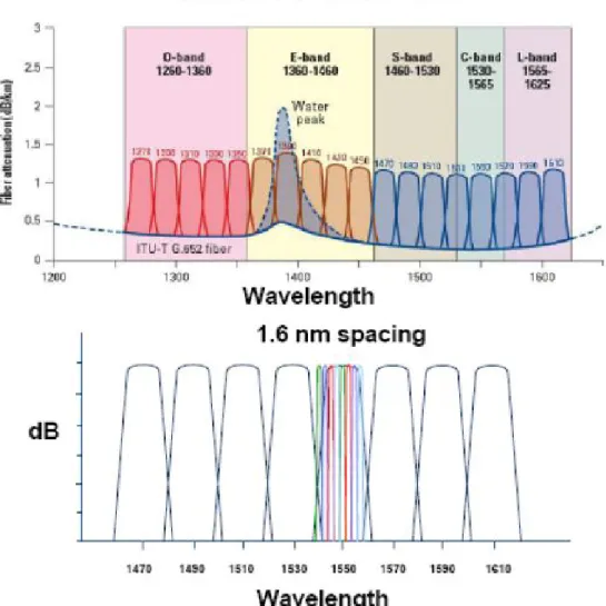
Figure 1.4 – DWDM channels spacing.
The technology described previously is supported with narrow band laser sources which permit to obtain light signals having a very narrow emission band, an high degree of coherence end show a very stable properties.
17
Thus, these kind of laser sources allowed to optimize the channel spacing in optical fiber.
1.1 Multiplation in optical network
The multiplation is a technique that permit to share the available transmission medium with several users [2].
In traditional phone networks which uses an electronic technologies, commonly TDM (Time Division Multiplation) technology of multiplation is used. This kind of multiplation is present also in optical network but shows several problems in term of electronic implementation. Besides, the high channels capacity used in optical network involve that is hard to divide the time slot of right duration for each client. For this reason, other kind of multiplation is used for optical networks.
1.1.1
Multiplation Techniques
There are different multiplation employed in optical network depicted following.
Space Division Multiplexing (SDM) is a way to divide the space offered by a
physical transmission channel (e.g. an optical cable), thus several channels are propagated in different spatial position. Applying this structure in optical case, the multiplation is achieved exploiting different optical fibers deployed in the network. Sometime, not all fibers are used for guarantee the link but a small number of these are used in order to realize a protection and a sort of path redundancy. This kind of multiplation is not expensive and its realization is easy.
18
The disadvantage consist in deploy the optical cable and this is involve several costs for the optical network vendors.
Figure 1.5 – Multiplation techniques used in different layers on an optical network.
Wavelength Division Multiplexing (WDM) is the hinge multiplation of the
optical communications. This kind of concept is based on the idea to transmit several signals into the same optical fiber; each signal is modulated with a particular wavelength.
In optical fiber each wavelength is driven in independent way and, if there aren’t non-linear phenomenon, the different signals are not affected from cross-talking phenomenon. Thus in output from the optical fiber it is possible to separate exactly the incoming signals. The goal of the WDM is that it is possible to transport different modulations format in only one optical fiber. The following picture shows the scheme of an point-to-point optical communication system in which is used WDM technique. Every signals is modulated with different rate and different format and than the
19
multiplexer is able to insert all modulated signals into a single optical fiber.
Figure 1.6 – Principle of WDM multiplation.
A demultiplexer will be able to demultiplate the different received signals in order to give back the right signal to right receiver.
The technology which uses the wavelength division multiplexing has been modified several times in the years.
Figure 1.7 – Point-to-Point transmission system with WDM technique.
In particular, the spacing between the channels has been reduced in order to transport more channels in the same bandwidth.
20
Dense WDM (DWDM) is today used in the long distance backbone networks and has the spacing between the channels varying from 3.2 nm up to 0.4 nm (from 400 GHz up to 50 GHz). Obviously, a system which uses a very small spacing between the channels will employ devices more complex and more expensive in order to have very accurate and cooled lasers and thin filters. Another kind of multiplation consist in Coarse WDM (CWDM) which uses a larger spacing between the channels and this involve the use of not cooled lasers. Then following picture shows the difference between DWDM and CWDM systems.
21
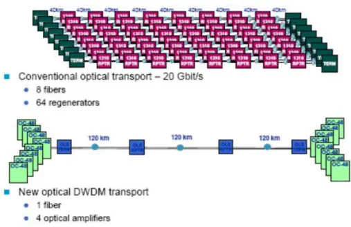
DWDM technique represent a revolution in optical communication word. The picture 1.9 shows the difference between a traditional transmission system compared with a transmission system which uses DWDM multiplation. In order to transport a total capacity of 20 Gbit/s over 360 km, the traditional system required 8 optical fibers, 64 regenerator systems (8 for each fiber) placed every 40 km. The other system, uses only one optical fiber with 4 regenerators placed every 120 km.
Figure 1.9 – Comparison between optical system which uses traditional multiplation and DWDM multiplation.
Time Division Multiplexing (TDM) technique is not often utilized in optical
system but could be convenient use this multiplation in order to further subdivide the single channel managed with DWDM technique already.
22
1.1.2
Network Capacity
The capacity of an optical network assume an important role in order to send the major number of channels in the same optical fiber. Figure 1.10 depict the trend of capacity referred to an optical fiber with the years.
Figure 1.10 – Trend of capacity referred to one optical fiber.
As an example, an optical cable composed by 100 optical fibers is considerate to calculate the total capacity; each fiber transport 64 channels WDM at 10 Gbit/s, thus the total capacity of the cable is equal to 64 Tbit/s. This result show the potential of optical systems.
The figure reported below suggest the relationship between the transmission band and the total capacity. Different transmission systems are depicted, in particular the submarine optical systems uses few band and capacity because the data traffic is narrow with respect a terrestrial system.
23
Figure 1.11 – Transmitted band with respect total capacity for DWDM Systems.
1.1.3
Development of new multiplation technologies
New multiplation technologies are under study in order to improve the today multiplation techniques allowing to obtain the better results.
The first multiplation technology is Polarization Division Multiplexing
(PMD). With this kind of approach, the polarization of the signal is used to
realize the multiplation which is based on the state of polarization that result orthogonal each other. Thus the two orthogonal state of polarization are independent and in this way it is possible to transport two different information without any cross talk effect.
Another kind of multiplation consist in Optical Time Division Multiplexing
(OTDM) which could be exploit to avoid the electro/optical conversion
but this kind of technique result too expensive.
24
Figure 1.12 – Polarization division multiplexing.
Thus Optical Code Division Multiplexing (OCDM) has been studied in order to achieve different codes for each client assuming that, if the codes are not orthogonal the total signal result near to zero value. Unfortunately, also this kind of multiplation result very expensive.
25
1.2 Transport Network
Transport network is composed by several nodes; where the treatment (e.g. the permutation, the extraction and the reintroduction of the signal, the multiplation, and so on.) of the client signal is carried out. In general, the transport network can be divided in three principal parts: access, metropolitan and backbone network [3].
Figure 1.14 - The network configuration.
Transmissive resources of a transport network are suitable to transport all type of client signal (voice, music, images, data and video).
With the introduction of networks liberalization and telecommunication services, transport network operators, now, work in competition with the other ones. Therefore its realization and its management have to reach price, quality and flexibility aim and last, but not least, availability too. Currently operators offer transmissive capacity with different availability (and cost) purposes, divided in classes. Obviously, the network structure
26
(configuration and redundance), the characteristics and the devices technology are employed to the main purposes.
The optical technology is the key element for the transport network realization except for the access network where the use of the traditional twisted pair (copper cable) and other metallic conductor based approaches are still used. Today it is possible foresee the use of the optical technology in the metropolitan network and in the backbone one towards an all optical network, the AON.
1.3 Optical data transmission
Nowadays, to transmit high data rates required from the several end-users, optical technologies are used, because offer high optical frequencies and very broad bandwidths [4]. The wavelength range from 1.3 µm to 1.6 µm, corresponds to a bandwidth as large as 43 THz, unreachable to the other cables technologies. This is the reason why it is easy to understand that the optical fibres allow the use of a very broader bandwidth than the one used for any other electrical cable. In most cases, data transmissions are based on optical media, since the optical fibres allow to guide light over very long distances, presenting low losses. There are also other applications, however, which involve free space data transmission (Free Space Optic), most of all, used in satellite communications, but also to transmit data among buildings where few hundreds meters long distance systems can be quickly installed with low costs. Even an optical transmission system can presents some faults caused by some factors which limit the optical fibres performances. Usually, the bit error rate is strongly dependent on the transmitted signal power, and the received signal must be above a fixed power level established. If the received signal
27
is different respect these rules, a possible error can be easily detected and corrected. The error correction scheme is based on the assignment of more redundancy levels at the transmitted signal, so as to make easier the task of error detection. Additional detrimental influences such as fibre losses or dispersion or non linear effects, which compromise very high distances link, can be moderated increasing the data transmission power.
Nowadays, the application field in which mostly optical fibres are exploited is in long distance networks, but they are also used in few kilometres networks, as phone traffic, Internet traffic and cable TV. In the future, optical fibres will be used in very short distance networks, and, step by step, they will enter in the houses, as it has already occurred in Japan, where many internet connections exploit at all the optical technology.
Recently, the development of the optical fibre technology, has been so fast that there is even the intention of use inter-optical connections inside the super computer to connect several devices.
Current local area networks (LAN) work using electrical cables at data rates of 100 Mbit/s, in spite of 10 Gbit/s, which can be achieved with optical connections.
1.3.1
Single channel system
The devices that transmits the client signal on the optical fibre can be divided in two main classes: the single channel systems and the multichannel systems [5].
The single channel systems, are called also TDM (Time Division Multiplexing) since the transmitted signals are multiplied in the time domain; they transmit only one optical channel on the pairs of optical
28
fibres and this procedure is necessary since the client signals are bidirectional.
The single channel optical systems are composed, as a rule, by a transmitting device, which executes the electro-optical signal conversion, a receiving device, which executes the optical-electric signal conversion, and by a number of optical amplifiers. The number of the amplifiers is variable and it is determined by the network length.
The optical TDM systems employed, are used only on the peripheral networks. The ITU rules indicate a length of 160 Km for the 2,5 Gbit/s systems capacity and a length of 120 Km for 10 Gbit/s systems capacity. The optical technology permits to realize TDM systems without intermediate amplification for special application, for example, the undersea networks.
1.3.2
Multi-channels systems (WDM)
Multi-channels systems, indicated by the acronym of WDM (Wavelength Division Multiplexing), transmit more channels using different wavelength into optical fibre. In these systems, the transmission ends, which outputs have a different wavelength, are followed by an optical multiplexer which multiply all the transmission channels on the same optical fibre. An optical demultiplexer, with complementary function with respect to the optical multiplexer shown in the picture above, divides all the channels according to the wavelengths [5].
29
Figure 1.15 - WDM scheme.
The typical lengths of the amplification sections are of around 80 Km. The regeneration carried out in the receiving devices avoid the degradation effects introduced by fibres, devices and network length.
The spacing channel, in terms of wavelength or in terms of frequency, is different. WDM systems are divided in two main classed:
The DWDM systems (Dense WDM) with channel spacing of 100 GHz in frequency (0,8 nm in wavelengths) and CWDM (Coarse WDM) systems with spacing channel of 20 nm in wavelengths (1600 GHz in frequency).
1.3.3
DWDM systems
Even if DWDM systems has small frequency spacing among channels, are characterized by an high capacity in terms of transmitted channels on the same optical fibre. Typical applications of these systems are backbone networks.
The most spread systems permit the transmission of 40 Channels at 10 Gbit/s spacing of 100 GHz in C band (1530-1565 nm), along 600 Km distance without intermediate regeneration. More advanced solutions are available with 80 and 160 channels at 10 Gbit/s, with spacing lower then
30
100 GHz, which can cover, without electrical regeneration, a very long distance. In particular situations, for example undersea networks, DWDM systems have covered distances of 8000 Km without intermediate electrical regeneration; this result is possible for the particularity environment and for the short section of amplification (50 Km).
DWDM systems can transmit on a single optical fibre data with bit-rate of 1 Tbit/s. Often, a telecommunication cable contains ten optical fibres, so the transmission capacity on optical cables can arrive at 10 Tbit/s.
Now, if the optical cable would casually cut, the consequence for the clients, would be disastrous. For these reasons, is necessary to design networks with high redundancy [3].
1.3.4
CWDM systems
Although the higher spacing among channels, CWDM systems are characterized by a limited number of channels. Such systems are also characterized by a big wavelength range from 1260 nm up to 1610 nm (O+ E + S + C + L band).
The maximum bit rate for the systems is about 2,5 Gbit/s. The maximum lengths are around 80 Km without amplification. For these reasons, CWDM systems are applied in metropolitan networks. CWDM at 16 – 18 channels needs, besides, the availability of the particular optical fibre, which are characterized by a very low loss attenuation.
The most common applications, actually, are limited to 8 channels in the 1460 nm – 1610 nm band. The advantage of CWDM systems is that its cost is lower than DWDM systems, since the high spacing channels allows the use of low-cost devices.
31
1.3.5
OTN - Optical Transport Network
Using the acronym OTN (Optical Transport Network) a step more to all optical network direction has been made.
OTN is composed by optical elements, connected by optical cables. The OTN architecture is composed by three main levels: optical channel, optical multiplation channel, transmission section. Each level has a basic function. For the client signal transmission, OTN is based on three blocks: The first is able to transport signal with bit rate at 2,5 Gbit/s; the second is right for signals from 2,5 Gbit/s up to 10 Gbit/s and the third for signals from 10 Gbit/s up to 40 Gbit/s. These blocks constitute the elements of an optical hierarchy (OTH) which permit the transport of more channels. At the network entrance the transmitter assigns to the channel the right wavelength. This characteristic of the OTN guarantees the high transparency to the client signal in the selected optical channel.
The trame of each of the three kinds of channels is composed by a payload, which contain data, and by an overhead, where all the necessary information to manage the configuration, are contained. With such structure of the optical channels OTN (payload+overhead), all the optical channels are equipped with all the necessary resources for its own management. In this way, the client signal can be transmitted on the optical channels.
An OTN characteristic is the optical transparency, that is network capacity of transport optical signal for long distances through its node without O/E and E/O conversions. This transparency is not total for two reasons: because of the degradation of the optical transmission and because not all the functions are made in the optical domain (that is why are commonly referred as opaque). Today, indeed, are available the devices for the drop
32
and for the optical channel insertion referred as OADM (Optical Add Drop Multiplexer).
The OTN network is composed by transparent optical islands with limited dimensions (100–200 Km), in which, in the near future, optical channels will be always maintained at an optical level, and where all optical regenerators will be adopted.
A considerable enrichment of an OTN is the ASON (Automatic Switched Optical Network), where optical channels routing is intelligent and faster. The ASON permits an elaboration time very small (from 10 ms up to 1 s) and the new routing when the damaged is present. This new network can offer also new services as Bandwidth on Demand and Optical Virtual Private Network.
1.3.6
AON – All Optical Network
The all optical network is the final step of the evolution of the transport network since it permits to remove the electrical regenerator placed in the optical network achieving a total transparency. The evolution of the OTN in the AON permits to create a broad optical island in which the client signal is converted from electrical to optical only in the beginning point and the same signal is converted from optical to electrical format only in the final point. This evolution will be possible when all the network optical elements will be available.
33
1.4 Wavelength Division Multiplexing WDM
The modern technique to transport high amounts of data on optical fibres is called Wavelength Division Multiplexing (WDM). This technique uses optical fibres to transport data and permits simultaneously transmission of more independent channels on the same medium.
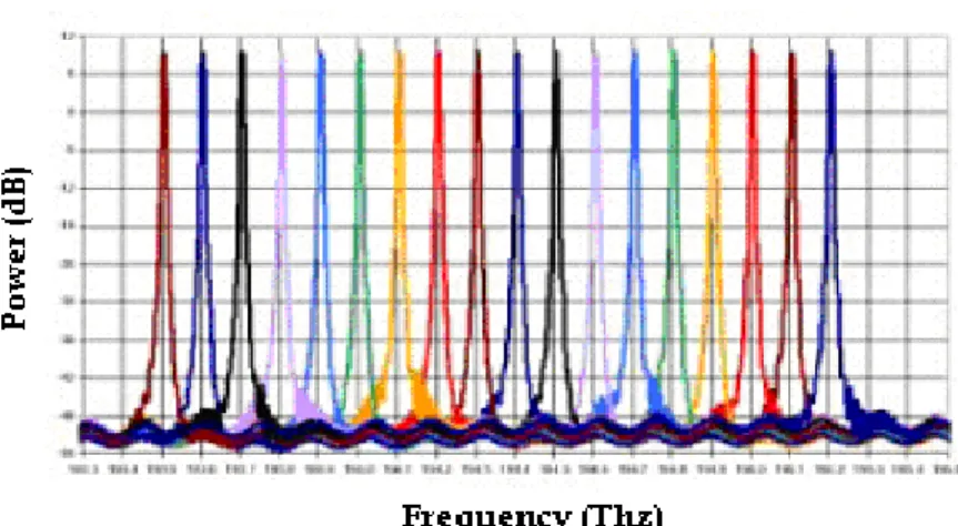
An alternative way to consider WDM is to see it under the point of view of the transmission of several channels, giving to each one a different colour (different wavelength). In this way the transmitted spectrum can be seen as a “rainbow” [5].
Figure 1.16 - WDM system spectrum.
Obviously, the wavelengths taken under consideration, are characterized by frequencies which can not be seen by human eye. Nevertheless, this peculiarity of the wavelength can be exploited to describe such technique in a funny way.
WDM permits to combine more optical channels with several wavelengths, transmitting them together and filtering at the receiving side. Usually, in optical fibres communications, different wavelength
34
channels are transmitted to increase the channel capacity and to create a good data transmission link lowering the per bit costs [6].
Exploiting at the most the optical fibres potentialities with a single channel at high bit rate, very broad bandwidth might be obtained.
However, given the enormous available bandwidth about THz of the low loss transmission window of silica single-mode fibres, this would lead to a data rate which is so much more higher than what can be handled by transmitters and receivers.
Nevertheless the bandwidth given by the optical fibres is very broad, dispersions might have a damaging effect in high distances transmission. WDM is able to solve these problems since maintains the transmission rate of each channel at a low level (e.g. 10 Gbit/s or 40 Gbit/s) and can combine several channels together, giving a total transmission broad bandwidth.
Dense wavelength division multiplexing (DWDM) is characterized by a channel spacing equal to 100 GHz and can be made by using several transmission channels (about 40 or 80 channels), while on the contrary, Course wavelength division multiplexing (CWDM) is usually referred as that systems that works with low channels numbers far away from each other (one, for example, propagating at 1.4µm and the other one at 1.5µm). Moreover, when more channels are transmitted together and suffer some losses, they can be amplified by a single device, since modern erbium amplifiers have a very high amplification bandwidth. Obviously, wavelength division multiplexing, is affected by some problems which can be caused by the interactions of the data channels as the crosstalk and channel interference, or by variation of gain with different wavelength, or again, by non linear effects [7]. Combining together more techniques, essential progress has been made to attenuate these detrimental effects. Furthermore, many fundamental parameters at the basement of the
35
transmission systems must be chosen and varied in a right way to make WDM a complete system for all the performances, and so the services, required by end-clients. These parameters, such as channel spacing, transmitters power levels, fibre and amplifier types, modulation formats, if suitably chosen, permit to satisfy the demand of the client in term of bandwidth and performances.
Since the bandwidth required is increasing and sometimes it can not be foreseen, even in optical fibres link, which use few channels, it is correct to place devices which are able to manage many channels. In fact, often it has been avoided to place additional cables if the bandwidth, required by the clients, increased. In such way, the old systems, no more able to offer all that was required to them, that is high bit rate, have not been substituted but amplified, obtaining the transmission capacity required.
In many cases, TDM can be an alternative to WDM. The TDM technique is based on the concept that different channels are distinguished by arrival time rather than by wavelength.
The modern technology offers several kinds of WDMs. A basic form of WDM can be built using a wavelength around 1300 nm and another one around 1500 nm or utilizing a wavelength couple with values of 850 nm and 1300 nm. This kind of system is realized with few components with low coast (CWDM). The following picture shows an example of a very simple WDM system using multimode fibres [5].
36
In this kind of multiplation, some couplers, having multiplexer and demultiplexer function, are used to mix transmitted signals and to separate the received signals. So it is clear that this system use different bands rather than different wavelengths in the same band.
The scheme shown in the picture, uses separate fibres for each direction, while there are other schemes which use just one bi-directional fibre, used for both data transmission and receiving. Besides, some systems use bands different from the one shown in the picture above.
The most common systems operate at a very low transmission rate, so it is clear that these systems are not employed in the large communication networks. Nevertheless, such systems, which do not offer a very high transmission rate, find application in the transport of video signal for security control.
Another kind of multiplation is the Dense WDM which is an evolved versions of WDM multiplation. This kind of technique allows to transmit so much more channels on the same optical media than the multiplation WDM does.
Figure 1.17 – Dense WDM (DWDM) scheme.
The scheme shown in the figure, illustrate the principle devices used to realize a simple DWDM multiplation. Each channel uses its own wavelength and more channels are multiplated in the same optical media,
37
besides the wideness among the channels can be 1 nm. The width of the channels depends on many factors such as the stability and the tolerance of the laser sources used, the kind of modulation and the performances of the other optical devices employed in the general system.
In general, the WDM system, is constituted by some key parts which have the task of generate, transmit and receive the client signal. Very often, occurs that the transmitting source is a laser which must have a very narrow line-width to leave the signal in the allocated band.
The next step is to mix more channels together using different wavelength. There are more ways to combine these channels; the most simple is to use a coupler which couple, each time, the channels. The coupler presents a loss of about 3dB and such loss occurs at each stage in which the two channels have coupled.
It is clear that, if an high number of channels is used, the initials loss result too much high and this yields to use more amplificatory stages to compensate the losses.
Therefore, it can be easily understood that a coupler can be used to achieve the WDM scheme only if few channels have to be transmitted. Gratings and planar waveguides have very lower losses which do not depend on the number of channels. This is the reason why they are very often used in systems transmitting much more channels. After having combined the signals in the right way, they have to be transmitted through only one optical medium.
During the transmission, among adjacent channels some effects can be generate such as the crosstalk and the Four Wave Mixing (FWM) which lower the performances of the whole system. By controlling the channel spacing and the transmitted power levels, the crosstalk effects provoked can be minimized; besides some techniques, which allow to establish exactly the channel spacing, can be adopted to completely remove the non
38
linear effect FWM. Another fundamental aspect is the amplification that the transmitted signals have to undergo on long haul transmissions. The amplifier skill to amplify simultaneously more multiplated channels make possible to realize the WDM multiplation among long distances.
Nevertheless, when several amplifiers are used together, especially in long distances networks, their noise (Amplified Spontaneous Emission - ASE) are add up together causing great difficulties.
Once a time that the signal is arrived to the receiver, the various channels transmitted have to be separated, assigning to each client the respective data traffic. This is a very difficult operation and different techniques can be used to realize it. Reflective grating, splitters or waveguide grating routers can be used.
To receive the transmitted signals, common detectors are used and they are applied also in other circumstances since the signal has been already demultiplated. It is clear that each channel data rate is independent from the other channels; that means that a channel can have a rate of 2.5 Gbit/s, while another one can run at 622 Mbit/s and the last group of channels can run at 200 Mbit/s.
39
1.5 WDM systems - The limitative factors.
As it has been seen up to now, WDM multiplation allows to transmit more channels together in a very profitable way on the same optical fibre [8]. Nevertheless, some factors which limits the performances of this technique, especially in long distance network, does exist. Fibres non linearities, amplifier spontaneous emission (ASE) and chromatic dispersion can be taken as example; besides some of these can induce the distortion of the transmitted signals.
Since networks are usually very long, a series of cascading amplifiers will have to be used.
Obviously, when a channel wavelength is centred with the optical amplifier gain peak, the optical SNR of that channel will be increased respect to the other channels; this involve that a channel with a SNR very different from the other channels, make possible the non equalization of the channels with a consequent decrease of transmission performances. Another factor in long distances transmissions which has not to be undervalues is FWM effect which strongly limits system performances. When several waves having different wavelength are transmitted, they interact giving rise to new pulses placed at different wavelengths. These new pulses are commonly called replica which can become very dangerous since they take away energy from the signals which have to be transmitted. Follow, is presented a picture which depict this kind of non linear effect when three channels are used.
40
Figure 1.18 – Generation of FWM effect using three channels.
The picture shows FWM effect produced by the interaction of three signals co-propagating in an optical fibre. Generating these replica, the power level of the three signals is affected and time interactions between other co aligned channels (in a WDM scenario) are strongly enhanced. Therefore, it is necessary to limit or remove such effect to increase the WDM transmission system performances. Another example of FWM effect is shown in the following picture. Here only two signals are transmitted on the optical fibre. In particular conditions, these signals, can generate more replicas which degrade the data signals.
41
1.6 Protection techniques in WDM systems
A more important aspect of the wavelength division multiplexing is the protection and the technique used to make this kind of multiplation very safety [9].
In fact, the interruption of the optical connection which work at high bit rate (for example 10 Gbit/s or 40 Gbit/s), even only for a few seconds, provokes a high data loss. For this reason, the telecommunication management which use this technology, must guarantee at the final client a limited out-of-service time and fast network recovery. In the past, if a damages which occurred in the optical networks resulting worked out, a routing from damage connection to the operated link was done. Nowadays, this should be unthinkable because the optical network worked out should be considered insecure and vulnerable. Moreover, the damage management and the data re-direction is carried out by an operating central which make these choices in the distance. The management will not accept a transmission data system without protection but will consider a networks which routing automatically the connection when a damage is present.
The optical networks commonly used are systems based on a layer architecture. The function of WDM layer is the provisioning of the connectivity and of the band needed. This service realizes the point-to-point required connection achieving the point-to-point-to-point-to-point optical link. These circuits are called light-path and are composed by a number of channels WDM which transport the data from the source node to the destination node. Each light-path have a data flow with high bit rate which is inserted and extracted by the optoelectronic interface between the WDM layer and the upper one. The WDM layer is divided in more sub-layers to realize in
42
a more simple way the function as the light-path control or the routing band the wavelength assignation, error detect (fault recovery) and signal management in the optical network. The sub-layers of the WDM layer are called optical channel sub-layer, optical multiplex sub-layer, physical media sub-layer and optical transmission sub-layer. The first layer provides for the routing and the wavelength assignation, for fault recovery and for the connections control. This layer check also the light-path.
Each link is managed by the optical multiplex sub-layer, thus local resources check is possible. The optical transmission sub-layer, in the end, manages all the control functions of the transmission devices as the amplifiers and the regenerator.
1.6.1
Protection technique in WDM layers
Optical channel sub-layer or optical multiplex sub-layer (OMS), are two layers where is possible to adopt the protection technique. In the first case, the light-path is protected, for this reason this case is called path protection. In case of damage, each introduced data is routed on another protected light-path; this is defined working, while the light-path used before the damage is called protection.
In the second case, the transmitted WDM channels are protected; this protection is a local function carried out by the OMS devices which constitute the single link.
The channels multiplexed are routed on another link, if the damage is present, without data loss. The substantial difference between the two technique is that the second is able to treat simultaneously all the damaged light-paths, while the first can operate on the single light-path.
43
The traditional WDM networks are based on an optical cable composed by couple of fibres and each of them permits the propagation in a single direction. The OMS protection modality utilize four optical fibres to each link; besides, the fibres couple normally are utilized for the data transmission. In this case is placed another fibre which is called backup and permits to route the data in case of damage. A second modality which use a single fibres does exist, and in case of damage one direction is used to transmit half WDM channel and the another half is used for protection task. To manage the protection resources, two solutions are possible and these solutions are very different. The most common technique is called
preplanning in which, first of all, the protection resources are allocated. The
tasks carried out by the network devices to obtain the data protection are very simple because the network has been already treat. These reasons allow a very fast recovery but the resources are destined to a stiff way. The other solution is called provisioning which involves the over-size of the network even if the data required are lower then the real network dimension. This implies that in case of damage, the network can re-allocate the new connection in a dynamic way always obtaining new resources. Another advantage is the possibility to guarantee the total security even in case of many simultaneously damages as, for example, the environmental disaster.
This is, on the contrary, the dynamic way which result more complex to manage but this is the solution more suitable especially in this time in which the phenomenon of IP over WDM is very important.
44
Chapter 2
Introduction: 2R all optical regeneration – state of the
art.
Different way to obtain all optical regeneration of signal are presented in this section. Several techniques are described in order to evaluate and characterize the differences that exist between the mentioned approach. There are two big categories: Single-channel regeneration, in which different ways to obtain the regeneration are implemented exploiting, for example, the non linearity offered by the optical medium. Moreover, this kind of approach is applied to one channel only, thus if several channels needs 2R all optical regeneration, the regenerator is applied to each channel.
For this reason, new kind of systems are under study in order to manage several clients using only one optical regenerator system for all end-users. These are the second category: Multi-channels regeneration. In this way it is possible maintain low the cost per bit and also to guarantee low power consumption using less devices whit respect to the single channel systems. Following are described some techniques used from single channel system but also the 2R all optical regeneration system used for multi-channels regenerations. Multi-channels regenerator permit to employ the reshape system in WDM or DWDM scenario because are able to manage several channels at the same time offering also a wavelength conversion.
45
2.1 Single channel regeneration
The single channel systems have been a first step towards the introduction of optical communications backbones. The fundamental problem was constituted by the continuous conversion of format which slowed down the transmission speed. By introducing all optical regenerators in the networks, this problem has been exceeded, guaranteeing very fast signals elaboration.
2.1.1 2R Optical regenerator based on interferometric structures
The interferometric structures, used in order to obtain some 2R regenerators, can be grouped in the two big categories of the interferometers: Sagnac and Mach-Zehnder.
Sagnac interferometer is composed by a bidirectional coupler to whose output doors are connected the ends of one optical fibre.
Figure 2.1 – Schematic structure of Sagnac interferometer.
Even if the fibre constitutes a loop, feedback mechanisms do not take place and, therefore, all the input light exits from the interferometer after a complete turn. The input signal with power Po is divided in two
counter-46
propagating signals, which, after a complete turn in the fibre loop, interfere giving back in output the two signals Pr and Pt:
0 1 cos 2 r p p 0 t r p p p .
The difference of phase depends on the non linearity by the two counter propagating signals. Different Sagnac interferometer can be obtained: NOLM (Nonlinear Optical Loop Mirror), is an interferometer where a piece of fibre exploit the non linear effect; SLALOM (Semiconductor Laser Amplifier in a Loop Mirror), where the non linearity is generated by inserting in the interferometer loop a semiconductor amplifier working in a non linear conditions.
The Mach-Zehnder interferometer is composed by an input and an output couplers, connected by two passive waveguides constituted of Lithium Niobate. Also in this case the input signal can be split in two parts interfering at the output coupler in accordance with the different distortion suffered through the two passive waveguides.
47
In both cases a right phase-difference of the two fields concentrates all the power on a single output branch of the interferometer and the device has a transfer function able to suppress the noise, regenerating the input signal.
2.1.2 2R Optical regenerator based on NOLM
A generic pulse signal, which arrives at the input coupler, is divided in two components travelling in the loop in a counter-propagating way and showing different peak powers depending on the couple relationship [10].
Figure 2.3 – NOLM Scheme.
After a complete loop, the components have different phases out,
constituted by a linear term determined by the fibre length covered, and a non linear one, determined by SPM and XPM phenomena which is present during the propagation. Being the linear term the same for both components, their relative phase-displacement depends on the non linear term. In 0.5 case, also the non linear phase-displacement is null and the two components, interfering in the coupler, recombine themselves in phase, giving back a signal equal to the input one, that is pr p0. The
interferometer behaves like a perfect mirror. For 0.5 case, out values do exist, for this p r 0 and pt p0, that is all the input power is
48
transferred by the interferometer on the other branch of coupler input-output. The interference generated at the end of the ring depends on the phase difference existing between the two components, which, in its turn, depends on their power difference, determined by the couple relationship . Increasing the input power level, the output power increases but in a non linear behaviour. The non linear input-output characteristic shows a flat area. Working around these powers it is possible to reduce the signal amplitude noise, obtaining a regenerated signal. In fact, Sagnac interferometer is able to reflect the low power and transmit the high intensity radiation, reducing, in such a way, the noise level. The NOLM is a passive regeneration device, able to operate on different wavelengths signals and with a speed of answer around the femto second. Besides, the NOLM device require powers and fibre length such to induce non linear effects; these parameters depend on the kind of fibre used.
2.1.3 2R Optical regenerator based on SLALOM
In the same way, NOLM device has the input signal in the loop which is divided in two parts through an input coupler. A part travels the loop clockwise and reaches the SLA first, in which it is linearly amplified.
49
The part of signal that travels counter-clockwise, reaches the SLA in a T time, after the signal travelling clockwise, facing a different amplifier gain. This gain depends on the saturation imposed by the signal travelling clockwise and by the recovery times , in terms of bearers in conduction band, of the same amplifier. The two pulses interfere in the coupler producing an output signal depending on the phase difference and gain experimented in the loop by the two input signals. The pulse is re-shaped according the interferometer functioning principle. Respect to the NOLM, the SLALOM has two advantages: compactness and lower optical power demand. In the NOLM, in fact, powers of the order of W are necessary in order to activate the Kerr effects which generates the non linear phase-displacement. Moreover, the optical fibre, in which such effects verify, must be sufficiently long in order to allow the effect efficiency. In order to carry a semiconductor amplifier in a non linear zone, powers of the order of tens mW, are sufficient. Moreover, the effect is concentrated in the same amplifier and for this the unique optical fibre piece used is the one for the amplifier connection with the coupler. The processing speed is slower (some GHz against the THz of the NOLM).
2.1.4 2R Optical regenerator based on SOA-MZI
The regenerators based on interferometric structures, such as Mach-Zehnder type, are ultra-fast devices but, at the same time, they depend on the input pattern, for the SOA intrinsic characteristics [11]. They allow the contemporary conversion of wavelength and modulation format, passing from NRZ to PRZ (pseudo RZ). Two families of devices can be observed: one based on interferometric structure, with two identical SOAs on the branch of the interferometer; the other with a monomodal SOA on a branch and a multimodal SOA on the other branch.
50
In the case on the left side, in both the SOAs the low power clock signal and the data signal enter in the device.
Figure 2.5 – Interferometric structure with equal and different SOA.
Until the two SOAs are crossed by the clock signal, and therefore they are not saturated, this last join itself again at the Mach-Zehnder output, reproducing the logical level zero [12]. When the data signal reaches one of the two SOAs, the interferometer overbalances and, at output coupler, the logical level “one” is created. When the signal reaches also the second SOA, the interferometer balances itself again and the logical level zero is produced. The signal reshaping mainly happens at the logical level one, thanks to the sinusoidal transfer function of the device, while the improvement of the extinction relationship is rather poor, around 4 dB. This device is based on the processes of Cross Gain modulation (XGM) and Cross Phase Modulation (XPM). In the XPM case, the loss balance of the device depends on the difference between the two SOAs. The multimodal SOA has active area more width and, consequently, the saturation power is considerably higher, while it is possible to obtain the same gain not saturated. That implies, in addition, that the logical level low is obtained. The consequence, is that the variation of the phase difference between the two branch is realized more quickly in the first case and that the transitions between the two logical levels can happen in short
51
intervals, fallowing higher bit-rate. For equal bit-rate, better regenerating behaviours are obtained.
2.1.5 2R Optical regenerator based on Q-switched laser
An alternative to the interferometric structures, up to now analyzed, is constituted by the Q-switched laser. This laser is made by an integrated passive section between two DFBs: one along 200 µm and one along 350µm, which shows like a dispersive reflector. A shorter DFB section has a bias current such as the region behaves as a laser emitting a continuous that travels in section two and it is back-spread by the reflector (section three in the next figure).
Figure 2.5 – Q-switch Laser.
The combination of sections two and three allows to control the back-spread light in amplitude and phase. The cavity laser made by the three regions emits or not on the basis of the existing interference between the light back-spread and that emitted by region one. By the fact that the quality (Q) of the resonator, constituted by the three sections, influences the activity of the laser, this is the reason why of the device name. The
52
three sections are controlled in current: the current of section two is tied to the refractive index of such region and, therefore, it controls the signal phase passing in the same region; the current of the first section is tied to the wavelength of emission. Its variation influences also the phase relation existing between the optical beam emitted by the first DFB and the one back-spread by section three; therefore, its variation generates a power difference in output from the cavity. If an optical signal is sent into the cavity, the devices can be used as decision element. The optical signal injection in the region laser of the device, in fact, increases the refractive index of this section, generating a variation of its wavelength of emission and consequently generates a variation of the spectral correlation of the cavity. The signal which has to be re-shaped can be introduced through a circulator which collects at the output, the re-shaped signal, thanks to the non linear transfer function shown from the device.
2.1.6 Optical regeneration exploiting Quasi-Continuous
Filtering technique.
This kind of optical regeneration is based on quasi-continuous filtering technique. It is composed by a sequence on N samples of non linear optical fibres divided by filtering optical devices where the central frequency changes gradually along the length of the regenerator [13].
53
Referring to the picture 2.6, each optical filter which is moved a little in term of frequency with respect the previous filter, reduce the spectral band of each section.
As result of quasi-continuous filtering (QCF) technique, the pulse spectral band is strongly reduced. For low intensity signals, the spectral broadening is small and the noise is subsequently attenuated from the other following optical filters; for high intensity signals, the self phase modulation (SPM) induces a spectral broadening and this permit the signals to go through the low loss of the filters. In this way, the amplitude of the signals result reshaped; thus the noise present in the zero level and the amplitude fluctuation of the mark level are either reduced.
Figure 2.7 – Optical eyes after transmission with and without regeneration.
Referring to picture 2.6, each optical fiber is 200m long, has γ= 13 w-1 km-1
and α= 0.2 dB/km. with these parameters, the system shows the ability to regenerate the noisy signals. In particular, the picture 2.7 shows a regenerated signal after 3000 km and 6000 km. A comparison with non regenerated signal is depicted too.
54
2.1.7 Mamyshev 2R regenerator.
Mamyshev 2R regenerator is an all optical system able to manage and regenerate optical signal used in optical communication in order to obtain an all optical data elaboration. In 1998, the researcher Pavel Mamyshev of Bell Labs, suggested the adoption of the non linear effect, in particular self phase modulation (SPM) used for single channel optical signal, obtaining the re-amplification and the re-shaping at the same time and all in optical domain [14].
The design of the regenerator mainly consist of a sample of high non-linear fiber with a band-pass filter (BPF). This is the main configuration which is repeated more time if the system required high performances of regeneration.
The modulated optical signal (for example NZ or NRZ format) run through a few km of non linear optical fiber and the signal is spectrally broadened due to self phase modulation, thus SPM broadens the signal spectrum with the pulse intensity. Then, the BPF which has a fixed spectral bandwidth, is able to filter the noisy signal giving back a reshaped signal. In this way the filtering behavior is inside the SPM effect; for low signal (“zero” level) which has low intensity do not broaden significantly and is out of the BPF, thus the output zero signal is compress towards the zero level.
When “one” level is present, the signal intensity is sufficiently strong in order to broaden the spectra of the signal by the SPM, thus sufficient portion of the signal run trough the filter giving back a regenerated signal corresponding to high part (one level) of the signal.


![Fig. 3.6 shows that to each replica corresponds a particular transfer function able to compress the noise present on the signal [29]](https://thumb-eu.123doks.com/thumbv2/123dokorg/7610349.115210/74.892.253.677.127.372/replica-corresponds-particular-transfer-function-compress-present-signal.webp)
