UNIVERSITY
OF TRENTO
DIPARTIMENTO DI INGEGNERIA E SCIENZA DELL’INFORMAZIONE 38123 Povo – Trento (Italy), Via Sommarive 14
http://www.disi.unitn.it
DESIGN OF A MINIATURIZED PLANAR ANTENNA FOR FCC-UWB COMMUNICATION SYSTEMS L. Lizzi, F. Viani, R. Azaro, and A. Massa
July 2008
Design of a Miniaturized Planar Antenna
for FCC-UWB Communication Systems
L. Lizzi, F. Viani, R. Azaro, and A. Massa
Department of Information and Communication Technology University of Trento, Via Sommarive 14, 38050 Trento, ITALY
E-mail: [email protected]
Abstract – In this letter, the design of a planar antenna compliant with FCC requirements for ultra-wideband (UWB) transmission systems is described. With reference to a planar geometry on a dielectric substrate, the shape of the antenna is described by means of a spline-based representation and it is determined by means of an optimisation process aimed at finding the optimal descriptive parameters that allow to fit the user-defined electrical and dimensional requirements. The reliability and effectiveness of the antenna prototype are assessed through simulations as well as experimental measurements.
Introduction
Recently, UWB technologies have attracted a lot of attention in several applicative areas and, in particular, in wireless communications. The design of the antenna device is one of the most challenging tasks for the design of an efficient and reliable UWB system. As a matter of fact, because of the power limits of UWB systems [1], an UWB antenna should be highly-efficient and non dispersive to allow a high transmission rate. The synthesis becomes more and more complex when an integration of the antenna in a portable or miniaturized device is required. In recent years, various shapes have been
studied and proposed to build UWB antennas suitable for different purposes and applications. Simple geometries have been assumed as reference shapes to design UWB antennas (e.g., triangular [2], circular disk [3], annular ring [4], rectangular [5], diamond [6] and bow-tie [7]). However, canonical geometries are characterized by small numbers of degrees of freedom and the optimisation, aimed at fitting suitable electrical parameters, is limited to few parameters. A possible solution to overcome such an intrinsic limitation is adopting more complex geometries with more degrees of freedom. As a matter of fact, they might be tuned to match multiple and different requirements guaranteeing and optimal trade-off also in the presence of contrasting needs. Obviously such an approach implies to solve a complex synthesis problem that cannot be afforded with classical design procedures. In this letter, the synthesis of a planar UWB antenna is addressed by considering a spline-based representation [8] of the antenna shape and it is solved by means of an efficient multi-agent optimization strategy [9].
UWB Antenna Design
For the synthesis of the UWB antenna, the following constraints have been considered: a) a maximum size of 5×5
[ ]
cm2 on an Arlon dielectric substrate (thickness h=0.8[ ]
mm , εr =3.38, tgδ =0.0025 at f =10GHz); b) a working frequency band in the range f ∈[
fmin,fmax]
, being and; c) impedance matching at the input port (i.e., amplitude of such that GHz fmin =4 GHz fmax =9 s11
( )
f dBs11 ≤−10 , f ∈
[
fmin,fmax]
; d) flatness of the amplitude of the transfer function by considering a pair of identical antenna (i.e.,[f f ]s
( )
f f [f f ]s( )
f dB f 6 min max 21 , 21,max min max min
− ≤ −
∈
∈ ; e) linearity of the phase of the transfer function; f) a hemispherical coverage. The reference geometry has been described by means of a spline curve with N =7 control points
[8] and by the half-width of the input section of the antenna. Moreover, the reference shape has been equipped with a rectangular ground plane to be dimensioned, as well, in order to complete the antenna description. The synthesis of the antenna has been formulated as an optimisation problem by considering the design requirements as problem constraints. The unsupervised synthesis has been implemented by integrating the PSO algorithm [9][10] with a spline generator and a MoM [11] electromagnetic simulator to evaluate the electric behaviours of the trial solutions iteratively generated according to the PSO strategy. As far as the ranking of the trial solutions is concerned, a cost function has been defined. More in detail, it is the sum of three terms, each one accounting for the difference between requirements and estimated performances/features (e.g., radiation pattern, impedance matching, size, etc...) of the trial shapes of the antennas. The procedure iterated until a maximum amount of iterations has been performed or the cost function value reached a user-defined threshold.
(
P1,.P2,...,P7)
Numerical Results and Experimental Validation
According to the approach summarized in the previous section, a solution compliant with the design constraints has been obtained after PSO iterations. As regards to the PSO setup and according to the guidelines in [9] [10], the following configuration of parameters has been adopted: trial
25 = opt K 6 = R
solutions, a cost function threshold fixed to , and a maximum number of iterations equal to . The synthesized geometry is shown in Fig. 1 where both the control points
5 10− = η 1000 = K
(
P1,.P2,...,P7)
of the spline representation andthe others descriptive parameters
(
ϕ1,ϕ2,ϕ3,ϕ4)
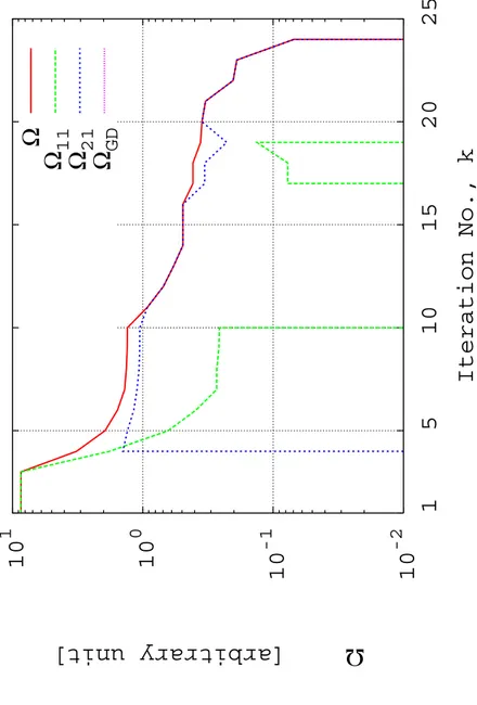
of the antenna shape are shown, as well. In Fig. 2, the plot of the cost function Ω versus the iteration index is reported. As it can be observed, the cost function is composed by three different contributions. The former Ω is related to the condition on the 11amplitude, while and 11
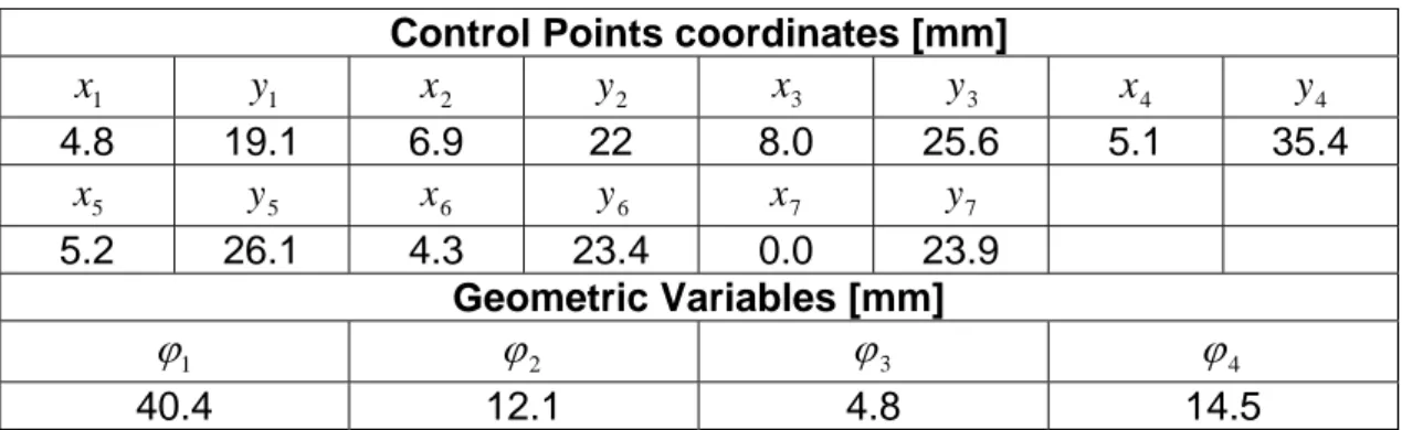
s Ω21 Ω are concerned with the amplitude and GD phase of , respectively. The convergence values of the descriptive parameters of the synthesized antenna are given in Tab. I. The antenna prototype (Fig. 3) presents a maximum size of dimension equal to
21 s
[ ]
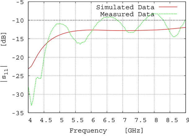
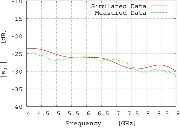
2 4 . 40 2 .24 × mm . In order to assess the effectiveness of the antenna in an UWB system, two samples of the antenna have been built by using a photolithographic printing circuit technology. The experimental assessment has been carried out in an anechoic chamber with the prototypes placed at and fed through a rigid coaxial cable soldered at the input port of the antenna as shown in Fig. 3(b). The values of the scattering parameters have been measured with a vector network analyzer by considering the input port of the antenna as reference section. The plots of numerical and measured values of the amplitude of are reported in Fig. 4. As it can be noticed, besides a good agreement between measurements and simulations, the synthesized solution fits the impedance matching requirements. In Fig. 5, and Fig. 6, the comparison is concerned with the parameter. As expected (from the simulations), the range of variation in the FCC-UWB frequency band
] [ 150 mm d = 11 s 21 s
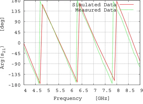
does not exceed 6 dB (Fig.5). Moreover, both simulated and experimentally-collected values shown in Fig. 6 assess the linear behaviour of the phase of
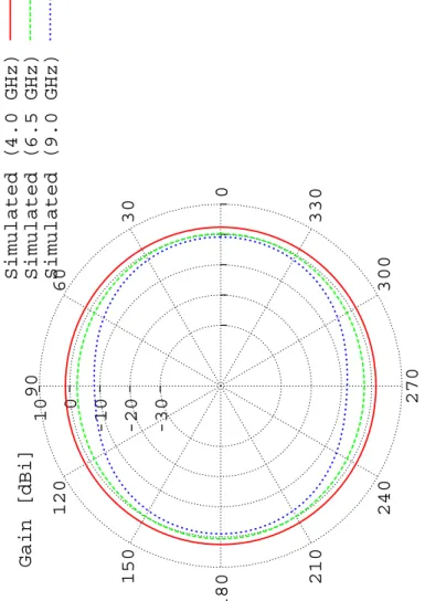
. Because of the relationship between the phase and the group delay, such a phase trend implies a maximum variation of the group delay equal to . Finally, the compliance of the radiation properties of the synthesized antenna can be verified in Figs. 7–9, where the plots of the radiation patterns in the horizontal plane (Fig. 7) and along two representative vertical planes (Figs. 8-9) are shown.
21 s s21
[
sec 18 . 0 n]
ConclusionsIn this letter, the design of an FCC compliant UWB antenna working in the band has been described. Given a set of electrical and geometrical design requirements, the descriptive parameters of a spline-based reference structure have been synthesized by means of an efficient optimization strategy. The synthesized antenna has been assessed both numerically and experimentally by using a pair of antenna prototypes built according to the results of the synthesis process.
GHz
9 4÷
Acknowledgments
The authors wish to thank very much Ing. Alessandro Frattoni (Selex Communications) for his help in the experimental assessment of the antenna prototypes. This work has been partially supported in Italy by the “Progettazione di un Livello Fisico ‘Intelligente’ per Reti Mobili ad Elevata Riconfigurabilità”, Progetto di Ricerca di Interesse Nazionale – MIUR Project COFIN 2005099984.
References:
1 Federal Communication Commission: First Report and Order, “Revision of part 15 of the commission's rules regarding ultra-wideband transmission systems”, FCC 02-48, Apr. 2002, [Online]. Available: http://hraunfoss.fcc.gov/edocs_public/attachmatch/FCC-02-48A1.pdf 2 C. C. Lin, Y. C. Kan, L. C. Kuo, and H. R. Chuang, A planar triangular
monopole antenna for UWB communication, IEEE Microwave Wireless Comp. Lett. 15 (2005), 624-626
3 J. Liang, C. C. Chiau, X. Chen, and C. G. Parini, Study of a printed circular disc monopole antenna for UWB systems, IEEE Trans. Antennas Propagat. 53 (2005),3500-3504
4 Y. Ren and K. Chang, An annular ring antenna for UWB communications,” IEEE Antennas Wireless Propag. Lett. 5 (2006), 275-276
5 J. Yung, W. Choi, and J. Choi, A small wideband microstrip-fed monopole antenna, IEEE Microwave Wireless Compon. Lett. 15 (2005), 703-705
6 G. Lu, S. von der Mark, I. Korish, L. J. Greenstein, and P. Spasojevic, Diamond and rounded diamond antennas for ultrawide-band communications, IEEE Antennas Wireless Propag. Lett. 3 (2004), 249-252
7 K. Kiminami, A. Hirata, and T. Shiosawa, Double-sided printed bow-tie antenna for UWB communications, IEEE Antennas Wireless Propag. Lett. 3 (2004), 152-153
8 C. De Boor, A Practical guide to spline. Springer - New York, 2001
9 J. Robinson and Y. Rahmat-Samii, Particle swarm optimization in electromagnetics, IEEE Trans. Antennas Propagat. 52 (2004), 397–407 10 R. Azaro, F. De Natale, M. Donelli, A. Massa, and E. Zeni, Optimized
design of a multi-function/multi-band antenna for automotive rescue systems, IEEE Trans. Antennas Propagat. 54 (2006), 392-400
11 R. F. Harrington, Field computation by moment methods. Robert E. Krieger Publishing Co. - Florida, 1987
Figure Captions
Fig. 1 Antenna geometry and descriptive parameters. Front view (a) and
back view (b)
Fig. 2 Behaviour of the cost function during the iterative synthesis
procedure
Fig. 3 Prototype of the FCC compliant UWB antenna. Front view (a) and
overview (b)
Fig. 4 Comparison between simulated and measured s11 amplitudes
Fig. 5 Comparison between simulated and measured s21 amplitudes
Fig. 6 Comparison between simulated and measured s21 phase values
Fig. 7 Radiation patterns in the horizontal plane
Fig. 8 Radiation patterns in the φ = 0° vertical plane
Table Captions
Tab. I Values of the descriptive parameters of the UWB antenna
y x z ϕ1 ϕ2 ϕ3 P4 P2 P3 P5 P1 P7 P6 y ϕ1 z ϕ2 x ϕ4 (a) (b)
10
-210
-110
010
125
20
15
10
5
1
Ω [arbitrary unit]
Iteration No., k
Ω
Ω
11Ω
21Ω
GD(a)
(b)
-35
-30
-25
-20
-15
-10
-5
4 4.5 5 5.5 6 6.5 7 7.5 8 8.5 9
|s
11| [dB]
Frequency [GHz]
Simulated Data
Measured Data
-40
-35
-30
-25
-20
-15
-10
4 4.5 5 5.5 6 6.5 7 7.5 8 8.5 9
|s
21| [dB]
Frequency [GHz]
Simulated Data
Measured Data
-180
-135
-90
-45
0
45
90
135
180
4 4.5 5 5.5 6 6.5 7 7.5 8 8.5 9
Arg(s
21) [deg]
Frequency [GHz]
Simulated Data
Measured Data
10 0 -10 -20 -30 Gain [dBi] 0 30 60 90 120 150 180 210 240 270 300 330
Simulated (4.0 GHz) Simulated (6.5 GHz) Simulated (9.0 GHz)
10 0 -10 -20 -30 Gain [dBi] 0 30 60 90 120 150 180 210 240 270 300 330
Simulated (4.0 GHz) Simulated (6.5 GHz) Simulated (9.0 GHz)
10 0 -10 -20 -30 Gain [dBi] 0 30 60 90 120 150 180 210 240 270 300 330
Simulated (4.0 GHz) Simulated (6.5 GHz) Simulated (9.0 GHz)
Control Points coordinates [mm] 1 x y 1 x 2 y 2 x 3 y 3 x 4 y 4 4.8 19.1 6.9 22 8.0 25.6 5.1 35.4 5 x y 5 x 6 y 6 x 7 y 7 5.2 26.1 4.3 23.4 0.0 23.9 Geometric Variables [mm] 1 ϕ ϕ2 ϕ3 ϕ4 40.4 12.1 4.8 14.5