•
Detcnninistic safety analysis of Station Blackout postulated accìdent on
the basis of the SMR simulator MASLWR
Descrlttori
Tipologia del documento: Rapporto tecnico
Collocazione contrnttunle: Accordo di programma ENEA-MSE: tema di ricerca "Nuovo nucleare da fissione"
~l'golllCl\ti trattati: Sistemi nucleari innovati
Simulazione numerica con codice di sistema RELAP5
Analisi di sicurezza
lSommario
iL'attività riguarda la simulazione di un progetto di reattore modulare integrale di piccola taglia moderato e 'efrigcrato ad acqua leggera. Due sono i principati obblettivi perseguiti: l) la qualifica del modello RELAP5IMod3.3 utilizzato per le simulazioni e 2) alcuni studi preliminari riguardanti la risposta del progetto di
impianto ad un ipotetico scenario di station blackout.
Il documento si articola in sette capitoli di cui il primo, introduttivo, riporta l'ambito nel quale l'attività va inquadrata, gli obiettivi e la struttura del presente report. L'ultimo capitolo riguarda le osservazioni conclusive ~ell'attività svolta. Il secondo ed il terzo capitolo si focalizzano sul progetto del reattore modulare integrale di
iiccolo taglia preso a riferlmeuto (MASLWR) esuli 'apparecchiatura sperimentale progettata, costruita ed esercita
!ad Oregon State Univerlsty (OSU), che ne rappresenta il modello scalato (l :254 in volume). Il quarto capitale
~escrive il modello messo a punto con il codice RELAP5/Mod3.3 per la simulazione dell'apparecchiatura
sperimentale. I risultati della simulazione dì due transitori (circolazione naturale e lossoffeed waterflowi sonc stati ottenuti sulla base delle specifiche dei due test e, successivamente, confrontati COli i dati disponibili messi a
Idisposizione da OSu. L'analisi dei risultati (riportata nel capitolo quinto) ha consentito di dimostrare che il
odice ha la capacità di predire i fenomeni tenuoidraulici rilevanti e di concludere sulla sua affidabilità delle
simulazioni relative ad un ipotetico transitorio di statico blackout. Pertanto il modello RELAP5 è stato impiegato
per effettuare alcune investigazioni deterministiche di sicurezza relative alla riposta del sistema OSU-MASLWR a fronte di UIlO station blackout completo. I risultati preliminari consentono di dimostrare la potenzialità di tale
irogetto a resistere per oltre 7 giorni in completa assenza di potenza "onsite" ed "offsite", grazie alla relativa
bassa densità di potenza e grande riserva d'acqua.
Note
k;opia n.Incarico a:
INOME FIRMA ~MISSIONE
A. DelNeva Ir.Agpstjni IP.Meloni
DATA 14/0912012
FIRMA NOME
E
XECUTIVE SUMMARYThe aim of the activity is related to the simulation of a small modular reactor (SMR) design, cooled and moderated with light water and having an integral primary system layout. Two main objectives have been pursued: 1) the qualification of a RELAP5/Mod3.3 nodalization used for the numerical simulation of the system and 2) deterministic investigations related to the capability of this small modular reactor design to cope with a station blackout postulated accident scenario.
The report is divided into seven sections. Among these, the first provides the framework of the activity, the objectives and the structure of the report and the last describes the main conclusions. The second and the third sections are focused on the brief description of the reference reactor design (i.e. MASLWR) and on its scaled down (1:254 in volume) experimental facility, designed, constructed and operated at Oregon State University (OSU). The forth section reports the main features of the nodalization set up for RELAP5/Mod3.3 code. The main results of two blind simulations (natural circulation and loss of feed water tests) are reported in section fifth. The analysis, based on the comparisons with the experimental data provided by OSU, demonstrates that the code is able to predict the main thermal-hydraulic phenomena and provides reliable prediction of the main parameter trends. Finally the OSU-MASLWR nodalization has been employed to carry out deterministic investigations of station blackout scenarios (section six). The preliminary results highlight the potential capability of this design to cope with a station blackout without any external intervention for at least 72 hours, thanks to the low power density and the large water inventory.
LIST OF CONTENTS
E
XECUTIVE SUMMARY... 3
L
IST OF FIGURES... 7
L
IST OF TABLES... 11
1
I
NTRODUCTORY REMARKS... 13
1.1 Framework 13 1.2 Objectives 13 1.3 Structure of the report 142
D
ESCRIPTION OFMASLWR ... 15
2.1 Introductory remarks on SMR 15 2.2 Main features of the MASLWR design 16
3
OSU-MASLWR
INTEGRAL TEST FACILITY... 21
4
RELAP5
NODALIZATION OFOSU-MASLWR
ITF ... 27
4.1 RELAP5/Mod3.3 code 27 4.2 Computer hardware and software tools 28 4.3 OSU-MASLWR nodalization description 28
5
Q
UALIFICATION OF THE NODALIZATION... 41
5.1 SP-2: Loss of Feedwater Transient with Subsequent ADS Operation and Long Term Cooling 41 5.1.1 Steady state results ... 41
5.1.2 Blind pretest results and preliminary analysis ... 41
5.1.3 Summary of the results ... 43
5.2 SP-3: Normal Operating Conditions at Different Power Levels 49 5.2.1 Steady state results ... 49
5.2.2 Blind pretest results and preliminary analysis ... 50
5.2.3 Summary of the results ... 51
6
A
NALYSIS OF AS
TATIONB
LACKOUT ACCIDENT SCENARIO... 57
6.2 Summary 58
6.3 Sensitivity analyses 68
7
C
ONCLUSIVE REMARKS... 79
L
IST OF FIGURESFig. 2.1 – MASLWR layout ... 18
Fig. 2.2 – THE SMR MASLWR ... 18
Fig. 2.3 – Overview of the MASLWR Engineered Safety Features ... 19
Fig. 3.1 – Photo of OSU MASLWR Test Facility ... 24
Fig. 3.2 – OSU MASLWR Test Facility: reactor pressure vessel ... 24
Fig. 3.3 – OSU MASLWR Test Facility: overall schematization ... 25
Fig. 4.1 – ENEA nodalization: overall sketch ... 40
Fig. 5.1 – Test SP2, blind pretest vs. experimental results: PS and HPC pressures ... 46
Fig. 5.2 – Test SP2, blind pretest vs. experimental results: PS (blue), HPC (red), CPV (black) and PRZ (green) levels ... 47
Fig. 5.3 – Test SP2, blind pretest vs. experimental results: primary system coolant temperatures, liquid phase (lower plenum, core outlet, SG outlet, riser, riser outlet and PRZ) ... 47
Fig. 5.4 – Test SP2, blind pretest vs. experimental results: cladding temperatures ... 48
Fig. 5.5 – Test SP2, blind pretest vs. experimental results: HPC coolant temperatures ... 48
Fig. 5.6 – Test SP2, blind pretest vs. experimental results: core power (transfer to fluid for the code result and electrical power for the experimental trend) – cntrlvar60, SG power – cntrlvar70, power exchanged across the chimney – cntrlvar208. ... 48
Fig. 5.7 – Test SP2, blind pretest: liquid void fraction core outlet, riser bottom, riser top, SG outlet ... 49
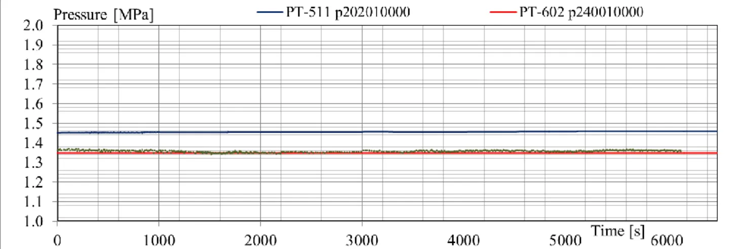
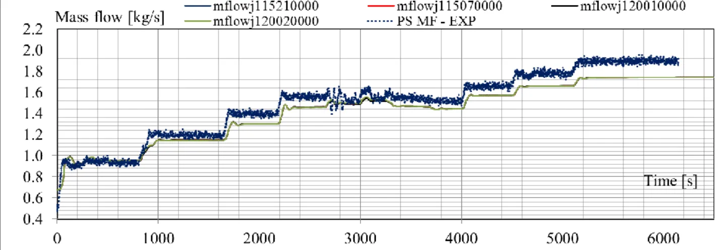
Fig. 5.8 – Test SP3, blind pretest vs. experimental results: PS pressure ... 53
Fig. 5.9 – Test SP3, blind pretest vs. experimental results: steam generator inlet (only experimental) and outlet pressures ... 53
Fig. 5.10 – Test SP3, blind pretest vs. experimental results: FW total mass flow rate, FW inner/central and outer tubes (experimental trends) mass flow rate and SG outlet (calculated value) mass flow rate... 53
Fig. 5.11 – Test SP3, blind pretest vs. experimental results: FW and steam line temperatures ... 54
Fig. 5.12 – Test SP3, blind pretest vs. experimental results: calculated steam temperature at SG outlet and SG tubes outlet fluid temperatures ... 54
Fig. 5.13 – Test SP3, blind pretest vs. experimental results: primary system coolant temperature, liquid phase (lower plenum, core outlet, SG outlet, riser, riser outlet and PRZ) ... 54
Fig. 5.14 – Test SP3, blind pretest vs. experimental results: primary system mass flow
rate (core inlet, outlet chimney outlet SG inlet) ... 55
Fig. 5.15 – Test SP3, blind pretest vs. experimental results: calculated core power - cntrlvar60 (transfer to fluid), calculated SG power cntrlvar70, experimental electrical power ... 55
Fig. 6.1 – Simulation of SBO transient: main FW flow ... 60
Fig. 6.2 – Simulation of SBO transient: steam line coolant temperature ... 60
Fig. 6.3 – Simulation of SBO transient: cladding temperature ... 60
Fig. 6.4 – Simulation of SBO transient: PS and HPC pressures ... 61
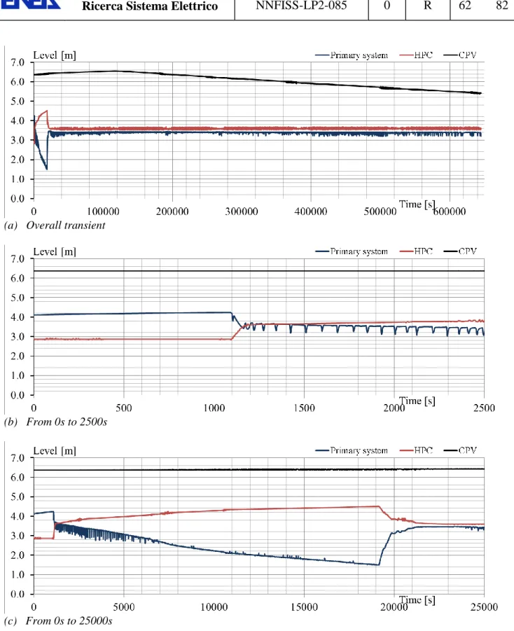
Fig. 6.5 – Simulation of SBO transient: primary system, HPC and CPV levels ... 62
Fig. 6.6 – Simulation of SBO transient: primary system coolant temperatures ... 63
Fig. 6.7 – Simulation of SBO transient: primary system mass flow rate ... 64
Fig. 6.8 – Simulation of SBO transient: mass flow rates through ADS vent valves 1 and 2 and sump valves 1 and 2 ... 65
Fig. 6.9 – Simulation of SBO transient: HPC coolant temperatures ... 66
Fig. 6.10 – Simulation of SBO transient: CPV coolant temperatures ... 67
Fig. 6.11 – Simulation of SBO transient: energy exchanged between the primary system heated rods and the coolant ... 68
Fig. 6.12 – Sensitivity analysis RUN 1 vs. RUN 2 vs. RUN3: ADS vent valve 1 mass flow rate (blue “01a”; red “01a_vlv05”, black “01a_vlv01”) ... 71
Fig. 6.13 – Sensitivity analysis RUN 1 vs. RUN 2 vs. RUN3: primary system and HPC pressures (blue “01a”; red “01a_vlv05”, black “01a_vlv01”) ... 71
Fig. 6.14 – Sensitivity analysis RUN 1 vs. RUN 2 vs. RUN3: primary system and HPC levels (blue “01a”; red “01a_vlv05”, black “01a_vlv01”) ... 71
Fig. 6.15 – Sensitivity analysis RUN 1 vs. RUN 2 vs. RUN3: cladding temperature at top of the electrical core (blue “01a”; red “01a_vlv05”, black “01a_vlv01”) ... 72
Fig. 6.16 – Sensitivity analysis RUN 1 vs. RUN 4 vs. RUN5: primary and HPC pressures (blue “01a”; red “021a”, green “022a”) ... 72
Fig. 6.17 – Sensitivity analysis RUN 1 vs. RUN 4 vs. RUN5: primary and HPC levels (blue “01a”; red “021a”, green “022a”) ... 73
Fig. 6.18 – Sensitivity analysis RUN 4 vs. RUN5: ADS vent valves, SUMP valves and HTC top valve mass flow rates ... 73
Fig. 6.19 – Sensitivity analysis RUN 1 vs. RUN 4 vs. RUN5: cladding temperature at top of the electrical core (blue “01a”; red “021a”, green “022a”) ... 74
Fig. 6.20 – Sensitivity analysis RUN 1 vs. RUN 6: primary and HPC pressures (blue “01a”; red “03a”) ... 74
Fig. 6.21 – Sensitivity analysis RUN 1 vs. RUN 6: primary and HPC levels (blue “01a”; red “03a”) ... 75
Fig. 6.22 – Sensitivity analysis RUN 1 vs. RUN 6: cladding temperature at top of the
electrical core (blue “01a”; red “03a”) ... 75 Fig. 6.23 – Sensitivity analysis RUN 7 (ID “082a”): ADS VENT valves, ADS valves,
SUMP valves and HTC top valve mass flow rates ... 75 Fig. 6.24 – Sensitivity analysis RUN 1 vs. RUN 7: primary and HPC pressures (blue
“01a”; red “082a”) ... 76 Fig. 6.25 – Sensitivity analysis RUN 1 vs. RUN 7: primary and HPC levels (blue
“01a”; red “082a”) ... 76 Fig. 6.26 – Sensitivity analysis RUN 1 vs. RUN 7: cladding temperature at top of the
L
IST OF TABLESTab. 2.1 – Sample list of SMR designs ... 15
Tab. 2.2 – Steady state design operating conditions ... 19
Tab. 4.1 – OSU-MASLWR test facility nodalization: main hydraulic geometrical features ... 30
Tab. 4.2 – OSU-MASLWR test facility nodalization: adopted code resources ... 39
Tab. 4.3 – OSU-MASLWR test facility configuration ... 39
Tab. 5.1 – OSU-MASLWR Test SP-2: steady-state results ... 44
Tab. 5.2 –OSU-MASLWR Test SP-2: resulting sequence of main events ... 45
Tab. 5.3 – OSU-MASLWR Test SP-3: steady-state results ... 52
Tab. 6.1 – Simulation of SBO transient: steady-state results... 59
Tab. 6.2 – Simulation of SBO transient: imposed and resulting sequence of main events ... 59
1 I
NTRODUCTORY REMARKS 1.1 FrameworkThe activity is carried out in the framework of the ―Linea Progettuale‖ 2 (LP2) of the ―Piano
Annuale di Realizzazione dell’Accordo di Programma‖ (AdP) between ENEA and MSE. The
task deals with the evaluation of the safety by design features of small modular reactor design, characterized by integral primary system layout.
Generally, small modular reactor designs are featured with high level of passive safety systems or they are inherently safe. Moreover they are characterized by a tight coupling of primary system and containment in case of the occurrence of postulated accident. In particular , the enhanced safety features of the SMR are connected with the reduced source term; the lower decay heat generated in the reactor core; the more efficient passive decay heat removal from reactor vessel and, finally, the elimination of some postulated accident. Therefore, thanks the safety features and their attractiveness for small and medium electric grids, the interest in developing these reactor design is increasing.
In this connection, ENEA is also participating in the Coordinated Research Program (CRP) on Natural Circulation Phenomena, Modeling, and Reliability of Passive Systems that Utilize Natural Circulation. This activity is a collaborative project with 18 participating organizations, based on OSU-MASLWR experimental facility experiments, which will be completed at the beginning of the 2013.
1.2 Objectives
The aim of the activity is related to the simulation of a small modular reactor design, cooled and moderated with light water and having an integral primary system layout. Two main general objectives have been pursued: 1) the qualification of a RELAP5/Mod3.3 nodalization used for the numerical simulation of the system and 2) deterministic investigations related to the capability of this small modular reactor design to cope a station blackout postulated accident scenario.
In view of these, the following specific objectives are identified and connected with the overall activity:
1. to improve the understanding of thermal-hydraulic phenomena expected to occur in normal operation and transients of SMR design;
2. to develop a numerical model by RELAP5/Mod3.3suitable for simulating a SMR design;
3. to evaluate the capability of computer codes (i.e. RELAP5/Mod3.3) to adequately predict the occurrence of important phenomena, and the corresponding behavior of nuclear systems during operating, upset and accident conditions, which are represented in experiments;
4. to identify and to select, through the code assessment (post tests) activities, those phenomena and models of interest which requires an up-date or an improvement of the capabilities of RELAP5 code;
5. to participate in the Coordinated Research Program (CRP) on Natural Circulation Phenomena, Modeling, and Reliability of Passive Systems that Utilize Natural Circulation
6. to perform preliminary detterministic investigations of a station blackout scenario to demostrate the features and the safety margins of this SMR design.
1.3 Structure of the report
The present report is divided into seven sections.
Besides the present section (one) and the conclusions (section seven), the second section is focused on a the description of the MASLWR reactor design. The reactor layout is described togheter with the main operating conditions and the engineering safety features.
The third section describes the experimental facility OSU-MASLWR, which is scaled down model of the MASLWR design. The features of the experimental facility are outline in order to better understand its RELAP5/Mod3.3 model, reported in section four. The main features, code options and user choices are provided in the nodalization description, together with the nodalization scheme.
The main results of two blind simulations (natural circulation and loss of feed water tests) are reported in chapter fifth. The code calculations were performed on the basis of the experimental specifications, therefore without the availability of the experimental data. The analysis, based on the comparisons with the experimental data distributed by OSU, demonstrates that the code is able to predict the main thermal-hydraulic phenomena and provides reliable prediction of the main parameter trends.
Finally the OSU-MASLWR nodalization has been employed to carry out deterministic investigations of station blackout scenarios. The preliminary results highlight the capability of this design to cope with a station blackout without any external intervention for at least 72 hours, thanks to the low power density and the large water inventory.
2 D
ESCRIPTION OFMASLWR
2.1 Introductory remarks on SMRNowadays, there is revival of interest in small and simpler units for generating electricity from nuclear power and for process heat. This interest in small nuclear power reactors is driven both by a desire to reduce capital costs and to provide power for small and medium electric grid systems. The technologies involved are very diverse (see Tab. 2.1) and Ref. [1]. The International Atomic Energy Agency (IAEA) defines ‗small‘ reactors, those having a electrical output under 300 MWe and ‗medium‘ up to 700 MWe.
Tab. 2.1 – Sample list of SMR designs
Name Capacity Type Developer
KLT-40S 35 MWe PWR OKBM, Russia
VK-300 300 MWe PWR Atomenergoproekt, Russia
CAREM 27 MWe PWR CNEA & INVAP, Argentina
IRIS 100-335 MWe PWR Westinghouse
mPower 125 MWe PWR Babcock & Wilcox, USA
SMART 100 MWe PWR KAERI, South Korea
NuScale 45 MWe PWR NuScale Power, USA
HTR-PM 2×10⁵ MWe HTR INET & Huaneng, China
PBMR 80 MWe HTR Eskom, South Africa
GT-MHR 285 MWe HTR General Atomics, USA –
Rosatom, Russia
BREST 300 MWe LMR RDIPE, Russia
SVBR-100 100 MWe LMR Rosatom/En+, Russia
FUJI 100 MWe MSR ITHMSO, Japan-Russia-USA
If compared with the current NPP in operation, the general features of the SMR would be: greater simplicity of design; enhanced robustness (safety margins); economy of mass production; reduced siting costs; high level of passive or inherent safety in the event of malfunction. In general, the designs belong to the Gen. III+ and Gen. IV types.
The main reasons for developing and constructing a SMR are connected with the smaller capital cost needed. These may be built independently or as modules in a larger complex, with capacity added incrementally as required (see section below on Modular construction using small reactor units). Economies of scale are provided by the numbers produced. These have the possibility to be better integrated in small electricity grids (< 4 Gwe), typical of new developing countries or for remote sites.
Generally, modern small reactors for power generation are expected to have greater simplicity of design, economy of mass production, and reduced siting costs. Most are also designed for a high level of passive or inherent safety in the event of malfunction.
In particular, the enhanced safety features of the SMR are connected with the reduced source term; the lower decay heat generated in the reactor core; the more efficient passive decay heat removal from reactor vessel and, finally, the elimination of some postulated accident.
2.2 Main features of the MASLWR design
The Multi-Application Small Light Water Reactor (MASLWR) [2] concept is a small, safe and economic natural circulation pressurized light water reactor, which has been developed by the Idaho National Laboratory (INL), Nexant Inc. and the Oregon State University (OSU). Besides, the electric power, it can be used for process heat applications such as water desalination or district heating, with deployment in a variety of locations.
The reactor concept is flexible enough for early deployment using LWR oxide fuels, in a later phase using Uranium-Thorium fuels and eventually new advanced fuels, such as metal fuels, that promise additional safety features, increased e efficiency, and more economic fuel cycle. This approach to gradual development of a nuclear power system, not practical for large high power systems, is possible only for small size modular reactors such as the MASLWR, because of simplicity of the reactor design, low cost of the module, and simplified licensing procedures based on prototype testing [2].
The power of MASLWR[3] is 150 MWth. It is designed to rely exclusively on the natural circulation and, thus has no pump on its primary side. The reactor vessel houses the core and support structures, core barrel, upper internals, shielding, control rod guides and the control and safety instrumentation, steam generator, pressurizer, heaters. Such an arrangement eliminates separate loops with steam generators, pressurizer, connecting pipes and supports. The unit consists of three basic modules[4]: the reactor module, which includes the primary vessel with the reactor and the steam generator, and the containment vessel, the turbine generator module and the main condenser module. The entire reactor module is 4.3 m (14 ft) diameter, 18.3 m (60 ft) long. This is within the state of the art fabrication capabilities[4]. It allows it to be entirely shop fabricated and transported to site on most railways or roads. Its primary flow is quite simple[5], as reported in Fig. 2.1. The long vertical tube in the center of the vertical vessel is called the riser and functions like a chimney to enhance the driving (gravity) head of the natural circulation flow. Starting from the bottom of the riser, fluid enters the core which is located in a shroud connected to the riser entrance. Flowing through the core. Here, the fluid is heated and thus ascend through the riser due to its buoyancy. Once the top of the riser is reached, the fluid is turned below the pressurizer plate and begins to descend through the outer annulus formed by the outer wall of the riser and the inner wall of the reactor vessel. Heat is removed from the primary to the secondary fluid by means of a helical coil tubes steam generator, wrapped around the riser. Thus, steam generation occurs within the reactor vessel itself with the primary fluid constituting the shell side and the secondary fluid constituting the tube side of the steam generation process. The primary fluid is cooled by contact with the coils and thus becomes negatively buoyant. As result, it descends through the outer annulus to the bottom of the vessel where it is turned upward into the riser, thereby completing its loop.
The steady state operating conditions are reported in Tab. 2.2. The design provides primary coolant temperature alsways below the saturated conditions. In addition, MASLWR is designed to provide superheated steam at the helical coil outlet to eliminate the need for separators and driers. The secondary side pressure was selected so that off-shelf low pressure steam turbine could be implemented.
Because MASLWR system has an integrated layout[4], some typycal PWR postulated accident are not plausible. The elimination of the large LOCAs, since no large primary penetrations of the reactor vessel or large loop piping exist, is only the most easily visible of the safety potential characteristics of integral reactors. Many others are possible, but they must be carefully exploited through an appropriate design that is kept focused on selecting design characteristics that are most amenable to eliminate accident initiating events.
MASLWR system relies on the following Engineered Safety Features:
High Pressure Containment Vessel;
Passive Safety Systems;
Decay Heat Removal System (DHRS);
Containment Heat Removal System (CHRS);
Severe Accident Mitigation and Prevention Design Features.
The containment (Fig. 2.3a) is designed in order to have an equilibrium pressure between reactor and containment following any LOCA always below maximum pressure. The Passive Safety Systems consist of the following componenets:
Two independent, small diameter, Steam Vent Valves;
Two independent, small diameter steam, Automatic Depressurization System valves;
Two independent, small diameter steam, Sump Recirculation Valves
The Decay Heat Removal System (DHRS) consist of the following features (Fig. 2.3b): Two independent trains of emergency FW.
Water is drawn from the containment cooling pool through a sump screen.
Steam is vented through spargers and condensed in the containment pool.
FW accumulators provide initial feed flow while DHRS transitions to natural circulation flow.
Pool provides a 3 day cooling supply for decay heat removal
The Decay Heat Removal Using Containment (CHRS) has the following functions (Fig. 2.3c):
provides a means of removing core decay heat and limits containment pressure by: steam condensation, convective heat transfer, heat conduction and sump recirculation;
vents the RPV steam through the reactor vent valves (flow limiter);
condenses the steam in containment;
collects the condensate in lower containment region (sump);
Fig. 2.1 – MASLWR layout
(a) Schematic of the MASLWR exterior cooling pool and turbine generator set
(b) Sample of multiple installation
(a) High Pressure Containment Vessel and Reactor Pressure Vessel
(b) Decay Heat Removal SGs (DHRS)
(c) Decay Heat Removal Using Containment (CHRS)
Fig. 2.3 – Overview of the MASLWR Engineered Safety Features
Tab. 2.2 – Steady state design operating conditions
System Parameter Unit Value
Pri m ary sys tem Reactor power MWth 150
Primary pressure MPa 7.60
Primary mass flow rate kg/s 597
Reactor inlet temperature K 491
Reactor outlet temperature K 544
Saturation temperature K 565
Reactor outlet void fraction -- 0.0
Secondary sys
tem
Steam pressure MPa 1.50
Steam outlet quality -- 1.0
Steam temperature K 481
Stauration temperature K 471
Feedwater temperature K 310
3 OSU-MASLWR
INTEGRAL TEST FACILITYOSU-MASLWR integral test facility [6] is designed on the basis of the results of the scaling analysis in order to properly model steady state and transient behavior of the prototype reactor. The following specific objectives have been met for each mode of operation:
the similarity groups which should be preserved between the test facility and the full scale prototype were obtained;
the priorities for preserving the similarity groups were established;
the important processes were identified and addressed;
the specifications for the facility design were provided; and
the biases due to scaling distortions were identified.
OSU-MASLWR test facility (Fig. 3.1) models the MASLWR conceptual design including reactor pressure vessel cavity and containment structure[5]. It is scaled at 1:3 length scale, 1:254 volume scale and 1:1 time scale. It is constructed entirely of stainless steel, and is designed for full pressure (11.4 MPa) and full temperature (590 K) prototype operation of the original design in Ref. [3].
The test facility includes three major component packages[6]. The first is the primary circuit, which includes the reactor pressure vessel with its internal components (core, hot leg riser, steam generator, pressurizer) and ADS blowdown lines, vent lines and sump recirculation lines. Then, there is the secondary circuit, which includes the steam generator (internal to vessel), feed water pumps, and associated feed water and steam valves. The third is the
containment structure. OSU-MASLWR test facility models the containment structure, in
which the reactor pressure vessel sits, and the cavity within which the containment structure is located.
In addition to the physical structures that comprise the test facility, there is an instrumentation and control systems. The data generated by the testing program is being used to validate computer code calculations and to provide a better understanding of the core natural circulation thermal-hydraulic phenomena. Indeed, it has being used to aid in the design of the MASLWR and it is involved in a IAEA ICSP on MASLWR – Experiments and TH Code Benchmarks.
The primary circuit[6] of the test facility models the self-contained integrated reactor core and steam generator system. The core is simulated with electric heaters. The steam generator is comprised of helical coils that are located in the primary pressure vessel, above the core and outside of the hot leg chimney. The relative thermal barycentre hights of core and steam generator is designed to provide a sufficient natural circulation flow under normal steady state and transient operating conditions.
The primary circuit of the test facility has been designed with limits for operation at a primary side pressure of 11.4 MPa and a primary side temperature of 590 K. Primary coolant flow is
upwards through the core and hot leg riser. This hot fluid is cooled by the steam generator in the upper portion of the vessel. The cooler fluid flows downward around the outside of the hot leg riser into the lower plenum. From the lower plenum the fluid is drawn back into the core and heated once more. Fig. 3.2 shows the scheme of the test facility primary circuit components. The test facility core consists of 56 electric heaters distributed in a square array with a maximum core power of 700 kW (reduced to 398 kW after the installation of the new fuel core bundle) [7]. The core geometry and thermal characteristics (flow areas, hydraulic diameters and local heat flux) have been preserved on a scaled basis.
The steam generator[6] (SG) is a helical coil, once through heat exchanger located within the pressure vessel in the annular space between the hot leg riser and the inside surface of the pressure vessel shell. Feed water is pumped into the SG tubes from a feedwater storage tank. This pump uses a variable speed controller to allow for precise control of the feed water mass flow rate. The steam produced is vented to atmosphere. The SG consists of three separate parallel helical coil tube sections. The outer and middle coils consist of five tubes each while the inner coil consists of four tubes. Each coil is separate from the others but the tubes within a coil are joined at a common inlet header to ensure pressure equilibrium. Cold feedwater enters at the bottom of the SG and boils off after traveling a certain length in the SG tubes. This boil off length is a function of both core power and feed water flow rate. Nominally, this boil off length is approximately 40% shorter than the actual length of the steam generator tubes so the steam will leave the SG superheated. Each SG coil exhausts the superheated steam into a common steam drum from where it is subsequently exhausted to atmosphere. The MASLWR containment vessel[6] and the surrounding containment pool are modeled in the OSU MASLWR test facility as two separate vessels. One vessel models the suppression pool volume, vapor bubble volume and the condensation surface inside of the containment vessel. The second vessel models the heat capacity of the water pool within which the containment vessel is held. The two vessels are separated by a stainless steel plate. This plate models the scaled heat transfer surface between the containment vessel and the surrounding vessel pool. Fig. 3.1 and Fig. 3.3 show these two vessels. The containment vessel is connected to the reactor pressure vessel (RPV) by six independent automatic depressurization system (ADS) lines. There are two blowdown lines, two vent lines and two sump recirculation (core makeup) lines. Flow through each of these lines is via an independent automatically operated valve controlled through the test facility control system. The containment vessel is capable of prolonged operation at 2.07 MPa and 477.6 K.
The test facility is instrumented[6] to capture the behavior of the facility during steady-state and transient operation. The following information can be obtained by the test facility data acquisition system:
Feed water—mass flow rate and temperature,
Feed water through each SG coil—mass flow rate, temperature and pressure,
Main steam—volumetric flow rate and pressure,
Differential pressure—across core, hot leg chimney, SG, and annulus below SG,
Pressurizer—coolant level, pressure and temperature, and
Temperatures—core inlet, core exit, primary loop at SG.
The test facility control system accomplishes two tasks. The first is to process input signals from the various facility instrumentation (thermocouples, pressure meters, flow meters, valve
and relay positions). The second is to generate control signals determined by the system logic (valve and relay control signals, heater and pump control signals). The following systems can be regulated by the test facility control system:
• Core heaters (including decay power modeling), • Main feed water pump,
• Pressurizer heaters,
• Feedwater storage tank level,
• Pressurizer water level (draining during system heatup only), and
• Containment heaters (used to maintain an adiabatic boundary condition on all walls of containment except for the prescribed condensation wall ensuring that heat transfer only takes place between the containment pool vessel and the high pressure containment vessel).
Fig. 3.1 – Photo of OSU MASLWR Test Facility
(a) Photo (b) Schematization (c) Deatils
4 RELAP5
NODALIZATION OFOSU-MASLWR
ITF
4.1 RELAP5/Mod3.3 codeRELAP5 code is a widely diffused code and constitutes the object of continuous assessment in various international institutions. Wide qualification projects and sensitivity and uncertainty analyses of physical models have been performed all over the world, Refs. [8], [9] and [10]. The RELAP5 is well known and a wide literature exists about the code description, capability and application.
The light water reactor transient analysis code, RELAP5, was developed at Idaho National Engineering Laboratory (INEL) for the U.S. Nuclear Regulatory Commission (NRC). The RELAP5 code has been developed for the best estimate simulation of LWR coolant system transients during normal and off normal conditions. The code models the coupled behavior of the reactor coolant system and the core (point kinetic) for simulating accidents in LWR: such as loss of coolant, Anticipated Transients Without Scram (ATWS) and operational transients, such as loss of feed-water, loss of offsite power and turbine trip. A generic modeling approach is used that permits simulating a variety of thermal hydraulic systems such as turbines, condensers and secondary feed-water systems. The component models include also pumps, valves, pipes, heat releasing or absorbing structures, reactor point kinetics, electric heaters, jet pumps, etc.
This code is highly generic and can be used for simulation of a wide variety of hydraulic and thermal transients in both nuclear and non-nuclear systems involving mixtures of steam, water, non-condensable and solute. The developers of the RELAP5/Mod3 wanted to create a code version suitable for the analysis of all transient and postulated accidents in LWR systems, including small and large break Loss Of Coolant Accidents (LOCA).
Based on one-dimensional, transient, and non-homogeneous and non-equilibrium hydrodynamic model for the steam and liquid phases, RELAP5/Mod3 code uses a set of six partial derivative balance equations and can treat a non-condensable component in the steam phase and a non-volatile component (boron) in the liquid phase.
A semi-implicit numeric scheme is used to solve the equations inside control volumes connected by junctions. The fluid scalar properties (pressure, energy, density and void fraction) are the average fluid condition in the volume and are viewed located at the control volume center. The fluid vector properties, i.e. velocities, are located at the junctions and are associated with mass and energy flows between control volumes that are connected in series, using junctions to represents flow paths. The direction associated to the control volume is positive from the inlet to the outlet.
Heat flow paths are also modeled in a one-dimensional sense, using a staggered mesh to calculate temperatures and heat flux vectors. Heat structures and hydrodynamic control volumes are connected through heat flux, calculated using a boiling heat transfer formulation.
These structures are used to simulate pipe walls, heater elements, nuclear fuel pins and heat exchanger surfaces.
4.2 Computer hardware and software tools
All calculations described hereafter have been carried out using the following tools:
Workstation HP
o Operative system WINDOWS 7 Professional (64bit) o Intel® XEON @ 3.2GHz
o RAM 16 GB
Software
o EC Wingraf and MS EXCEL 2010 for the post processing phase
4.3 OSU-MASLWR nodalization description
The nodalization derives from the preliminary 3D model set up for RELAP5-3D© representing OSU-MASLWR facility (Ref. [11]) by means of merging the azimuthal subdivisions of the models. It has been tested against two experimental tests consisting in a natural circulation test and a loss of normal feedwater [12], [13]. The code results were calculated as blind exercise, as discussed in section 5.
Modeling
The OSU-MASLWR facility is represented by the RELAP5 nodalization, as following:
RPV
The bottom region, connecting the downcomer part and the core zone, is represented with a BRANCH component.
The core and the riser are modeled with a single pipe having 33 sub-volumes. The core region consists of 6 out of 33 sub-volumes.
The region below the top plate of the primary system, which separates the PRZ zone and the ascending and descending sides concentric regions, has been modeled with a single BRANCH.
The cold side and the downcomer regions are modeled with a single pipe having 33 sub-volumes. 8 out of 33 sub-volumes are linked to the secondary system by means of thermal structures.
The pipe on the top represents the PRZ region
Secondary system
It is represented with a single equivalent channel plus a PIPE representing the plugged tube.
The helical coil SG is represented with a single pipe having 42 sub-volumes. The heat exchange with the primary system is modeled with a thermal structure connected to 38 out of 42 sub-volumes.
The FW temperature is imposed with a TIME DEPENDENT VOLUME component.
The mass flow rate can regulated with a PI controller connected with a TMDPJUN component.
The system pressure is imposed with a TIME DEPENDENT VOLUME component at the steam line outlet.
The CPV and the HPC are modeled with two parallel stack of PIPE and BRANCH components. The model approach is based on Ref. [17].
The following modeling features apply[12]:
the elevations of the different parts of the facility are maintained in the nodalization;
the SG secondary side tubes are modeled using the ―average‖ inclination angle of the real geometry, thus horizontal flow regime is applied in the equivalent tube;
the node to node ratio is kept uniform with a maximum ratio of 1.2 between adjacent sub-volumes;
the sliced approach is applied at all systems (i.e. primary, secondary, HPC, CPV and interfacing systems).
the chocked flow is calculated using the Henry Fauske model.
Nodalization diagram
The nodalization used for all analyses described in the present report is depicted in Fig. 4.1.
Geometric data used in code and the list of parameters
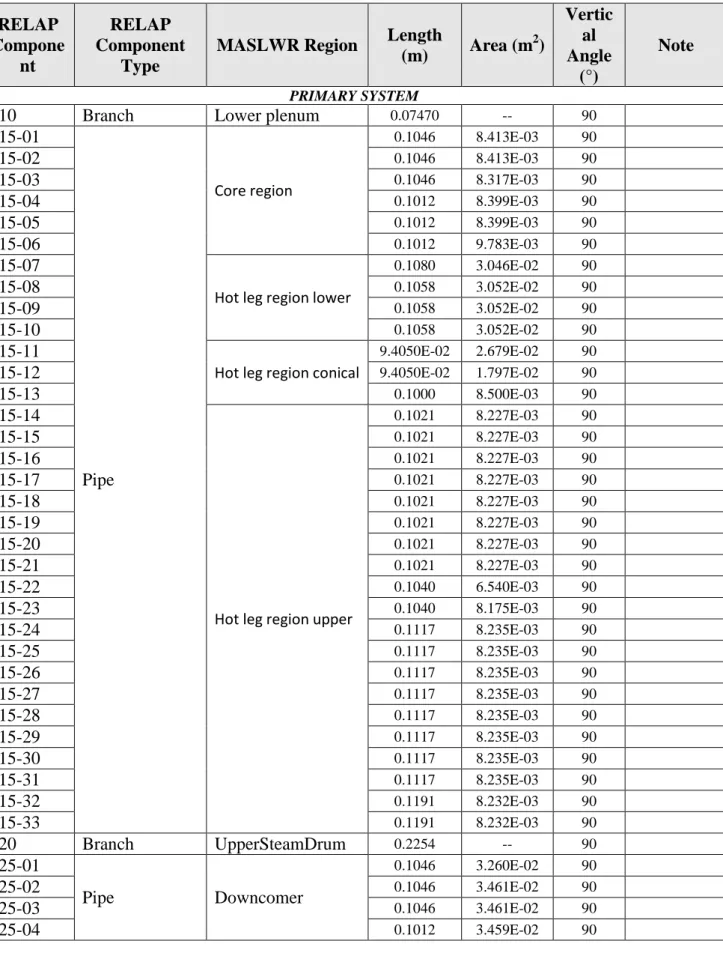
The main hydraulic geometrical features and the adopted code resources are reported respectively in Tab. 4.1 and Tab. 4.2 reports the number of each RELAP5 component, the corresponding zone in OSU-MASLWR facility, the component type, the geometrical description (area and length), and the inclination. The energy loss coefficients used in the junctions are evaluated or estimated on the basis of the geometry. The roughness is set 5.0E-5 m with the exception of the core region and the SG tubes (5.0E-6 m).
Heat structure data
The main heat structures modeling features are reported in Ref. [12], where the different part of the OSU-MASLWR are connected with the nodalization components and described in terms of options and geometrical characteristics. The material proprieties are taken by the IAEA ICSP documentation [13], when available.
Control logic
Tab. 4.1 – OSU-MASLWR test facility nodalization: main hydraulic geometrical features RELAP Compone nt RELAP Component Type
MASLWR Region Length
(m) Area (m 2 ) Vertic al Angle (°) Note PRIMARY SYSTEM
110 Branch Lower plenum 0.07470 -- 90
115-01 Pipe Core region 0.1046 8.413E-03 90 115-02 0.1046 8.413E-03 90 115-03 0.1046 8.317E-03 90 115-04 0.1012 8.399E-03 90 115-05 0.1012 8.399E-03 90 115-06 0.1012 9.783E-03 90 115-07
Hot leg region lower
0.1080 3.046E-02 90
115-08 0.1058 3.052E-02 90
115-09 0.1058 3.052E-02 90
115-10 0.1058 3.052E-02 90
115-11
Hot leg region conical
9.4050E-02 2.679E-02 90
115-12 9.4050E-02 1.797E-02 90
115-13 0.1000 8.500E-03 90
115-14
Hot leg region upper
0.1021 8.227E-03 90 115-15 0.1021 8.227E-03 90 115-16 0.1021 8.227E-03 90 115-17 0.1021 8.227E-03 90 115-18 0.1021 8.227E-03 90 115-19 0.1021 8.227E-03 90 115-20 0.1021 8.227E-03 90 115-21 0.1021 8.227E-03 90 115-22 0.1040 6.540E-03 90 115-23 0.1040 8.175E-03 90 115-24 0.1117 8.235E-03 90 115-25 0.1117 8.235E-03 90 115-26 0.1117 8.235E-03 90 115-27 0.1117 8.235E-03 90 115-28 0.1117 8.235E-03 90 115-29 0.1117 8.235E-03 90 115-30 0.1117 8.235E-03 90 115-31 0.1117 8.235E-03 90 115-32 0.1191 8.232E-03 90 115-33 0.1191 8.232E-03 90 120 Branch UpperSteamDrum 0.2254 -- 90 125-01 Pipe Downcomer 0.1046 3.260E-02 90 125-02 0.1046 3.461E-02 90 125-03 0.1046 3.461E-02 90 125-04 0.1012 3.459E-02 90
RELAP Compone nt RELAP Component Type
MASLWR Region Length
(m) Area (m 2 ) Vertic al Angle (°) Note 125-05 0.1012 3.419E-02 90 125-06 0.1012 3.241E-02 90 125-07 Cold leg 0.1080 3.454E-02 90 125-08 0.1058 3.458E-02 90 125-09 0.1058 3.458E-02 90 125-10 0.1058 3.458E-02 90 125-11 9.4050E-02 3.690E-02 90 125-12 9.4050E-02 4.157E-02 90 125-13 0.1000 5.130E-02 90 125-14 0.1021 5.671E-02 90 125-15 0.1021 5.671E-02 90 125-16 0.1021 5.671E-02 90 125-17 0.1021 5.671E-02 90 125-18 0.1021 5.671E-02 90 125-19 0.1021 5.671E-02 90 125-20 0.1021 5.671E-02 90 125-21 0.1021 5.495E-02 90 125-22 0.1040 4.847E-02 90 125-23 SG primary side outlet 0.1040 4.116E-02 90 125-24 SG primary tube region 0.1117 4.117E-02 90 125-25 0.1117 4.117E-02 90 125-26 0.1117 4.117E-02 90 125-27 0.1117 4.117E-02 90 125-28 0.1117 4.117E-02 90 125-29 0.1117 4.117E-02 90 125-30 0.1117 4.117E-02 90 125-31 0.1117 4.180E-02 90 125-32 SG primary side inlet 0.1191 5.216E-02 90 125-33 -- 0.1191 5.678E-02 90 130-01 Pipe PRZ 0.1153 6.411E-02 90 130-02 0.1153 5.075E-02 90 130-03 0.1153 6.567E-02 90 130-04 0.1153 6.567E-02 90 130-05 0.1153 6.567E-02 90 130-06 8.2000E-02 4.878E-02 90 SECONDARY SYSTEM 200 Tmdpvol FW Tank -- -- -- 201 Tmdpjun FW Pump -- -- -- 202-01 Pipe FW pipeline (fictitious) 0.2000 5.950E-02 0 202-02 0.2000 5.950E-02 0 202-03 0.2000 5.950E-02 0
RELAP Compone nt RELAP Component Type
MASLWR Region Length
(m) Area (m 2 ) Vertic al Angle (°) Note 202-04 0.2000 5.950E-02 0 202-05 0.2000 5.950E-02 0
203 Valve Inlet valve -- -- --
204 Branch SG tube distributor 0.20 0.02780 0 220-01 Pipe SG tubes (equivalent) 0.2000 1.62E-03 0 220-02 0.2000 1.62E-03 0 220-03 0.2000 1.62E-03 0 220-04 0.2000 1.62E-03 0 220-05 0.2000 1.62E-03 0 220-06 0.1922 1.62E-03 90 220-07 0.1922 1.62E-03 90 220-08 0.1922 1.62E-03 90 220-09 0.1922 1.62E-03 90 220-10 0.1922 1.62E-03 90 220-11 0.1922 1.62E-03 90 220-12 0.1922 1.62E-03 90 220-13 0.1922 1.62E-03 90 220-14 0.1922 1.62E-03 90 220-15 0.1922 1.62E-03 90 220-16 0.1922 1.62E-03 90 220-17 0.1922 1.62E-03 90 220-18 0.1922 1.62E-03 90 220-19 0.1922 1.62E-03 90 220-20 0.1922 1.62E-03 90 220-21 0.1922 1.62E-03 90 220-22 0.1922 1.62E-03 90 220-23 0.1922 1.62E-03 90 220-24 0.1922 1.62E-03 90 220-25 0.1922 1.62E-03 90 220-26 0.1922 1.62E-03 90 220-27 0.1922 1.62E-03 90 220-28 0.1922 1.62E-03 90 220-29 0.1922 1.62E-03 90 220-30 0.1922 1.62E-03 90 220-31 0.1922 1.62E-03 90 220-32 0.1922 1.62E-03 90 220-33 0.1922 1.62E-03 90 220-34 0.1922 1.62E-03 90 220-35 0.1922 1.62E-03 90 220-36 0.1922 1.62E-03 90 220-37 0.1922 1.62E-03 90 220-38 0.2000 1.62E-03 0 220-39 0.2000 1.62E-03 0
RELAP Compone nt RELAP Component Type
MASLWR Region Length
(m) Area (m 2 ) Vertic al Angle (°) Note 220-40 0.2000 1.62E-03 0 220-41 0.2000 1.62E-03 0 220-42 0.2000 1.62E-03 0 221-01
Pipe SG tubes (plugged)
0.2000 1.24E-04 0 221-02 0.2000 1.24E-04 0 221-03 0.2000 1.24E-04 0 221-04 0.2000 1.24E-04 0 221-05 0.2000 1.24E-04 0 221-06 0.1922 1.24E-04 90 221-07 0.1922 1.24E-04 90 221-08 0.1922 1.24E-04 90 221-09 0.1922 1.24E-04 90 221-10 0.1922 1.24E-04 90 221-11 0.1922 1.24E-04 90 221-12 0.1922 1.24E-04 90 221-13 0.1922 1.24E-04 90 221-14 0.1922 1.24E-04 90 221-15 0.1922 1.24E-04 90 221-16 0.1922 1.24E-04 90 221-17 0.1922 1.24E-04 90 221-18 0.1922 1.24E-04 90 221-19 0.1922 1.24E-04 90 221-20 0.1922 1.24E-04 90 221-21 0.1922 1.24E-04 90 221-22 0.1922 1.24E-04 90 221-23 0.1922 1.24E-04 90 221-24 0.1922 1.24E-04 90 221-25 0.1922 1.24E-04 90 221-26 0.1922 1.24E-04 90 221-27 0.1922 1.24E-04 90 221-28 0.1922 1.24E-04 90 221-29 0.1922 1.24E-04 90 221-30 0.1922 1.24E-04 90 221-31 0.1922 1.24E-04 90 221-32 0.1922 1.24E-04 90 221-33 0.1922 1.24E-04 90 221-34 0.1922 1.24E-04 90 221-35 0.1922 1.24E-04 90 221-36 0.1922 1.24E-04 90 221-37 0.1922 1.24E-04 90 221-38 0.2000 1.24E-04 0 221-39 0.2000 1.24E-04 0 221-40 0.2000 1.24E-04 0
RELAP Compone nt RELAP Component Type
MASLWR Region Length
(m) Area (m 2 ) Vertic al Angle (°) Note 221-41 0.2000 1.24E-04 0 221-42 0.2000 1.24E-04 0 240 Branch SG collector (fictitious) 0.20 0.16980 0
241 Valve Regulation valve -- -- --
242 Tmdpvol -- -- -- --
HIGH PRESSURE CONTAINMENT SYSTEM
400-01
Pipe Lower cylindrical vessel outer part 1
0.2000 1.6130E-02 90
400-02 0.1793 1.6130E-02 90
400-03 0.2092 1.6130E-02 90
400-04 0.2024 1.6130E-02 90
401-01
Pipe Lower cylindrical vessel inner part 1
0.2000 3.7630E-02 90 401-02 0.1793 3.7630E-02 90 401-03 0.2092 3.7630E-02 90 401-04 0.2024 3.7630E-02 90 402 Multiple Junction Connections inner-outer -- -- --
405 Branch Lower cylindrical
vessel outer part 2 0.20920 0.01613 90 406 Branch Lower cylindrical
vessel inner part 2 0.20920 0.03763 90 410-01
Pipe Lower cylindrical vessel outer part 3
0.2117 1.6130E-02 90
410-02 0.1999 1.6130E-02 90
411-01
Pipe Lower cylindrical vessel inner part 3
0.2117 3.7630E-02 90 411-02 0.1999 3.7630E-02 90 412 Multiple Junction Connections inner-outer -- -- --
415 Branch Lower cylindrical
vessel outer part 4 0.19405 0.01613 90 416 Branch Lower cylindrical
vessel inner part 4 0.19405 0.03763 90 420-01
Pipe
Lower cylindrical vessel outer and eccentric parts 0.2042 1.6130E-02 90 420-02 0.2042 1.6130E-02 90 420-03 0.2042 1.6130E-02 90 420-04 0.2042 1.6130E-02 90 420-05 0.2080 1.6130E-02 90 420-06 0.2234 1.6130E-02 90 420-07 0.2234 1.6130E-02 90 420-08 0.2234 1.6130E-02 90 420-09 0.2234 1.6130E-02 90 420-10 0.2381 1.6130E-02 90 420-11 0.3407 3.6140E-02 90 420-12 0.2306 3.6140E-02 90
RELAP Compone nt RELAP Component Type
MASLWR Region Length
(m) Area (m 2 ) Vertic al Angle (°) Note 421-01 Pipe Lower cylindrical vessel inner and eccentric parts 0.2042 3.7630E-02 90 421-02 0.2042 3.7630E-02 90 421-03 0.2042 3.7630E-02 90 421-04 0.2042 3.7630E-02 90 421-05 0.2080 3.7630E-02 90 421-06 0.2234 3.7630E-02 90 421-07 0.2234 3.7630E-02 90 421-08 0.2234 3.7630E-02 90 421-09 0.2234 3.7630E-02 90 421-10 0.2381 3.7630E-02 90 421-11 0.3407 8.4320E-02 90 421-12 0.2306 8.4320E-02 90 422 Multiple Junction Connections inner-outer -- -- --
425 Branch Upper cylindrical
vessel outer part 1 0.23056 0.05855 90 426 Branch Upper cylindrical
vessel inner part 1 0.23056 0.13661 90 430-01
Pipe Upper cylindrical vessel outer part 2
0.2099 5.8550E-02 90
430-02 0.2500 5.8550E-02 90
430-03 0.3000 5.8550E-02 90
430-04 0.2759 5.8550E-02 90
431-01
Pipe Upper cylindrical vessel inner part 2
0.2099 0.1366 90 431-02 0.2500 0.1366 90 431-03 0.3000 0.1366 90 431-04 0.2759 0.1366 90 432 Multiple Junction Connections inner-outer -- -- --
435 Branch Top cylindrical
vessel outer part 1 0.17000 0.040985 90 436 Branch Top cylindrical
vessel inner part 1 0.17000 0.095627 90 440-01
Pipe
Vent line top (estimation based on drawings) 0.2500 3.1416E-04 90 440-02 0.2500 3.1416E-04 90 440-03 0.2500 3.1416E-04 0 440-04 0.2500 3.1416E-04 -90 440-05 0.2500 3.1416E-04 -90
441 Valve Relief valve -- -- --
442 Tmdpvol -- -- --
CONTAINMENT COOLING POOL
500-01
Pipe CPV inner part
0.3000 0.3087 90
500-02 0.3000 0.3087 90
RELAP Compone nt RELAP Component Type
MASLWR Region Length
(m) Area (m 2 ) Vertic al Angle (°) Note 500-04 0.1793 0.3087 90 500-05 0.2092 0.3087 90 500-06 0.2024 0.3087 90 500-07 0.2092 0.3087 90 500-08 0.2117 0.3087 90 500-09 0.1999 0.3087 90 500-10 0.1941 0.3087 90 500-11 0.2042 0.3087 90 500-12 0.2042 0.3087 90 500-13 0.2042 0.3087 90 500-14 0.2042 0.3087 90 500-15 0.2080 0.3087 90 500-16 0.2234 0.3087 90 500-17 0.2234 0.3087 90 500-18 0.2234 0.3087 90 500-19 0.2234 0.3087 90 500-20 0.2381 0.3087 90 500-21 0.3407 0.3087 90 500-22 0.2306 0.3087 90 500-23 0.2306 0.3087 90 500-24 0.2099 0.3087 90 500-25 0.2500 0.3087 90 500-26 0.3000 0.3087 90 500-27 0.2759 0.3087 90 500-28 0.1700 0.3087 90 500-29 0.1700 0.3087 90 500-30 0.1700 0.3087 90 500-31 0.1700 0.3087 90 500-32 0.2350 0.3087 90 501-01
Pipe CPV outer part
0.3000 0.1323 90 501-02 0.3000 0.1323 90 501-03 0.2000 0.1323 90 501-04 0.1793 0.1323 90 501-05 0.2092 0.1323 90 501-06 0.2024 0.1323 90 501-07 0.2092 0.1323 90 501-08 0.2117 0.1323 90 501-09 0.1999 0.1323 90 501-10 0.1941 0.1323 90 501-11 0.2042 0.1323 90 501-12 0.2042 0.1323 90 501-13 0.2042 0.1323 90 501-14 0.2042 0.1323 90
RELAP Compone nt RELAP Component Type
MASLWR Region Length
(m) Area (m 2 ) Vertic al Angle (°) Note 501-15 0.2080 0.1323 90 501-16 0.2234 0.1323 90 501-17 0.2234 0.1323 90 501-18 0.2234 0.1323 90 501-19 0.2234 0.1323 90 501-20 0.2381 0.1323 90 501-21 0.3407 0.1323 90 501-22 0.2306 0.1323 90 501-23 0.2306 0.1323 90 501-24 0.2099 0.1323 90 501-25 0.2500 0.1323 90 501-26 0.3000 0.1323 90 501-27 0.2759 0.1323 90 501-28 0.1700 0.1323 90 501-29 0.1700 0.1323 90 501-30 0.1700 0.1323 90 501-31 0.1700 0.1323 90 501-32 0.2350 0.1323 90 502 Multiple Junction Connections inner-outer -- -- --
AUTOMATIC DEPRESSURIZATION SYSTEMS
300 Branch SUMP line 1 inlet 0.18 6.95E-05 0
301 Valve SUMP valve 1 -- 6.91 E-05 --
302-01
Pipe SUMP line 1
0.25000 0.000193 0 302-02 0.25000 0.000193 0 302-03 0.25000 0.000193 0 302-04 0.25000 0.000193 0 302-05 0.25000 0.000193 0 302-06 0.25000 0.000193 0 302-07 0.33000 0.000193 0 302-08 0.33000 0.000193 0 302-09 0.33000 0.000193 0 302-10 0.33000 0.000193 0 302-11 0.2092 0.000279 -90 302-12 0.2024 0.000279 -90
303 Sngljun SUMP line 1 outlet -- -- --
320 Branch SUMP line 2 inlet 0.18 6.95E-05 0
321 Valve SUMP valve 2 -- 6.91 E-05 --
322-01
Pipe SUMP line 2
0.25000 0.000193 0
322-02 0.25000 0.000193 0
322-03 0.25000 0.000193 0
322-04 0.25000 0.000193 0
RELAP Compone nt RELAP Component Type
MASLWR Region Length
(m) Area (m 2 ) Vertic al Angle (°) Note 322-06 0.25000 0.000193 0 322-07 0.33000 0.000193 0 322-08 0.33000 0.000193 0 322-09 0.33000 0.000193 0 322-10 0.33000 0.000193 0 322-11 0.2092 0.000279 -90 322-12 0.2024 0.000279 -90
323 Sngljun SUMP line 2 outlet -- -- --
310 Branch ADS vent line 1
inlet 0.2600 6.95E-05 0
311 Valve ADS vent valve 1 -- 3.17690E-5 --
312-01
Pipe ADS vent line 1
0.2300 0.000193 0 312-02 0.2450 0.000193 0 312-03 0.2450 0.000193 0 312-04 0.2450 0.000193 0 312-05 0.2450 0.000193 0 312-06 0.2500 0.000193 0 312-07 0.2600 0.000193 0 312-08 0.2200 0.000279 0
313 Sngljun ADS vent line 1
outlet -- -- --
330 Branch ADS vent line 2
inlet 0.2600 6.95E-05 0
331 Valve ADS vent valve 2 -- 3.17690E-5 --
332-01
Pipe ADS vent line 2
0.2300 0.000193 0 332-02 0.2450 0.000193 0 332-03 0.2450 0.000193 0 332-04 0.2450 0.000193 0 332-05 0.2450 0.000193 0 332-06 0.2500 0.000193 0 332-07 0.2600 0.000193 0 332-08 0.2200 0.000279 0
333 Sngljun ADS vent line 2
Tab. 4.2 – OSU-MASLWR test facility nodalization: adopted code resources
# QUANTITY Unit Value
1 Tot. No. of HYDR volumes -- 319
2 Tot. No. of HYDR junctions -- 378
3 Tot. No. of HYDR sub-volumes in the core -- 6
4 Tot. No. of heat structures -- 314
5 Tot. No. of mesh points in the heat structures -- 3310 6 Tot. No.of core active structures (radial x axial
meshes) 17 x 6
Tab. 4.3 – OSU-MASLWR test facility configuration
# SYSTEM CHARACTERISTICS STATUS (1) REMARKS
1 ADS vent valve 1 Orifice flow area 3.177e-5m2 Active Chocked flow model
Henry Fauske
2 ADS vent valve 2 Orifice flow area 3.177e-5m2 Active --
3 ADS valve 1 Orifice flow area 6.95E-5m2 Not
operated --
4 ADS valve 2 Orifice flow area 6.95E-5m2 Not
operated --
5 SUMP valve 1 Orifice flow area 6.90E-5m2 Active --
6 SUMP valve 2 Orifice flow area 6.90E-5m2 Active --
7 PRZ heaters
Power: 0 – 12kW
Regulated with PI control based on primary pressure signal
Active Dummy geometry
8 Core power Power imposed in general table data Active --
9 HPC relief valve
Orifice flow area 0.0003m2
HPC pressure >1.99MPa: valve opened HPC pressure <1.82MPa: valve closed
Active
Dummy flow area Operated to avoid HPC overpressure
10 HPC heaters -- Not
operated --
11 CPV relief valve Orifice flow area 0.0003m2 Not
operated
Dummy flow area Always open
12 FW Imposed mass flow rate according with
the specifications Active
13 FW valve -- Not operated The FW is imposed using a time dependent junction Always open 14 SL valve -- Not
operated Always open
Fig. 4.1 – ENEA nodalization: overall sketch
MASLWR nodalization - 1D version - Rev. 1 IAEA ICSP NC and LOFW tests - Dec. 2010
CPV System 500-32 501-32 500-32 501-32 HPC System 500-31 501-31 500-31 501-31 440-03 440-03 440-02 500-30 501-30 430-04 440-02 500-30 501-30 430-05 440-01 500-29 501-29 441vlv 440-01 500-29 501-29 442 435 436 500-28 501-28 435 436 500-28 501-28 430-04 431-04 500-27 501-27 430-04 431-04 500-27 501-27 430-03 431-03 500-26 501-26 430-03 431-03 500-26 501-26 Primary System 430-02 431-02 500-25 501-25 430-02 431-02 500-25 501-25
ADS Vent System (x2) 430-01 431-01 500-24 501-24
130-06 430-01 431-01 500-24 501-24 130-05 310 311-vlv 312-01 312-08 425 426 500-23 501-23 130-04 425 426 500-23 501-23 130-03 420-12 421-12 500-22 501-22 130-02 420-12 421-12 500-22 501-22 130-01 420-11 421-11 500-21 501-21 120 420-11 421-11 500-21 501-21 125-33 125-33 420-10 421-10 500-20 501-20 115-32 125-32 420-10 421-10 500-20 501-20 115-31 125-31 220-34/37 220-38/42 240 241vlv 242 420-09 421-09 500-19 501-19 115-30 125-30 220-30/33 420-09 421-09 500-19 501-19 115-29 125-29 220-26/29 420-08 421-08 500-18 501-18 115-28 125-28 220-221/25 Secondary System 420-08 421-08 500-18 501-18 115-27 125-27 220-18/21 420-07 421-07 500-17 501-17 115-26 125-26 220-14/17 420-07 421-07 500-17 501-17 115-25 125-25 220-10/13 201 420-06 421-06 500-16 501-16 115-24 125-24 220-06/09 220-01/05 204 203vlv 202-01/05 200 420-06 421-06 500-16 501-16 115-23 125-23 420-05 421-05 500-15 501-15 115-22 125-22 420-05 421-05 500-15 501-15 115-21 125-21 420-04 421-04 500-14 501-14 115-20 125-20 420-04 421-04 500-14 501-14 115-19 125-19 420-03 421-03 500-13 501-13 115-18 125-18 420-03 421-03 500-13 501-13 115-17 125-17 420-02 421-02 500-12 501-12 115-16 125-16 420-02 421-02 500-12 501-12 115-15 125-15 420-01 421-01 500-11 501-11 115-14 125-14 ADS System (x2) 420-01 421-01 500-11 501-11 115-13 125-13 415 416 500-10 501-10 115-12 125-12 305 306-vlv 307-01 307-10 307-11 0.00000 415 416 500-10 501-10 115-11 125-11 307-11 410-02 411-02 500-09 501-09 115-10 125-10 307-11 410-02 411-02 500-09 501-09 115-09 125-09 Sump System (x2) 307-12 410-01 411-01 500-08 501-08 115-08 125-08 307-12 410-01 411-01 500-08 501-08 115-07 125-07 300 301-vlv 302-01 302-02 302-10 302-11 405 406 500-07 501-07 115-06 125-06 302-11 405 406 500-07 501-07 115-05 125-05 302-12 400-04 401-04 500-06 501-06 115-04 125-04 302-12 400-04 401-04 500-06 501-06 115-03 125-03 400-03 401-03 500-05 501-05 115-02 125-02 400-03 401-03 500-05 501-05 115-01 125-01 400-02 401-02 500-04 501-04 110 15-vlv 900 400-02 401-02 500-04 501-04 400-01 401-01 500-03 501-03 500-03 501-03 500-02 501-02 500-02 501-02 500-01 501-01 500-01 501-01
5 Q
UALIFICATION OF THE NODALIZATIONThe nodalization has been qualified by means of the blind simulations of two experiments: 1) a loss of FW flow postulated accident and, 2) a natural circulation test. The results of the simulations are briefly outlined hereafter. The complete set of imposed sequence of main events, boundary and initial conditions and results have been issued in the framework of the IAEA ICSP, see Refs. [12] and [14].
5.1 SP-2: Loss of Feedwater Transient with Subsequent ADS Operation and Long Term Cooling
5.1.1 Steady state results
The experimental and calculated initial conditions of the test SP-2 are reported in Tab. 5.1. The initial conditions of the simulation are achieved running the code for 5000s with the ‗TRANSNT‘ (transient) option. The last 100s (from -100s up to 0s) have been considered to verify the stability of the parameter trends.
The lower parts of the HPC and of the CPV are initialized with liquid water at 0.101 MPa and 298 K. Therefore, the pressure in the bottom of these tanks is the atmospheric pressure plus the static head of the column of water. The upper volumes, above the liquid level free surface (Tab. 5.1), are initialized with nitrogen. The HPC is kept closed. Nevertheless a trip, which activates the SV-800 valve, is implemented on high pressure signal in HPC. The CPV system is kept open during the overall transient: the top of the tank is connected with the environment.
Steady state and initial conditions are achieved accordingly with the specifications. Few minor deviations are observed with the experimental results. The main difference is the core inlet temperature, which results underestimated (i.e. 5 K with respect to the specifications). It is observed a drift of the primary pressure of about 0.0015bar/s, during the last 100s. The temperatures of the coolant in primary system are stable.
5.1.2 Blind pretest results and preliminary analysis
The resulting sequence of main events is reported in Tab. 5.2. The times of the ADS valve 1 openings and closures are compared in Ref. [12]. Four phases and related phenomena are identified in the transient as hereafter reported (Tab. 5.2). The timing reported in parenthesis are referred to the code results.
1. Phase 1 – increase of energy in primary system (0-54s): from loss of FW up to the ADS vent valve 1 opening;
2. Phase 2 – primary system depressurization (54-168s): from the ADS vent valve 1 opening up to the high pressure signal in HPC;
3. Phase 3 – ADS vent valve 1 cycling (168-3882s): from the first high pressure signal in HPC up to the low pressure difference between primary system and HPC;