This content has been downloaded from IOPscience. Please scroll down to see the full text.
Download details:
IP Address: 192.167.23.210
This content was downloaded on 24/10/2016 at 14:17
Please note that terms and conditions apply.
You may also be interested in:
Performance study of the CMS barrel resistive plate chambers with cosmic rays CMS Collaboration
Fine synchronization of the CMS muon drift-tube local trigger using cosmic rays CMS Collaboration
Performance of the CMS drift-tube chamber local trigger with cosmic rays CMS Collaboration
Performance of the CMS hadron calorimeter with cosmic ray muons and LHC beam data CMS Collaboration
Measurement of the muon stopping power in lead tungstate CMS Collaboration
Performance of CMS hadron calorimeter timing and synchronization using test beam, cosmic ray, and LHC beam data
Aligning the CMS muon chambers with the muon alignment system during an extended
cosmic ray run
View the table of contents for this issue, or go to the journal homepage for more 2010 JINST 5 T03019
(http://iopscience.iop.org/1748-0221/5/03/T03019)
2010 JINST 5 T03019
PUBLISHED BYIOP PUBLISHING FORSISSA
RECEIVED: November 26, 2009 ACCEPTED: January 21, 2010 PUBLISHED: March 19, 2010 COMMISSIONING OF THECMS EXPERIMENT WITHCOSMIC RAYS
Aligning the CMS muon chambers with the muon
alignment system during an extended cosmic ray run
CMS Collaboration
ABSTRACT: The alignment system for the muon spectrometer of the CMS detector comprises three
independent subsystems of optical and analog position sensors. It aligns muon chambers with re-spect to each other and to the central silicon tracker. System commissioning at full magnetic field began in 2008 during an extended cosmic ray run. The system succeeded in tracking muon detector movements of up to 18 mm and rotations of several milliradians under magnetic forces. Depending on coordinate and subsystem, the system achieved chamber alignment precisions of 140–350 µm and 30–200 µrad, close to the precision requirements of the experiment. Systematic errors on absolute positions are estimated to be 340–590 µm based on comparisons with independent pho-togrammetry measurements.
KEYWORDS: Muon spectrometers; Large detector systems for particle and astroparticle physics
ARXIV EPRINT:0911.4770
c
2010 JINST 5 T03019
Contents1 Introduction 1
2 System layout and geometry reconstruction 3
2.1 Offline geometry reconstruction 5
2.2 Performance and validation 6
3 Data acquisition 6
4 Muon barrel alignment 7
5 Muon endcap alignment 8
5.1 Reconstruction of CSC positions 11
5.1.1 Chamber positions in stations ME2,3,4 measured with straight-line monitors 11
5.1.2 Chamber positions in ME1 13
5.2 Endcap alignment constants 15
6 Summary 15
The CMS collaboration 19
1 Introduction
The primary goal of the Compact Muon Solenoid (CMS) experiment [1] is to explore particle physics at the TeV energy scale exploiting the proton-proton collisions delivered by the Large Hadron Collider (LHC) [2]. Precise measurement of muons up to the TeV momentum range re-quires the muon chambers to be aligned with respect to each other, and to the central tracking system, with an accuracy of a few hundred microns in position and about 40 microradians in orien-tation. The CMS Collaboration conducted a month-long data-taking exercise known as the Cosmic Run At Four Tesla (CRAFT) during October and November of 2008, with the goal of commission-ing the experiment for extended operation [3]. With all installed detector systems participating, CMS recorded 270 million cosmic-ray muon triggered events with the solenoid at its nominal axial field strength of 3.8 T. This paper focuses on the muon alignment system and the results obtained with the data taken during the CRAFT exercise. A separate paper describes in detail the track-based muon alignment procedures and results [4]. A complete alignment of all muon chambers was not available for CRAFT; the partial results shown here reflect the level of development of the system by the end of November 2008.
The central feature of the CMS apparatus is a superconducting solenoid of 6 m internal diam-eter, 13 m length, and 4 T magnetic field. The magnetic flux generated by the solenoid is returned via the surrounding 1.5 m thick, steel return yoke, approximately 22 m long and 14 m in diameter,
2010 JINST 5 T03019
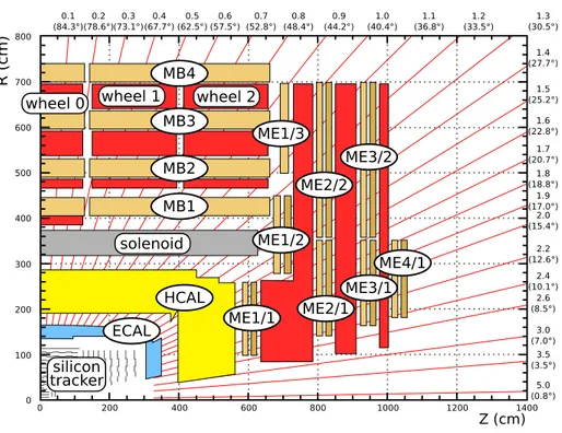
Figure 1. Schematic view of a CMS quadrant.
arranged as a 12-sided cylinder (each side is called a sector) closed at each end by endcaps. The barrel yoke is subdivided into five wheels (YB0, YB±1, and YB±2) and each endcap yoke into three disks (YE±1, YE±2, and YE±3). Three technologies are used for the detection of muons: drift tubes (DT) in the central region, cathode strip chambers (CSC) in the endcaps, and resistive plate chambers (RPC) throughout barrel and endcap. The DT system comprises 250 chambers mounted onto the five wheels of the barrel yoke and arranged into four concentric layers, called muon barrel (MB) stations, interleaved with the steel yoke plates. The CSC system consists of 468 chambers mounted on the endcap disks, perpendicular to the beam pipe, and arranged in four layers, called muon endcap (ME) stations, in each endcap. The RPCs are not aligned by the muon alignment system. Figure 1 shows the barrel wheels, endcap disks, and muon stations for one quadrant of the CMS detector.
With the exception of the central wheel, which is fixed, the other wheels and disks are mov-able along the beam direction to allow opening the yoke for the installation and maintenance of the detectors. Gravitational distortions lead to static deformations of the yoke elements that gen-erate displacements of the muon chambers with respect to their design position of up to several millimetres. These displacements can be measured within a few hundred microns by photogram-metry when the detector is open. Similarly, CSC chambers can be located by photogramphotogram-metry to a few hundred microns within the disks in the plane perpendicular to the beam line. However, the repositioning of the large elements of the yoke after opening and closing of the CMS detec-tor, though rather precise, cannot be better than a few millimetres given their size and weight. In addition, the magnetic flux induces huge forces that cause deformations and movements that may be as large as several millimetres, and must be carefully tracked by the alignment system. The
2010 JINST 5 T03019
eleven yoke elements are compressed and slightly tilted. The endcap disks are bent, and the central part of the YE±1 disks is deflected inward by roughly 15 mm. Thermal equilibrium of the yoke is reached after several months of operation, with thermal effects expected in the sub-millimetre range. Thermal effects will be studied in the future when CMS runs over long periods of time under stable detector conditions. All these displacements and deformations are either partially or totally non-reproducible, and their typical size is an order of magnitude larger than the desired chamber position accuracy.
In order to determine the positions and orientations of the muon chambers, the CMS alignment strategy combines precise survey and photogrammetry information, measurements from an optical-based muon alignment system, and the results of alignment procedures optical-based on muon tracks. The muon alignment system discussed in this paper is fast, independent of beam conditions, and can provide online monitoring of relative movements precisely. Track-based alignment needs to accu-mulate a large amount of data and is, therefore, intrinsically slower, but it provides very accurate alignment of the muon chambers with respect to the inner tracker, which is crucial for optimal muon momentum measurement.
The CMS alignment system consists of four independent parts. Three of these parts deal with the internal alignment of the tracker, DT, and CSC systems. A fourth part, called the Link system, locks all four parts together in a common reference frame, allows simultaneous monitoring of the barrel and endcaps, and monitors the displacements of heavy structures during the critical closing phase and during normal operation. The muon alignment system is designed to provide continu-ous monitoring of the muon chamber positions in the entire magnetic field range between 0 T and 4 T, and to meet the challenging constraints of large radiation and magnetic field tolerance, wide dynamic range, high precision, and tight spatial confinement. The system is based on a number of precise rigid structures independently supported by the tracker and by each yoke element. These structures contain optical sensors that look at the relative positions of chambers within the same yoke element. The connection among the structures located on the various yoke elements is pos-sible only when CMS is closed, and is obtained through a network of laser beams, local distance sensors, and digital cameras.
The aim of the muon alignment system is to provide position information of the detector elements with a precision comparable to the intrinsic chamber resolution. This information is used online for triggering purposes, and offline as a correction for track reconstruction. The internal alignment of tracker elements is described elsewhere [5].
The rest of the paper is organized as follows: section 2 describes the system layout and align-ment strategy common to all three muon alignalign-ment subsystems; section 3 gives a brief description of the data acquisition and data taking experience during CRAFT; sections 4 and 5 present the alignment results for barrel and endcap muon chambers, respectively.
2 System layout and geometry reconstruction
CMS uses a coordinate system with the origin at the nominal collision point, the x-axis pointing to the centre of the LHC, the y-axis pointing up (perpendicular to the LHC plane), and the z-axis along the anticlockwise-beam direction. These global CMS coordinates are denoted as xCMS, yCMS, and
2010 JINST 5 T03019
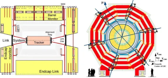
Figure 2. Schematic view of the CMS alignment system. Left: longitudinal view of CMS showing one of
the three rCMS–zCMSalignment planes. The continuous and dashed lines show different optical light paths.
MABs on YB+1 and YB-1 are not shown because they are rotated 30◦ with respect to this plane. Right:
transverse view of the barrel muon detector. The crossing lines indicate the rCMS–zCMS alignment planes
with 60◦staggering in φ . The φ sectors are numbered from 1 to 12 with increasing azimuthal angle, with
sector 1 perpendicular to xCMS.
in the xCMS–yCMS plane, and rCMS is the perpendicular distance from the beam line. Each muon
chamber and layer has its own local coordinate system, centred on the subdetector with zlocalbeing
perpendicular to the measurement planes. The xlocal axis is always the direction measured with
the highest precision, arranged to coincide with the global rφ direction at the chamber origin, and
ylocalcompletes a right-handed local Cartesian coordinate system. In the absence of misalignments,
ylocal is parallel to the beam line for DT chambers and radial for CSC chambers. A sketch of the
local coordinate systems can be found in ref. [4]. Since the magnetic field is parallel to zCMS,
the muon transverse momentum is measured from the curvature of tracks in the rCMS–φCMSplane.
The precision on displacements in the rφ direction and rotations of chambers around their local axis parallel to zCMSis therefore directly related to the momentum resolution. Alignment in other
degrees of freedom affects the momentum measurement as higher-order corrections.
The basic geometrical layout of the muon alignment system consists of three rCMS–zCMS
align-ment planes with 60◦staggering in φ . This segmentation is based on the 12-fold geometry of the barrel muon detector (each φ segment of the DT system is called a sector). Within each plane, dis-tributed networks of optical sensors attached directly to muon chambers or to rigid local structures are connected by laser or LED lines. The optical alignment network is complemented by different types of analog sensors: electrolytic clinometers, optical and mechanical proximity sensors, probes for magnetic field measurement, temperature and humidity sensors. Figure 2 shows schematic longitudinal and transverse views of CMS, with the light paths indicated.
The muon alignment system comprises three subsystems: endcap, barrel and link.
Each muon endcap station is monitored through three radial straight line monitors running along the full diameter of the supporting disks. Each straight line monitor consists of laser beams detected by two optical sensors in each of the four crossed chambers. Approximately one sixth
2010 JINST 5 T03019
of the CSC chambers are directly monitored; the rest are aligned with respect to these monitored chambers by detecting tracks that pass through their overlapping regions. More details are given in section 5.
In the barrel, the positions of the 250 DT chambers are monitored by a network of 36 rigid carbon fibre structures called Modules for the Alignment of the Barrel (MAB), supported by the yoke wheels, and optically connected together once the detector is closed. Six MABs are mounted on each of the two outermost faces of the external wheels (see figure2right) and inside each of the four gaps between the wheels. The external MABs contain link and endcap elements used to refer the three alignment subsystems to each other.
The Link system simultaneously monitors the twelve external MABs and twenty-four CSC chambers located in the first endcap muon station, in YE±1 (twelve per side), and relates them to the tracker volume using laser beams emitted from two rigid carbon fibre structures, called alignment rings, attached to the tracker endcaps. Other sources and optics housed in MABs and link disks complete the light path layout. The link disks are floating structures suspended inside the innermost endcap iron disks (YE±1).
Details on the performance requirements, as well as the design of the subsystems and sensors, can be found elsewhere [1,6]. Each subsystem performs an independent reconstruction, with the link providing a common reference frame. Throughout this paper, geometry reconstruction refers to the determination of the muon chamber positions and orientations.
2.1 Offline geometry reconstruction
The muon alignment system uses a dedicated reconstruction program called CMS Object-oriented Code for Optical Alignment (COCOA) [7–9] to transform the various measurements into a recon-structed DT and CSC aligned geometry. The software reconstructs the position and orientation of the optical system objects and chambers, and performs a full propagation of errors to take into account the correlations between different measurements. For the entire muon alignment system, COCOA works with about 30 000 parameters: ≈ 3000 for the link, ≈ 6500 for the endcap, and ≈ 20 000 for the barrel. The alignment geometry of the chambers and all alignment objects within the system are organized in a hierarchical order using a system description which must be provided in addition to the measurements themselves. This description includes the interconnection of ele-ments, e.g., laser-sensor association, and the system hierarchy, e.g., system elements association to mechanical structures, together with an approximation of the geometry obtained from other mea-surements (calibrations or photogrammetry). Supplying a good estimate of the initial geometry is not necessary, but speeds up the convergence, ensures good quality of the fit results, and helps to avoid falling into local minima.
The starting geometry at B = 0 T uses two types of photogrammetry and optical survey mea-surements:
• photogrammetry measurements of DT and CSC chambers, and alignment components inside the disks and wheels. These measurements are done with an open detector with respect to the disks and wheels themselves (regardless of their position and orientation). The measurement precision per point measured is 300 µm in all three coordinates.
2010 JINST 5 T03019
• Survey measurements, generally performed with theodolites, of the large structures such as wheels and disks after closing the detector and reaching the final position. Theodolite measurements have a similar precision in the measured points as photogrammetry, but the measurement is done in the global CMS reference and in this transformation the precision is lower, so the final coordinates of the large structures have a precision of ≈ 1 mm.
The geometry reconstruction proceeds independently for each alignment subsystem, each having a completely different set of measurements and geometry description, and thus requiring a different fit strategy implemented in COCOA. The output of COCOA contains the best geometrical de-scription of the system compatible with the measurements and with the information from structure calibrations. Propagated uncertainties for all aligned objects are also provided.
2.2 Performance and validation
Alignment results must be validated before they can be used for track reconstruction. For central Drift Tubes, several well established track-based validation techniques are described in ref. [4]. This validation has so far only been performed for the track-based alignment. For endcap Cathode Strip Chambers, the validation procedures are still being developed.
For the optical-based measurements presented in this paper, the accuracy is estimated by com-paring the results from geometry reconstruction at 0 T with photogrammetry measurements. This is the only independent reference used so far to cross-check the results. All the comparisons are done independently for each structure, which is considered more stable under field-induced defor-mations. In the case of the barrel, the central barrel wheel (YB0) is generally used as reference because it is expected to be the most stable structure in CMS.
Care must be taken when comparing photogrammetry measurements, which are taken with an open detector, to alignment measurements after detector closing and before any magnet cycles which can cause permanent movements and deformations of large structures. Such measurements are not always directly comparable, since individual measurements might be biased by residual deformations caused by detector lowering (from the surface to the underground cavern), magnetic and gravitational forces, internal deformations during closing, or thermal effects. It is assumed that, in average, the photogrammetry values and the reconstructed values agree. Under this assumption and in the absence of systematic biases in the reconstruction, the distribution of the difference between photogrammetry and reconstructed positions is expected to have a mean of zero. The deviation from zero is taken as an estimate of the systematic error in the reconstruction.
Until a more precise track-based validation is implemented, the precision of the system is given by the standard error propagation of the geometry reconstruction software, which can be checked from residual distributions of laser hits with the corresponding pull distributions.
3 Data acquisition
The muon alignment data acquisition system is independent of the CMS event flow. Each alignment subsystem consists of entirely different types of sensors and electronics. The time required to record a complete set of data for each subsystem is ≈ 18 minutes for the endcap, ≈ 27 minutes for the link, and ≈ 2 hours for the barrel. The data acquisition program is fully integrated into the
2010 JINST 5 T03019
CMS detector control system. The data are recorded in a dedicated online database, converted into ROOT [10] format, and transfered to the Tier-0 computing centre at CERN. This process was not automated during CRAFT. From the Tier-0, the data are copied to an offline farm where geometry reconstruction is performed.
The knowledge of detector conditions, such as the magnetic field, is of particular importance for the alignment system. The magnetic field cycles during the entire CRAFT period are shown in ref. [3]. The current data taking strategy is to record a full set of alignment measurements at least once per day, under stable conditions. Whenever the magnet ramps up or down, information is recorded only from analog sensors, such as clinometers and proximity sensors, which have an almost instantaneous response, in order to track detector movements and deformations. As the opti-cal sensor cycles are too slow compared to normal ramping times, full data recording during ramps is not practical. Online monitoring tools are being developed in order to provide live information of relative movements of structures directly monitored by analog sensor measurements and, with a maximum delay of two hours, information of relative changes from optical sensors.
The full muon alignment system was exercised for the first time during CRAFT. The data acquisition and transfer, though not entirely automated, were robust and performed without any significant operational problems. Data were systematically recorded during the entire CRAFT period at stable magnetic field values of 0 T and 3.8 T.
A high operational efficiency was achieved. Above 98% of optical sensors were operational for the whole system. System failures were mainly related to laser misalignment. As an example, the closing outside of tolerances of the innermost endcap disk on the −zCMSside caused a conflict
with some of the link alignment components, making the laser system for this part of the detector effectively unusable. Most hardware problems were fixed between the subsequent opening and closing of the detector.
4 Muon barrel alignment
The alignment system [1,6] measures the positions of the DT chambers with respect to each other and to the entire muon barrel. Each DT is equipped with LED light sources, visible from both zCMSdirections, which are observed by small video cameras (600 in total) mounted on the MABs.
MABs located on each of the three alignment planes look in opposite directions at the LEDs on the chambers of two mobile wheels. The MABs between two wheels observe the LEDs of the chambers of both wheels. Direct observations between MABs create also diagonal connections, adding further redundancy and allowing the system to relate measurements from different wheels and sectors. The zCMS coordinate of the MABs is also independently measured with respect to
the outer cylinder of the coil. In addition, in the outermost wheels of the barrel yoke (YB−2 and YB+2) the 3D positions of the MABs are also measured, by the link alignment system, in a global reference system with respect to the tracker volume, and thus their relative positions with respect to the first endcap station are also known.
Although raw data for the whole barrel muon system were collected, a very selective data quality control is required before the raw data can be used for analysis. Automated data quality procedures were not fully developed during CRAFT, so a full geometry reconstruction was not
2010 JINST 5 T03019
possible. Only four out of twelve sectors were analyzed and, therefore, only partial results (relative motions) are presented here.
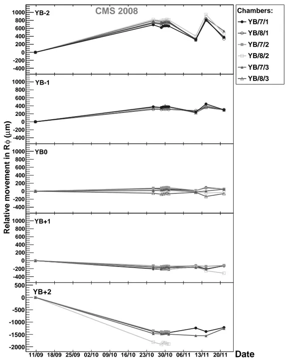
Using two of the analysed sectors, the stability and reproducibility of the muon barrel geom-etry is studied by comparing data taken at different magnetic field strengths. Relative movements in (rφ )CMS with respect to the first measurement at 0 T are shown in figure3for muon stations
1 through 3 in sectors 7 and 8. The typical reconstruction precision in position coordinates is estimated to be 200 µm. During the first rampings of the magnet, large irreversible movements were observed. Movements in rφ between the initial 0 T and 3.8 T are approximately 0.7, 0.4, 0.1, −0.2, and −1.5 mm for wheels YB−2, YB−1, YB0, YB+1 and YB+2, respectively. Correspond-ing movements between the initial 3.8 T and subsequent 0 T runs are smaller: −0.3, −0.1, −0.1, −0.1 and 0.3 mm. The reproducibility between 0 T positions after the initial 3.8 T magnet cycle is within 250 µm. The barrel stability at a constant magnetic field of B = 3.8 T was also studied over a period of one week. In general, the detected movements are below 100 µm, therefore smaller than the estimated reconstructed precision.
In order to validate the measurements of the system, the DT positions reconstructed at 0 T are compared to the positions measured directly by photogrammetry [11]. The comparison was made in a coordinate system defined by the DT in sector 7, station 2, considered as perfectly measured by both methods. The positions of the other chambers were determined with respect to this one. Only DT chambers in YB0 were used because the photogrammetry data for the other wheels include uncertainties of the wheel positions with respect to YB0 and the cumulative error is too large to validate the analysis results. The average error of the differences in position (orientation) is 1.5 mm (1.5 mrad), which are the convolution of photogrammetry and COCOA reconstruction uncertain-ties. In the absence of systematic biases, DT reconstructed positions should agree with photogram-metry within these ranges. The observed differences are well within the quoted uncertainties.
During a test of the magnet [1,12] carried out in 2006, the bottom part of the barrel alignment system was instrumented. With magnetic field forces acting on the detector, a compression of the wheels in zCMS towards the interaction point was observed. This compression was measured for
most of the barrel during CRAFT. The relative changes of the barrel length at different positions were measured by the barrel and link subsystems with respect to two stable references: the outer cylinder of the coil and the tracker volume. The results are summarized in table1. The compres-sion is not uniform and depends on the azimuthal angle, with maximum comprescompres-sion observed at the bottom of the barrel and decreasing towards the top. For the first two rows in the table, the uncertainty of these measurements is 300 µm. The table also shows the compression measured independently by the link alignment from a 3D reconstruction of the MABs located on the external YB+2 wheel. The uncertainty in these measurements is 280 µm, resulting from the convolution of the uncertainties in the reconstruction at B = 0 T and 3.8 T.
5 Muon endcap alignment
The alignment system monitors the positions of a subset of the 468 Cathode Strip Chambers in the two muon endcaps. The system uses transverse laser lines across the face of each yoke disk to measure the deflection in zCMSand longitudinal laser lines to measure the rotation of each yoke disk.
2010 JINST 5 T03019
11/09 18/09 25/09 02/10 09/10 16/10 23/10 30/10 06/11 13/11 20/11 11/09 18/09 25/09 02/10 09/10 16/10 23/10 30/10 06/11 13/11 20/11 -400 -200 0 200 400 600 800 1000 YB-2CMS 2008
11/09 18/09 25/09 02/10 09/10 16/10 23/10 30/10 06/11 13/11 20/11 11/09 18/09 25/09 02/10 09/10 16/10 23/10 30/10 06/11 13/11 20/11 -400 -200 0 200 400 600 800 1000 YB-1 11/09 18/09 25/09 02/10 09/10 16/10 23/10 30/10 06/11 13/11 20/11 11/09 18/09 25/09 02/10 09/10 16/10 23/10 30/10 06/11 13/11 20/11 -400 -200 0 200 400 600 800 1000 YB0 11/09 18/09 25/09 02/10 09/10 16/10 23/10 30/10 06/11 13/11 20/11 11/09 18/09 25/09 02/10 09/10 16/10 23/10 30/10 06/11 13/11 20/11 -400 -200 0 200 400 600 800 1000 YB+1 11/09 18/09 25/09 02/10 09/10 16/10 23/10 30/10 06/11 13/11 20/11 11/09 18/09 25/09 02/10 09/10 16/10 23/10 30/10 06/11 13/11 20/11 -2000 -1500 -1000 -500 0 500 YB+2Date
Chambers: YB/7/1 YB/8/1 YB/7/2 YB/8/2 YB/7/3 YB/8/3 m) µ ( φ Relative movement in RFigure 3. Relative rφ movements of the barrel chambers. Points at 11/09 are the initial 0 T measurements before any magnet cycle. The remaining measurements show the difference in rφ with respect to this initial measurement. The cluster of points near 30/10 correspond to B = 3.8 T. Points near 11/11, 15/11, and 23/11 correspond to B = 0 T, 4 T, and 0 T, respectively. The average precision is ≈ 200 µm for all points.
A complex arrangement of different types of position sensors measures the global rCMS, φCMS,
and zCMScoordinates of one-sixth of all CSC chambers. This allows adequate monitoring of the
yoke disk deformations due to strong magnetic forces. Unmonitored CSC chambers can be coarsely aligned with the average displacements and rotations observed for monitored chambers in the
cor-2010 JINST 5 T03019
Table 1. Compression of the barrel at B = 3.8 T compared to B = 0 T at azimuthal positions of the z-bars. Missing entries are due to hardware failures. The last line corresponds to the compression measured independently by the link alignment.
φCMSposition [◦] 15 75 135 195 255 315 ∆(zCMS) at +zCMSside [mm] −1.7 ± 0.3 - −1.5 ± 0.3 −1.7 ± 0.3 −2.7 ± 0.3 −2.2 ± 0.3 ∆(zCMS) at −zCMSside [mm] 1.3 ± 0.3 1.1 ± 0.3 1.5 ± 0.3 1.6 ± 0.3 1.8 ± 0.3 -Link ∆(zCMS) at +zCMSside [mm] −1.8 ± 0.3 −1.1 ± 0.3 −1.0 ± 0.3 −1.8 ± 0.3 −3.2 ± 0.3 −2.7 ± 0.3 X Y Legend SLM DCOPS SLM Laser Transfer Plate
Transfer Line DCOPS
Straight Line Monitor (SLM) ME2/2_03 ME2/1_02 ME2/2_08 ME2/1_04 ME2/2_15 ME2/1_08 ME2/2_20 ME2/1_10 ME2/2_27 ME2/1_14 ME2/1_16 ME2/2_32 SLM1 SLM2 SLM3 SLM1 SLM2 SLM3 TP 1 TP 2 TP 3 TP 4 TP 5 TP 6 Laser 1 Laser 2 Laser 3 Laser 4 Laser 5 Laser 6
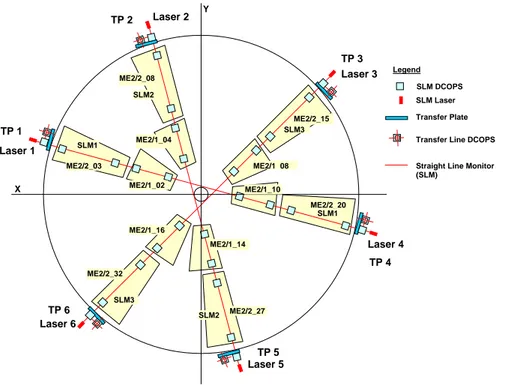
Figure 4. Schematic rφ view of Straight-Line Monitors in the ME2 station. Locations of axial transfer lines running perpendicular to the plane and across endcaps are indicated. Optical sensors and other alignment components are also shown.
responding rings. All CSC alignments are subsequently refined with tracks that traverse overlap-ping chambers. For the ME1/3 chambers, which do not overlap, azimuthal distances between the chambers are additionally monitored by proximity sensors.
Details on the performance requirements and the design of the system and its sensors can be found elsewhere [1, 6, 13]. Here we briefly recall the main features of the system used in this analysis. Three straight-line monitors (SLMs) within the rφ plane of each muon endcap station, as shown in figure4, measure global zCMSand φCMSchamber positions relative to references located
at the outer edges of the stations.
In the ME1 stations, the straight-line monitors cannot reach across the entire endcap yoke disk as they are blocked (by design) by the endcap calorimeters attached to the YE1 yoke disks. Instead of three full-length straight-line monitors, there are six half-length straight-line monitors in each
2010 JINST 5 T03019
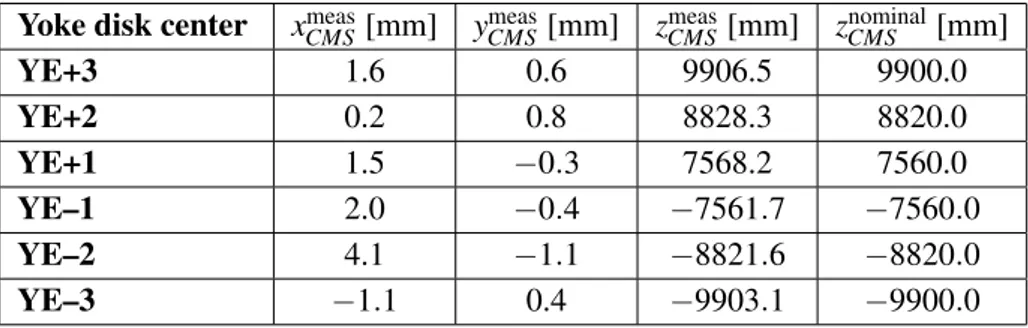
Table 2. Positions of muon endcap yoke disk centers in global CMS coordinates, measured by survey with closed and locked detector before the start of the CRAFT test. Nominal global z-position of yoke disk centers are also shown for comparison (nominal (x,y) coordinates are (0,0) for all yoke disks. The uncertainty for all listed measurements is 0.3 mm.
Yoke disk center xCMSmeas[mm] yCMSmeas[mm] zmeasCMS[mm] znominalCMS [mm]
YE+3 1.6 0.6 9906.5 9900.0 YE+2 0.2 0.8 8828.3 8820.0 YE+1 1.5 −0.3 7568.2 7560.0 YE–1 2.0 −0.4 −7561.7 −7560.0 YE–2 4.1 −1.1 −8821.6 −8820.0 YE–3 −1.1 0.4 −9903.1 −9900.0
ME1 station. Each half straight-line monitor observes two chambers (one in the ME1/2 ring and one in the outer ME1/3 ring) and connects to the link alignment laser lines at the inner radius and to the Barrel MABs at the outer radius. The geometry of the ME4 straight-line monitors is identical to those on the ME2,3 stations despite the absence of the outer ring of ME4/2 chambers. This identical design is intended as a preparation for a future planned CMS upgrade that will add outer ME4/2 chambers.
Optical transfer lines run parallel to the CMS z-axis along the outer cylinder envelope of CMS, at six angles separated by 60◦in φCMS. These axial lines provide an optical connection between the
forward and backward muon endcaps, across the barrel wheels. Distancemeters, mounted around the periphery of each ME station, measure the zCMS location of the outer edge of the ME stations
relative to the external MAB positions on the YB2 wheels. 5.1 Reconstruction of CSC positions
The analysis of CRAFT data focuses on determining CSC chamber positions in global zCMSand
rotations φxlocalaround their local x-axes. This complements track-based alignment, which is mainly
suitable for alignment in the (rφ )CMSplane [4].
5.1.1 Chamber positions in stations ME2,3,4 measured with straight-line monitors
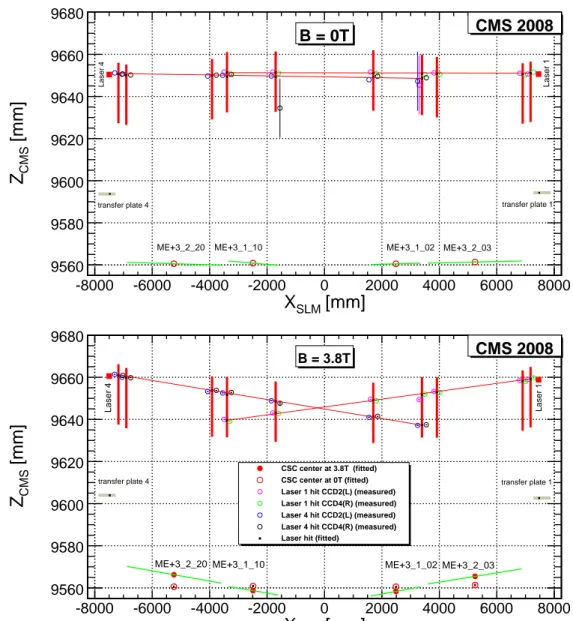
The geometry reconstruction starts with performing the basic alignment procedure described in section 2, which is common to all subsystems. Measurements taken at B = 0 T are used for the reconstruction of CSC positions. An example of such a reconstruction in zCMSat B = 0 T is shown
for one straight-line monitor in figure5 (top). The discrepancies in zCMS between reconstructed
values and photogrammetry measurements are shown in figure 6 (left) for all ME2,3,4 stations. After the comparison with photogrammetry, the endcap reconstruction proceeds to reconstruct the absolute zCMSpositions of all monitored CSC chambers at B = 3.8 T, using as input field-on sensor
measurements, the absolute zCMSpositions of the endcap yoke disk centers provided by survey [14]
and listed in table2, and the relative zCMS-displacements measured between B = 0 T and B = 3.8 T.
As an example of field-on reconstruction results, figure5(bottom) shows the reconstruction for the straight-line monitor between transfer plates 1 and 4 in ME+3 at B = 3.8 T. Comparing this result
2010 JINST 5 T03019
[mm]
SLMX
-8000 -6000 -4000 -2000 0 2000 4000 6000 8000[mm]
CMSZ
9560 9580 9600 9620 9640 9660 9680 CMS 2008 B = 0T Laser 1 Laser 4ME+3_1_10 ME+3_1_02 ME+3_2_03 ME+3_2_20
transfer plate 1
Nominal top of first CSC PCB panels (’skin’) transfer plate 4 nom. SLM center
[mm]
SLMX
-8000 -6000 -4000 -2000 0 2000 4000 6000 8000[mm]
CMSZ
9560 9580 9600 9620 9640 9660 9680 CSC center at 3.8T (fitted) CSC center at 0T (fitted) Laser 1 hit CCD2(L) (measured) Laser 1 hit CCD4(R) (measured) Laser 4 hit CCD2(L) (measured) Laser 4 hit CCD4(R) (measured) Laser hit (fitted)CMS 2008
B = 3.8T
Laser 1
Laser 4
ME+3_1_10 ME+3_1_02 ME+3_2_03 ME+3_2_20
transfer plate 1 transfer plate 4
Figure 5. Reconstruction results for positions of chambers and sensors in zCMSvs. their positions xSLMalong
a straight-line monitor at B = 0 T (top) and 3.8 T (bottom). The data shown are for the straight-line monitor connecting transfer plates 1 and 4 of station ME+3. Large vertical bars indicate fitted positions of optical sensors. Laser hits on optical sensors are indicated by open circles with error bars on hit positions smaller than marker symbols. Long near-horizontal lines represent fitted laser beams. Reconstructed CSC chamber tilts are indicated by the short near-horizontal lines.
with the reconstruction for the same straight-line monitor at B = 0 T (figure5 top) demonstrates that the endcap yoke disk bends due to magnetic forces. Analogous reconstruction plots for data taken at B = 3.8 T with the other straight-line monitors show similar deformations of all yoke disks towards the interaction point by about 10 to 12 mm for the chambers on the inner rings and by about 5 mm away from the interaction point for the chambers in the outer ring.
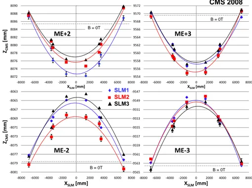
We summarize our reconstruction results for the ME2,3 stations in figure 7. The yoke disk
2010 JINST 5 T03019
Constant 16.7 ± 0.4 Mean 0.3447 ± 0.0335 Sigma 1.318 ± 0.043 ) [mm] CMS Discrepancy in Z (Fitted - PG in Z -5 -4 -3 -2 -1 0 1 2 3 4 5 0 5 10 15 20 25 Constant 16.7 ± 0.4 Mean 0.3447 ± 0.0335 Sigma 1.318 ± 0.043 CMS 2008 Mean -0.5915 RMS 1.344for DCOPS and chamber centres [mm]
CMS Cocoa fit - PG of Z -3 -2 -1 0 1 2 3 0 0.5 1 1.5 2 2.5 3 Mean -0.5915 RMS 1.344 CMS 2008
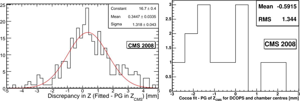
Figure 6. Discrepancies ∆zCMS between zCMS-positions reconstructed by COCOA and measured by
pho-togrammetry (PG) at B = 0 T. Left: For CSC centres, alignment pins, and optical sensors in ME2,3,4 stations using full straight-line monitors fitted with a Gaussian. Right: For CSC centres and optical sensors in ME+1 station using half straight-line monitors.
deformations shown in this figure are calculated from the differences of reconstructed positions of the CSC alignment pins at B = 0 and 3.8 T. Quadratic fits describe the yoke disk deformations reasonably well. These results are consistent with ME+2 reconstruction results using first magnet test data taken in 2006 at 4 T [15]. The differences observed by different straight-line monitors for the same station indicate a slightly asymmetric deformation of the yoke disks. Some asymmetry is expected because the endcap yoke disks are fixated at the bottom to massive carriage structures that are used to move the yoke disks as needed.
The precision of the reconstruction is estimated from COCOA’s error propagation to be 280 µm and 320 µm in zCMSfor the inner and outer rings of chambers, respectively, and 200 µrad
in φxlocal. The angular uncertainty has a contribution from the error in zCMSand the chamber length.
Figure6(left) shows the difference ∆zCMSbetween zCMS-positions reconstructed by COCOA and
measured by photogrammetry at B = 0 T for CSC centers, alignment pins, and optical sensors in ME2,3,4 stations using full straight-line monitors. We take the deviation from zero of the mean of this distribution as a measure of the systematic error of the COCOA reconstruction, i.e. σsyst(zCMS) = 340 µm. The photogrammetry measurements used in this comparison spread over
a significant time period of two years. Some measurements were done on the surface and some in the underground CMS cavern. The deviations are therefore an upper limit. Reconstruction at B = 3.8 T cannot be checked against independent survey or photogrammetry because those cannot be performed for a closed detector when the magnetic field is turned on. Consequently, we explic-itly assume that the COCOA reconstruction of CSC positions at B = 3.8 T has very similar errors as the B = 0 T reconstruction, because the same reconstruction method is applied in both cases.
5.1.2 Chamber positions in ME1
The reconstruction of CSC positions in ME1 using half straight-line monitor data is more complex than the reconstruction of full-length straight-line monitors in ME2,3,4, because additional infor-mation from the link alignment is required. We use the zCMSof MABs reconstructed by the link
2010 JINST 5 T03019
8072 8074 8076 8078 8080 8082 8084 8086 8088 8090 -8000 -6000 -4000 -2000 0 2000 4000 6000 8000 ZCMS [mm ] XSLM[mm] B = 0T 9554 9556 9558 9560 9562 9564 9566 9568 9570 9572 -8000 -6000 -4000 -2000 0 2000 4000 6000 8000 XSLM[mm] -8081 -8079 -8077 -8075 -8073 -8071 -8069 -8067 -8065 -8063 -8000 -6000 -4000 -2000 0 2000 4000 6000 8000 ZCMS [mm ] XSLM[mm] -9565 -9563 -9561 -9559 -9557 -9555 -9553 -9551 -9549 -9547 -8000 -6000 -4000 -2000 0 2000 4000 6000 8000 XSLM[mm] ♦ SLM1 ■ SLM2 ▲ SLM3 ME+2 ME-3 ME-2 ME+3 CMS 2008 B = 0T B = 0T B = 0TFigure 7. Yoke disk deformations at B = 3.8 T in ME2 and ME3 stations measured with straight-line monitors. Points shown correspond to positions of CSC alignment pins and are fitted with second order
polynomials. Error bars correspond to σtot(zCMS) = 470 µm and apply to all measurement points. For clarity,
error bars are shown only for the lowest curve in each station. Dashed lines indicate the average alignment pin positions at B = 0 T for the three SLMs in each station as measured by photogrammetry and survey.
For the ME1/1 and ME1/2 chambers, xCMS, yCMS, and zCMScoordinates as well as the chamber
rotations φCMSand φxlocal, around their local x-axes, are obtained from the reconstruction of the link
sensors data. The reconstruction procedure is described in ref. [12]. Using global x, y, z coordinate information from link sensors inside the half straight-line monitor, together with global x, y infor-mation from transfer lines, the ME1/3 chambers can be located accurately and the measurements of the ME1/2 chamber positions provided by the link system can be refined. For the CRAFT exer-cise, adequate transfer line information was not available, so the xCMS, yCMScoordinates were not
reconstructed at B = 3.8 T, and the alignment focused on measuring the zCMScoordinates.
Note that six ME1/2 chambers are reconstructed independently by both the link and endcap systems. The relative field-on to field-off movement for these chambers is in very good agreement, with an average difference between the two systems below 30 µm in xCMSand yCMS, and below
190 µm in zCMS. Absolute reconstructed positions agree within 470 µm.
The precision of the ME1 reconstruction using the half straight-line monitors is estimated from COCOA’s error propagation. For ME1/2 and ME1/3 chambers the error in xCMS and yCMS
is 260 µm. The errors in zCMS are 275 µm and 345 µm for the ME1/2 and ME1/3 chambers,
respectively. We compare the results of the B = 0 T fit to photogrammetry measurements for ME+1, figure6(right), and take the deviation from zero of the mean of this distribution as a measure of the systematic error of the COCOA reconstruction, i.e. σME+1
syst (zCMS) = 590 µm. Following the same
procedure for the reconstruction of the link system data, the estimated errors on the determination
2010 JINST 5 T03019
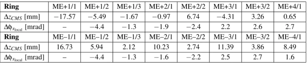
Table 3. Average alignment corrections ∆zCMS= zrecoCMS− zCMSnominalto CSC chamber positions and orientations
for each ring with respect to nominal. The typical precisions are described in the text. Dashes in the table indicate degrees of freedom not measured by the system.
Ring ME+1/1 ME+1/2 ME+1/3 ME+2/1 ME+2/2 ME+3/1 ME+3/2 ME+4/1
∆zCMS[mm] −17.57 −5.49 −1.67 −0.97 6.74 −4.31 3.26 0.65
∆φxlocal[mrad] – −4.4 −1.3 −1.9 −2.4 2.2 2.6 2.7
Ring ME–1/1 ME–1/2 ME–1/3 ME–2/1 ME–2/2 ME–3/1 ME–3/2 ME–4/1
∆zCMS[mm] 16.73 5.94 2.12 10.23 2.74 11.39 3.86 8.49
∆φxlocal[mrad] – −4.4 −1.3 −1.6 −2.2 2.5 2.7 1.6
of the positions of the ME1/1 and ME1/2 chambers in global x, y, z coordinates are 140 and 220 µm for B = 0 T and B = 3.8 T fits, respectively. COCOA propagation of angular uncertainties estimates an error of 30 µrad for angular measurements. By comparing the results of the B = 0 T fit to photogrammetry measurements for ME+1 we measure a systematic bias at the level of 35 µm for positions and 35 µrad for angles.
5.2 Endcap alignment constants
For those CSC chambers that are not directly monitored by straight-line monitors, the average of the zCMS-positions and φxlocal-tilts obtained from the monitored chambers are used as alignment
corrections in the corresponding rings. This is reasonable since we find approximate azimuthal symmetry in the yoke disk deformation (figure7). The average alignment corrections with respect to the nominal geometry are listed for each CSC ring in table3and visualized as a sketch in figure8. Due to different initial positions of the forward and backward endcap yoke disks relative to nominal (see table2) the CSC alignment corrections to zCMSwith respect to nominal CSC positions are not
symmetric between the two endcaps, even though the bending itself is similar for forward and back-ward muon stations. The CSC alignment constants described here together with complementary constants for the other coordinates (rφ positions), obtained from track-based muon alignment [4], are used for the reconstruction of cosmic ray muon tracks in the CRAFT exercise [16].
6 Summary
The muon alignment system successfully recorded data during the CRAFT 2008 exercise. The results obtained show several achievements as well as some shortcomings which are being or have already been addressed. All three subsystems are able to track detector movements and deforma-tions under magnetic forces, and monitor the stability of the detector during operation. Results from the three subsystems are in agreement with each other and with photogrammetry measurements, where these apply.
For the DT chambers, only four (out of twelve) sectors in only one (out of five) wheels were aligned relative to a fixed DT chamber. Although a complete alignment geometry was not achieved, initial partial reconstruction of active planes and studies of stability show promising results. Initial
2010 JINST 5 T03019
Nominal CSC position ← Muon Endcap stations → ME+1 ME+2ME+3 ME1 ME2 ME3 ME4
z CMS r CMS CMS Side view Ä Ä Ä Ä Ä Ä Ä Ä Ä Ä Ä Ä Nominal CSC position Ä Ä Ä Ä Ä Ä Ä Ä Ä Ä Ä Ä j x = 0 Not to Scale ! Ä Ä Ä Ä Red: Aligned by TrackerMuon Link system Blue: Aligned by optical DCOPS & analog Zsensors <j x >: 2.6mrad <Δz ME+1/1 >: 17.57 mm <Δz ME1/1 >: 16.73 mm Ä Ä nom. <Δz ME+1/2 >: 5.49 mm Ä <Δz ME1/2 >: 5.94 mm Ä <Δz ME2/1 >: 10.23 mm <Δz ME3/1 >: 11.39 mm <Δz ME4/1 >: 8.49 mm <Δz ME+2/1 >: 0.97 mm <Δz ME+3/1 >: 4.31 mm <Δz ME+4/1 >: 0.65 mm <j x >: 2.4mrad <j x >: 1.9mrad <j x >: 2.2mrad <j x >: 2.7mrad <j x >: 1.6mrad <j x >: 2.5mrad <j x >: 1.6mrad <j x >: 2.7mrad <j x >: 2.2mrad nom. <j x >: 4.4mrad < j x >: 4.4mrad ME+4 <Δz ME+2/2 >: 6.74 mm <Δz ME+3/2 >: 3.26 mm <Δz ME2/2 >: 2.74 mm <Δz ME3/2 >: 3.86 mm
B=3.8T
<Δz ME+1/3 >: 1.67 mm <Δz ME1/3 >: 2.12 mm <j x >: 1.3mrad <j x >: 1.3mrad Ä X local CMS 2008Figure 8. Summary sketch of average deformations and displacements from nominal positions for muon endcap stations at B = 3.8 T during CRAFT exercise, as observed with the muon alignment system. The
shown displacements ∆zCMS and rotations φxlocal are averages over the six monitored CSC chambers in
each ring.
reconstructions at B = 0 T agree with photogrammetry within uncertainties. Stability under nom-inal field and reproducibility of reconstructed positions at 0 T after full magnetic field cycles are observed at a level smaller or comparable to the estimated reconstruction precision of 200 µm.
For the CSC chambers, all monitored chambers were aligned in zCMSand φxlocal, with the
ex-ception of the ME1/1 chambers, which were aligned only in zCMS. Alignment of the CSC chambers
for the remaining degrees of freedom, in particular for xCMSand yCMS, which are crucial for
mo-mentum reconstruction, is in progress. An aligned detector geometry at B = 3.8 T is provided in the form of alignment constants which are used for muon track reconstruction. The precision for ME2, ME3, and ME4 chambers ranges between 280 and 320 µm in zCMS, and is approximately
200 µrad in φxlocal. For the ME1 chambers, the precision in zCMSranges between 220 and 340 µm
from inner to outer rings. The systematic error associated with the reconstruction is estimated to be below 500 µm from comparison with photogrammetry.
Alignment precisions are summarized in table 4. The muon alignment system was partly commissioned during CRAFT. Even if a complete muon alignment reconstruction was not ready, it has proved its capability to provide DT and CSC chamber alignment with a precision close to that required by CMS. Most of the system failures have subsequently been fixed, and initial results for a complete alignment of DT and CSC chambers is already available in 2009. A very precise and accurate muon alignment is expected in the near future by combining results from the muon alignment system with those from the alignment based on tracks.
2010 JINST 5 T03019
Table 4. Typical precisions obtained for DT and CSC chamber alignment. Dashes in the table indicate degrees of freedom not yet measured by the system. Of the reconstructed degrees of freedom, the most
relevant for momentum measurement is rφCMS, the remaining affecting the momentum reconstruction as a
higher-order correction.
Chamber rφCMS[µm] zCMS[µm] φxlocal [µrad]
DT 200 – –
CSC ME1 – 220–340 –
CSC ME2,3,4 – 280–320 200
Acknowledgments
We thank the technical and administrative staff at CERN and other CMS Institutes, and ac-knowledge support from: FMSR (Austria); FNRS and FWO (Belgium); CNPq, CAPES, FAPERJ, and FAPESP (Brazil); MES (Bulgaria); CERN; CAS, MoST, and NSFC (China); COLCIEN-CIAS (Colombia); MSES (Croatia); RPF (Cyprus); Academy of Sciences and NICPB (Estonia); Academy of Finland, ME, and HIP (Finland); CEA and CNRS/IN2P3 (France); BMBF, DFG, and HGF (Germany); GSRT (Greece); OTKA and NKTH (Hungary); DAE and DST (India); IPM (Iran); SFI (Ireland); INFN (Italy); NRF (Korea); LAS (Lithuania); CINVESTAV, CONACYT, SEP, and UASLP-FAI (Mexico); PAEC (Pakistan); SCSR (Poland); FCT (Portugal); JINR (Arme-nia, Belarus, Georgia, Ukraine, Uzbekistan); MST and MAE (Russia); MSTDS (Serbia); MICINN and CPAN (Spain); Swiss Funding Agencies (Switzerland); NSC (Taipei); TUBITAK and TAEK (Turkey); STFC (United Kingdom); DOE and NSF (USA). Individuals have received support from the Marie-Curie IEF program (European Union); the Leventis Foundation; the A. P. Sloan Founda-tion; and the Alexander von Humboldt Foundation.
References
[1] CMS collaboration, The CMS experiment at the CERN LHC,2008 JINST 3 S08004.
[2] L. Evans and P. Bryant eds., LHC Machine,2008 JINST 3 S08001.
[3] CMS collaboration, Commissioning of the CMS experiment and the cosmic run at four tesla,2010
JINST 5 T03001.
[4] CMS collaboration, Alignment of the CMS muon system with cosmic-ray and beam-halo muons,2010
JINST 5 T03020.
[5] CMS collaboration, Alignment of the CMS silicon tracker during commissioning with cosmic rays,
2010 JINST 5 T03009.
[6] CMS collaboration, The Muon Project Technical Design Report, CERN Report CERN-LHCC-97-32
(1997),http://cmsdoc.cern.ch/ftp/TDR/MUON/muon.html
[7] P. Arce and A. L´opez-Virto, CMS Object Oriented Code for Optical Alignment (COCOA),
CMS-NOTE-2002-060(2002).
[8] P. Arce, Object Oriented Software for Simulation and Reconstruction of Big Alignment Systems, Proc.
2010 JINST 5 T03019
[9] P. Arce, Object Oriented Software for Simulation and Reconstruction of Big Alignment Systems, Proc.
of 6thInternational Workshop on Accelerator Alignment (IWAA), Grenoble, France (1999).
[10] R. Brun and F. Rademakers, ROOT - An Object Oriented Data Analysis Framework,Nucl. Instum.
Meth.A 389 (1997) 81;http://root.cern.ch/.
[11] R. Goudard, J.D. Maillefaud and A. Maurisset, CMS BARREL YOKE YB0 Z- Side and Z+ side Muon
chambers, HBs, OVT and MABs coordinates, Survey Report, EDMS 836406,CMS-SG-UR-0078
(2008).
[12] L.A. Garcia-Moral et al., Motions of CMS Detector structures due to the magnetic field forces as
observed by the Link Alignment System during the test of the 4 Tesla magnet solenoid,Nucl. Instrum.
Meth.A 606 (2009) 3.
[13] M. Hohlmann et al., Design and Performance of the Alignment System for the CMS Muon Endcaps,
Proc. IEEE Nucl. Sci. Symp. 2006, San Diego, U.S.A., CMS Conference ReportCR-2008-016(2008).
[14] R. Goudard, J.D. Maillefaud and A. Maurisset, CMS-Yoke Endcaps Opening of all the Endcaps
position check after CRAFT, Survey Report, EDMS 982666,CMS-SG-UR-0124(2009).
[15] M. Hohlmann et al., Aligning the CMS Muon Endcap Detector with a System of Optical Sensors,
Proc. IEEE Nucl. Sci. Symp. 2007, Honolulu, U.S.A., CMS Conference ReportCR-2008-015(2008).
[16] CMS collaboration, Performance of CMS muon reconstruction in cosmic-ray events,2010 JINST 5
T03022.
2010 JINST 5 T03019
The CMS collaborationYerevan Physics Institute, Yerevan, Armenia S. Chatrchyan, V. Khachatryan, A.M. Sirunyan
Institut f ¨ur Hochenergiephysik der OeAW, Wien, Austria
W. Adam, B. Arnold, H. Bergauer, T. Bergauer, M. Dragicevic, M. Eichberger, J. Er¨o, M. Friedl, R. Fr¨uhwirth, V.M. Ghete, J. Hammer1, S. H¨ansel, M. Hoch, N. H¨ormann, J. Hrubec, M. Jeitler, G. Kasieczka, K. Kastner, M. Krammer, D. Liko, I. Magrans de Abril, I. Mikulec, F. Mittermayr, B. Neuherz, M. Oberegger, M. Padrta, M. Pernicka, H. Rohringer, S. Schmid, R. Sch¨ofbeck, T. Schreiner, R. Stark, H. Steininger, J. Strauss, A. Taurok, F. Teischinger, T. Themel, D. Uhl, P. Wagner, W. Waltenberger, G. Walzel, E. Widl, C.-E. Wulz
National Centre for Particle and High Energy Physics, Minsk, Belarus
V. Chekhovsky, O. Dvornikov, I. Emeliantchik, A. Litomin, V. Makarenko, I. Marfin, V. Mossolov, N. Shumeiko, A. Solin, R. Stefanovitch, J. Suarez Gonzalez, A. Tikhonov
Research Institute for Nuclear Problems, Minsk, Belarus A. Fedorov, A. Karneyeu, M. Korzhik, V. Panov, R. Zuyeuski Research Institute of Applied Physical Problems, Minsk, Belarus P. Kuchinsky
Universiteit Antwerpen, Antwerpen, Belgium
W. Beaumont, L. Benucci, M. Cardaci, E.A. De Wolf, E. Delmeire, D. Druzhkin, M. Hashemi, X. Janssen, T. Maes, L. Mucibello, S. Ochesanu, R. Rougny, M. Selvaggi, H. Van Haevermaet, P. Van Mechelen, N. Van Remortel
Vrije Universiteit Brussel, Brussel, Belgium
V. Adler, S. Beauceron, S. Blyweert, J. D’Hondt, S. De Weirdt, O. Devroede, J. Heyninck, A. Kalogeropoulos, J. Maes, M. Maes, M.U. Mozer, S. Tavernier, W. Van Doninck1, P. Van Mulders, I. Villella
Universit´e Libre de Bruxelles, Bruxelles, Belgium
O. Bouhali, E.C. Chabert, O. Charaf, B. Clerbaux, G. De Lentdecker, V. Dero, S. Elgammal, A.P.R. Gay, G.H. Hammad, P.E. Marage, S. Rugovac, C. Vander Velde, P. Vanlaer, J. Wickens Ghent University, Ghent, Belgium
M. Grunewald, B. Klein, A. Marinov, D. Ryckbosch, F. Thyssen, M. Tytgat, L. Vanelderen, P. Verwilligen
Universit´e Catholique de Louvain, Louvain-la-Neuve, Belgium
S. Basegmez, G. Bruno, J. Caudron, C. Delaere, P. Demin, D. Favart, A. Giammanco, G. Gr´egoire, V. Lemaitre, O. Militaru, S. Ovyn, K. Piotrzkowski1, L. Quertenmont, N. Schul
Universit´e de Mons, Mons, Belgium N. Beliy, E. Daubie
Centro Brasileiro de Pesquisas Fisicas, Rio de Janeiro, Brazil G.A. Alves, M.E. Pol, M.H.G. Souza
2010 JINST 5 T03019
Universidade do Estado do Rio de Janeiro, Rio de Janeiro, Brazil
W. Carvalho, D. De Jesus Damiao, C. De Oliveira Martins, S. Fonseca De Souza, L. Mundim, V. Oguri, A. Santoro, S.M. Silva Do Amaral, A. Sznajder
Instituto de Fisica Teorica, Universidade Estadual Paulista, Sao Paulo, Brazil T.R. Fernandez Perez Tomei, M.A. Ferreira Dias, E. M. Gregores2, S.F. Novaes Institute for Nuclear Research and Nuclear Energy, Sofia, Bulgaria
K. Abadjiev1, T. Anguelov, J. Damgov, N. Darmenov1, L. Dimitrov, V. Genchev1, P. Iaydjiev, S. Piperov, S. Stoykova, G. Sultanov, R. Trayanov, I. Vankov
University of Sofia, Sofia, Bulgaria
A. Dimitrov, M. Dyulendarova, V. Kozhuharov, L. Litov, E. Marinova, M. Mateev, B. Pavlov, P. Petkov, Z. Toteva1
Institute of High Energy Physics, Beijing, China
G.M. Chen, H.S. Chen, W. Guan, C.H. Jiang, D. Liang, B. Liu, X. Meng, J. Tao, J. Wang, Z. Wang, Z. Xue, Z. Zhang
State Key Lab. of Nucl. Phys. and Tech., Peking University, Beijing, China Y. Ban, J. Cai, Y. Ge, S. Guo, Z. Hu, Y. Mao, S.J. Qian, H. Teng, B. Zhu Universidad de Los Andes, Bogota, Colombia
C. Avila, M. Baquero Ruiz, C.A. Carrillo Montoya, A. Gomez, B. Gomez Moreno, A.A. Ocampo Rios, A.F. Osorio Oliveros, D. Reyes Romero, J.C. Sanabria
Technical University of Split, Split, Croatia
N. Godinovic, K. Lelas, R. Plestina, D. Polic, I. Puljak University of Split, Split, Croatia
Z. Antunovic, M. Dzelalija
Institute Rudjer Boskovic, Zagreb, Croatia V. Brigljevic, S. Duric, K. Kadija, S. Morovic University of Cyprus, Nicosia, Cyprus
R. Fereos, M. Galanti, J. Mousa, A. Papadakis, F. Ptochos, P.A. Razis, D. Tsiakkouri, Z. Zinonos National Institute of Chemical Physics and Biophysics, Tallinn, Estonia
A. Hektor, M. Kadastik, K. Kannike, M. M¨untel, M. Raidal, L. Rebane Helsinki Institute of Physics, Helsinki, Finland
E. Anttila, S. Czellar, J. H¨ark¨onen, A. Heikkinen, V. Karim¨aki, R. Kinnunen, J. Klem, M.J. Kortelainen, T. Lamp´en, K. Lassila-Perini, S. Lehti, T. Lind´en, P. Luukka, T. M¨aenp¨a¨a, J. Nysten, E. Tuominen, J. Tuominiemi, D. Ungaro, L. Wendland
Lappeenranta University of Technology, Lappeenranta, Finland K. Banzuzi, A. Korpela, T. Tuuva
Laboratoire d’Annecy-le-Vieux de Physique des Particules, IN2P3-CNRS, Annecy-le-Vieux, France
P. Nedelec, D. Sillou
2010 JINST 5 T03019
DSM/IRFU, CEA/Saclay, Gif-sur-Yvette, France
M. Besancon, R. Chipaux, M. Dejardin, D. Denegri, J. Descamps, B. Fabbro, J.L. Faure, F. Ferri, S. Ganjour, F.X. Gentit, A. Givernaud, P. Gras, G. Hamel de Monchenault, P. Jarry, M.C. Lemaire, E. Locci, J. Malcles, M. Marionneau, L. Millischer, J. Rander, A. Rosowsky, D. Rousseau, M. Titov, P. Verrecchia
Laboratoire Leprince-Ringuet, Ecole Polytechnique, IN2P3-CNRS, Palaiseau, France S. Baffioni, L. Bianchini, M. Bluj3, P. Busson, C. Charlot, L. Dobrzynski, R. Granier de Cassagnac, M. Haguenauer, P. Min´e, P. Paganini, Y. Sirois, C. Thiebaux, A. Zabi
Institut Pluridisciplinaire Hubert Curien, Universit´e de Strasbourg, Universit´e de Haute Alsace Mulhouse, CNRS/IN2P3, Strasbourg, France
J.-L. Agram4, A. Besson, D. Bloch, D. Bodin, J.-M. Brom, E. Conte4, F. Drouhin4, J.-C. Fontaine4, D. Gel´e, U. Goerlach, L. Gross, P. Juillot, A.-C. Le Bihan, Y. Patois, J. Speck, P. Van Hove Universit´e de Lyon, Universit´e Claude Bernard Lyon 1, CNRS-IN2P3, Institut de Physique Nucl´eaire de Lyon, Villeurbanne, France
C. Baty, M. Bedjidian, J. Blaha, G. Boudoul, H. Brun, N. Chanon, R. Chierici, D. Contardo, P. Depasse, T. Dupasquier, H. El Mamouni, F. Fassi5, J. Fay, S. Gascon, B. Ille, T. Kurca, T. Le Grand, M. Lethuillier, N. Lumb, L. Mirabito, S. Perries, M. Vander Donckt, P. Verdier
E. Andronikashvili Institute of Physics, Academy of Science, Tbilisi, Georgia N. Djaoshvili, N. Roinishvili, V. Roinishvili
Institute of High Energy Physics and Informatization, Tbilisi State University, Tbilisi, Georgia
N. Amaglobeli
RWTH Aachen University, I. Physikalisches Institut, Aachen, Germany
R. Adolphi, G. Anagnostou, R. Brauer, W. Braunschweig, M. Edelhoff, H. Esser, L. Feld, W. Karpinski, A. Khomich, K. Klein, N. Mohr, A. Ostaptchouk, D. Pandoulas, G. Pierschel, F. Raupach, S. Schael, A. Schultz von Dratzig, G. Schwering, D. Sprenger, M. Thomas, M. Weber, B. Wittmer, M. Wlochal
RWTH Aachen University, III. Physikalisches Institut A, Aachen, Germany
O. Actis, G. Altenh¨ofer, W. Bender, P. Biallass, M. Erdmann, G. Fetchenhauer1, J. Frangenheim, T. Hebbeker, G. Hilgers, A. Hinzmann, K. Hoepfner, C. Hof, M. Kirsch, T. Klimkovich, P. Kreuzer1, D. Lanske†, M. Merschmeyer, A. Meyer, B. Philipps, H. Pieta, H. Reithler, S.A. Schmitz, L. Sonnenschein, M. Sowa, J. Steggemann, H. Szczesny, D. Teyssier, C. Zeidler
RWTH Aachen University, III. Physikalisches Institut B, Aachen, Germany
M. Bontenackels, M. Davids, M. Duda, G. Fl¨ugge, H. Geenen, M. Giffels, W. Haj Ahmad, T. Hermanns, D. Heydhausen, S. Kalinin, T. Kress, A. Linn, A. Nowack, L. Perchalla, M. Poettgens, O. Pooth, P. Sauerland, A. Stahl, D. Tornier, M.H. Zoeller
Deutsches Elektronen-Synchrotron, Hamburg, Germany
M. Aldaya Martin, U. Behrens, K. Borras, A. Campbell, E. Castro, D. Dammann, G. Eckerlin, A. Flossdorf, G. Flucke, A. Geiser, D. Hatton, J. Hauk, H. Jung, M. Kasemann, I. Katkov, C. Kleinwort, H. Kluge, A. Knutsson, E. Kuznetsova, W. Lange, W. Lohmann, R. Mankel1,
2010 JINST 5 T03019
M. Marienfeld, A.B. Meyer, S. Miglioranzi, J. Mnich, M. Ohlerich, J. Olzem, A. Parenti, C. Rosemann, R. Schmidt, T. Schoerner-Sadenius, D. Volyanskyy, C. Wissing, W.D. Zeuner1 University of Hamburg, Hamburg, Germany
C. Autermann, F. Bechtel, J. Draeger, D. Eckstein, U. Gebbert, K. Kaschube, G. Kaussen, R. Klanner, B. Mura, S. Naumann-Emme, F. Nowak, U. Pein, C. Sander, P. Schleper, T. Schum, H. Stadie, G. Steinbr¨uck, J. Thomsen, R. Wolf
Institut f ¨ur Experimentelle Kernphysik, Karlsruhe, Germany
J. Bauer, P. Bl¨um, V. Buege, A. Cakir, T. Chwalek, W. De Boer, A. Dierlamm, G. Dirkes, M. Feindt, U. Felzmann, M. Frey, A. Furgeri, J. Gruschke, C. Hackstein, F. Hartmann1, S. Heier, M. Heinrich, H. Held, D. Hirschbuehl, K.H. Hoffmann, S. Honc, C. Jung, T. Kuhr, T. Liamsuwan, D. Martschei, S. Mueller, Th. M¨uller, M.B. Neuland, M. Niegel, O. Oberst, A. Oehler, J. Ott, T. Peiffer, D. Piparo, G. Quast, K. Rabbertz, F. Ratnikov, N. Ratnikova, M. Renz, C. Saout1, G. Sartisohn, A. Scheurer, P. Schieferdecker, F.-P. Schilling, G. Schott, H.J. Simonis, F.M. Stober, P. Sturm, D. Troendle, A. Trunov, W. Wagner, J. Wagner-Kuhr, M. Zeise, V. Zhukov6, E.B. Ziebarth
Institute of Nuclear Physics ”Demokritos”, Aghia Paraskevi, Greece
G. Daskalakis, T. Geralis, K. Karafasoulis, A. Kyriakis, D. Loukas, A. Markou, C. Markou, C. Mavrommatis, E. Petrakou, A. Zachariadou
University of Athens, Athens, Greece L. Gouskos, P. Katsas, A. Panagiotou1 University of Io´annina, Io´annina, Greece
I. Evangelou, P. Kokkas, N. Manthos, I. Papadopoulos, V. Patras, F.A. Triantis KFKI Research Institute for Particle and Nuclear Physics, Budapest, Hungary
G. Bencze1, L. Boldizsar, G. Debreczeni, C. Hajdu1, S. Hernath, P. Hidas, D. Horvath7, K. Krajczar, A. Laszlo, G. Patay, F. Sikler, N. Toth, G. Vesztergombi
Institute of Nuclear Research ATOMKI, Debrecen, Hungary
N. Beni, G. Christian, J. Imrek, J. Molnar, D. Novak, J. Palinkas, G. Szekely, Z. Szillasi1, K. Tokesi, V. Veszpremi
University of Debrecen, Debrecen, Hungary
A. Kapusi, G. Marian, P. Raics, Z. Szabo, Z.L. Trocsanyi, B. Ujvari, G. Zilizi Panjab University, Chandigarh, India
S. Bansal, H.S. Bawa, S.B. Beri, V. Bhatnagar, M. Jindal, M. Kaur, R. Kaur, J.M. Kohli, M.Z. Mehta, N. Nishu, L.K. Saini, A. Sharma, A. Singh, J.B. Singh, S.P. Singh
University of Delhi, Delhi, India
S. Ahuja, S. Arora, S. Bhattacharya8, S. Chauhan, B.C. Choudhary, P. Gupta, S. Jain, S. Jain, M. Jha, A. Kumar, K. Ranjan, R.K. Shivpuri, A.K. Srivastava
Bhabha Atomic Research Centre, Mumbai, India
R.K. Choudhury, D. Dutta, S. Kailas, S.K. Kataria, A.K. Mohanty, L.M. Pant, P. Shukla, A. Topkar Tata Institute of Fundamental Research - EHEP, Mumbai, India
T. Aziz, M. Guchait9, A. Gurtu, M. Maity10, D. Majumder, G. Majumder, K. Mazumdar, A. Nayak, A. Saha, K. Sudhakar
2010 JINST 5 T03019
Tata Institute of Fundamental Research - HECR, Mumbai, India S. Banerjee, S. Dugad, N.K. Mondal
Institute for Studies in Theoretical Physics & Mathematics (IPM), Tehran, Iran
H. Arfaei, H. Bakhshiansohi, A. Fahim, A. Jafari, M. Mohammadi Najafabadi, A. Moshaii, S. Paktinat Mehdiabadi, S. Rouhani, B. Safarzadeh, M. Zeinali
University College Dublin, Dublin, Ireland M. Felcini
INFN Sezione di Baria, Universit`a di Barib, Politecnico di Baric, Bari, Italy
M. Abbresciaa,b, L. Barbonea, F. Chiumaruloa, A. Clementea, A. Colaleoa, D. Creanzaa,c, G. Cuscelaa, N. De Filippisa, M. De Palmaa,b, G. De Robertisa, G. Donvitoa, F. Fedelea, L. Fiorea, M. Francoa, G. Iasellia,c, N. Lacalamitaa, F. Loddoa, L. Lusitoa,b, G. Maggia,c, M. Maggia, N. Mannaa,b, B. Marangellia,b, S. Mya,c, S. Natalia,b, S. Nuzzoa,b, G. Papagnia, S. Piccolomoa, G.A. Pierroa, C. Pintoa, A. Pompilia,b, G. Pugliesea,c, R. Rajana, A. Ranieria, F. Romanoa,c, G. Rosellia,b, G. Selvaggia,b, Y. Shindea, L. Silvestrisa, S. Tupputia,b, G. Zitoa
INFN Sezione di Bolognaa, Universita di Bolognab, Bologna, Italy
G. Abbiendia, W. Bacchia,b, A.C. Benvenutia, M. Boldinia, D. Bonacorsia, S. Braibant-Giacomellia,b, V.D. Cafaroa, S.S. Caiazzaa, P. Capiluppia,b, A. Castroa,b, F.R. Cavalloa, G. Codispotia,b, M. Cuffiania,b, I. D’Antonea, G.M. Dallavallea,1, F. Fabbria, A. Fanfania,b, D. Fasanellaa, P. Giacomellia, V. Giordanoa, M. Giuntaa,1, C. Grandia, M. Guerzonia, S. Marcellinia, G. Masettia,b, A. Montanaria, F.L. Navarriaa,b, F. Odoricia, G. Pellegrinia, A. Perrottaa, A.M. Rossia,b, T. Rovellia,b, G. Sirolia,b, G. Torromeoa, R. Travaglinia,b
INFN Sezione di Cataniaa, Universita di Cataniab, Catania, Italy
S. Albergoa,b, S. Costaa,b, R. Potenzaa,b, A. Tricomia,b, C. Tuvea INFN Sezione di Firenzea, Universita di Firenzeb, Firenze, Italy
G. Barbaglia, G. Broccoloa,b, V. Ciullia,b, C. Civininia, R. D’Alessandroa,b, E. Focardia,b,
S. Frosalia,b, E. Galloa, C. Gentaa,b, G. Landia,b, P. Lenzia,b,1, M. Meschinia, S. Paolettia, G. Sguazzonia, A. Tropianoa
INFN Laboratori Nazionali di Frascati, Frascati, Italy
L. Benussi, M. Bertani, S. Bianco, S. Colafranceschi11, D. Colonna11, F. Fabbri, M. Giardoni, L. Passamonti, D. Piccolo, D. Pierluigi, B. Ponzio, A. Russo
INFN Sezione di Genova, Genova, Italy P. Fabbricatore, R. Musenich
INFN Sezione di Milano-Biccocaa, Universita di Milano-Bicoccab, Milano, Italy
A. Benagliaa, M. Callonia, G.B. Ceratia,b,1, P. D’Angeloa, F. De Guioa, F.M. Farinaa, A. Ghezzia, P. Govonia,b, M. Malbertia,b,1, S. Malvezzia, A. Martellia, D. Menascea, V. Miccioa,b, L. Moronia, P. Negria,b, M. Paganonia,b, D. Pedrinia, A. Pulliaa,b, S. Ragazzia,b, N. Redaellia, S. Salaa,
R. Salernoa,b, T. Tabarelli de Fatisa,b, V. Tancinia,b, S. Taronia,b
INFN Sezione di Napolia, Universita di Napoli ”Federico II”b, Napoli, Italy
S. Buontempoa, N. Cavalloa, A. Cimminoa,b,1, M. De Gruttolaa,b,1, F. Fabozzia,12, A.O.M. Iorioa, L. Listaa, D. Lomidzea, P. Nolia,b, P. Paoluccia, C. Sciaccaa,b
2010 JINST 5 T03019
INFN Sezione di Padovaa, Universit`a di Padovab, Padova, Italy
P. Azzia,1, N. Bacchettaa, L. Barcellana, P. Bellana,b,1, M. Bellatoa, M. Benettonia, M. Biasottoa,13, D. Biselloa,b, E. Borsatoa,b, A. Brancaa, R. Carlina,b, L. Castellania, P. Checchiaa, E. Contia,
F. Dal Corsoa, M. De Mattiaa,b, T. Dorigoa, U. Dossellia, F. Fanzagoa, F. Gasparinia,b, U. Gasparinia,b, P. Giubilatoa,b, F. Gonellaa, A. Greselea,14, M. Gulminia,13, A. Kaminskiya,b, S. Lacapraraa,13, I. Lazzizzeraa,14, M. Margonia,b, G. Marona,13, S. Mattiazzoa,b, M. Mazzucatoa,
M. Meneghellia, A.T. Meneguzzoa,b, M. Michelottoa, F. Montecassianoa, M. Nespoloa, M. Passaseoa, M. Pegoraroa, L. Perrozzia, N. Pozzobona,b, P. Ronchesea,b, F. Simonettoa,b, N. Tonioloa, E. Torassaa, M. Tosia,b, A. Triossia, S. Vaninia,b, S. Venturaa, P. Zottoa,b,
G. Zumerlea,b
INFN Sezione di Paviaa, Universita di Paviab, Pavia, Italy
P. Baessoa,b, U. Berzanoa, S. Bricolaa, M.M. Necchia,b, D. Paganoa,b, S.P. Rattia,b, C. Riccardia,b, P. Torrea,b, A. Vicinia, P. Vituloa,b, C. Viviania,b
INFN Sezione di Perugiaa, Universita di Perugiab, Perugia, Italy
D. Aisaa, S. Aisaa, E. Babuccia, M. Biasinia,b, G.M. Bileia, B. Caponeria,b, B. Checcuccia,
N. Dinua, L. Fan`oa, L. Farnesinia, P. Laricciaa,b, A. Lucaronia,b, G. Mantovania,b, A. Nappia,b, A. Pilusoa, V. Postolachea, A. Santocchiaa,b, L. Servolia, D. Tonoiua, A. Vedaeea, R. Volpea,b INFN Sezione di Pisaa, Universita di Pisab, Scuola Normale Superiore di Pisac, Pisa, Italy P. Azzurria,c, G. Bagliesia, J. Bernardinia,b, L. Berrettaa, T. Boccalia, A. Boccia,c, L. Borrelloa,c, F. Bosia, F. Calzolaria, R. Castaldia, R. Dell’Orsoa, F. Fioria,b, L. Fo`aa,c, S. Gennaia,c, A. Giassia, A. Kraana, F. Ligabuea,c, T. Lomtadzea, F. Mariania, L. Martinia, M. Massaa, A. Messineoa,b, A. Moggia, F. Pallaa, F. Palmonaria, G. Petragnania, G. Petrucciania,c, F. Raffaellia, S. Sarkara, G. Segneria, A.T. Serbana, P. Spagnoloa,1, R. Tenchinia,1, S. Tolainia, G. Tonellia,b,1, A. Venturia, P.G. Verdinia
INFN Sezione di Romaa, Universita di Roma ”La Sapienza”b, Roma, Italy
S. Baccaroa,15, L. Baronea,b, A. Bartolonia, F. Cavallaria,1, I. Dafineia, D. Del Rea,b, E. Di Marcoa,b, M. Diemoza, D. Francia,b, E. Longoa,b, G. Organtinia,b, A. Palmaa,b, F. Pandolfia,b,
R. Paramattia,1, F. Pellegrinoa, S. Rahatloua,b, C. Rovellia
INFN Sezione di Torino a, Universit`a di Torino b, Universit`a del Piemonte Orientale
(No-vara)c, Torino, Italy
G. Alampia, N. Amapanea,b, R. Arcidiaconoa,b, S. Argiroa,b, M. Arneodoa,c, C. Biinoa, M.A. Borgiaa,b, C. Bottaa,b, N. Cartigliaa, R. Castelloa,b, G. Cerminaraa,b, M. Costaa,b, D. Dattolaa, G. Dellacasaa, N. Demariaa, G. Dugheraa, F. Dumitrachea, A. Grazianoa,b, C. Mariottia, M. Maronea,b, S. Masellia, E. Migliorea,b, G. Milaa,b, V. Monacoa,b, M. Musicha,b, M. Nervoa,b, M.M. Obertinoa,c, S. Oggeroa,b, R. Paneroa, N. Pastronea, M. Pelliccionia,b, A. Romeroa,b, M. Ruspaa,c, R. Sacchia,b, A. Solanoa,b, A. Staianoa, P.P. Trapania,b,1, D. Trocinoa,b, A. Vilela Pereiraa,b, L. Viscaa,b, A. Zampieria
INFN Sezione di Triestea, Universita di Triesteb, Trieste, Italy
F. Ambroglinia,b, S. Belfortea, F. Cossuttia, G. Della Riccaa,b, B. Gobboa, A. Penzoa
Kyungpook National University, Daegu, Korea
S. Chang, J. Chung, D.H. Kim, G.N. Kim, D.J. Kong, H. Park, D.C. Son
2010 JINST 5 T03019
Wonkwang University, Iksan, Korea S.Y. Bahk
Chonnam National University, Kwangju, Korea S. Song
Konkuk University, Seoul, Korea S.Y. Jung
Korea University, Seoul, Korea
B. Hong, H. Kim, J.H. Kim, K.S. Lee, D.H. Moon, S.K. Park, H.B. Rhee, K.S. Sim Seoul National University, Seoul, Korea
J. Kim
University of Seoul, Seoul, Korea M. Choi, G. Hahn, I.C. Park
Sungkyunkwan University, Suwon, Korea
S. Choi, Y. Choi, J. Goh, H. Jeong, T.J. Kim, J. Lee, S. Lee Vilnius University, Vilnius, Lithuania
M. Janulis, D. Martisiute, P. Petrov, T. Sabonis
Centro de Investigacion y de Estudios Avanzados del IPN, Mexico City, Mexico H. Castilla Valdez1, A. S´anchez Hern´andez
Universidad Iberoamericana, Mexico City, Mexico S. Carrillo Moreno
Universidad Aut´onoma de San Luis Potos´ı, San Luis Potos´ı, Mexico A. Morelos Pineda
University of Auckland, Auckland, New Zealand P. Allfrey, R.N.C. Gray, D. Krofcheck
University of Canterbury, Christchurch, New Zealand N. Bernardino Rodrigues, P.H. Butler, T. Signal, J.C. Williams
National Centre for Physics, Quaid-I-Azam University, Islamabad, Pakistan
M. Ahmad, I. Ahmed, W. Ahmed, M.I. Asghar, M.I.M. Awan, H.R. Hoorani, I. Hussain, W.A. Khan, T. Khurshid, S. Muhammad, S. Qazi, H. Shahzad
Institute of Experimental Physics, Warsaw, Poland
M. Cwiok, R. Dabrowski, W. Dominik, K. Doroba, M. Konecki, J. Krolikowski, K. Pozniak16, R. Romaniuk, W. Zabolotny16, P. Zych
Soltan Institute for Nuclear Studies, Warsaw, Poland
T. Frueboes, R. Gokieli, L. Goscilo, M. G´orski, M. Kazana, K. Nawrocki, M. Szleper, G. Wrochna, P. Zalewski
Laborat´orio de Instrumentac¸˜ao e F´ısica Experimental de Part´ıculas, Lisboa, Portugal N. Almeida, L. Antunes Pedro, P. Bargassa, A. David, P. Faccioli, P.G. Ferreira Parracho, M. Freitas Ferreira, M. Gallinaro, M. Guerra Jordao, P. Martins, G. Mini, P. Musella, J. Pela, L. Raposo, P.Q. Ribeiro, S. Sampaio, J. Seixas, J. Silva, P. Silva, D. Soares, M. Sousa, J. Varela, H.K. W¨ohri