Alma Mater Studiorum - Università di Bologna
FACULTY OF ENGINEERING AND ARCHITECTURE
International Master Course in Civil Engineering
DICAM
CIVIL ENGINEERING MASTER THESIS
InInfrastructure Systems
PAVEMENT AND ALIGNMENT DESIGN OF
A NEW RURAL ROAD IN THE PROVINCE
OF BOLOGNA
Candidate:
MAHER AYAT
Supervisor:
Prof. Eng. Andrea Simone
Session III
This thesis is dedicated to all my Family, to my Father and especially to my
Mother who, always, encouraged me. I hope I made her proud, seeing her dream
ACKNOWLEDGEMENTS:
I would like to express my gratitude to my supervisor Prof. Eng. Andrea Simone for providing great input in this work. He gave me the greatest opportunity by letting me doing research on such interesting topic.
A special thanks to my parents, to my two sisters and to my two brothers who were always there for me. I COULD HAVE NEVER DONE IT WITHOUT YOU.
ABSTRACT:
This thesis aims to give a general view of pavement types all over the world, by showing the different characteristics of each one and its different life steps starting from construction, passing by maintenance and arriving until recycling phase. The flexible pavement took the main part of this work because it has been used in the last part of this thesis to design a project of a rural road. This project is located in the province of Bologna-Italy (‘Comune di Argelato’, 26 km in the north of Bologna), and has 5677, 81 m of length. A pavement design was made using the program BISAR 3.0 and a fatigue life study was made, also, in order to estimate the number of loads (in terms of heavy vehicles axle) to cause road’s failure .
An alignment design was made for this project and a safety study was established in order to check if the available sight distance at curves respects the safety norms or not, by comparing it to the stopping sight distance.
Different technical sheets are demonstrated and several cases are discussed in order to clarify the main design principles and underline the main hazardous cases to be avoided especially at intersection. This latter, its type’s choice depends on several factors in order to make the suitable design according to the environmental data. At this part of the road, the safety is a primordial point due to the high accident rate in this zone. For this reason, different safety aspects are discussed especially at roundabouts, signalized intersections, and also some other common intersection types.
The design and the safety norms are taken with reference to AASHTO (American Association of State Highway and Transportation Officials), ACT (Transportation Association of Canada), and also according to Italian norms (Decreto Ministeriale delle Starde).
Keywords: Flexible pavement, Rigid pavement, Vertical alignment, Horizontal alignment, Sight Distance (SD), Stopping Sight Distance (SSD).
Table of Contents
Acknowledgements Abstract List of Tables List of Figures 1. Introduction 1.1 Preamble 1.2 Problem Statement 1.3 Objectives of the Thesis 1.4 Methodology1.5 Thesis layout 2. Literature Review
2.1 Introduction
2.2 Structural Components of a Pavement 2.2.1 Subgrade
2.2.2 Sub-base course 2.2.3 Base course 2.2.4 Surface course
2.3 Flexible Pavement Distress and Performance 2.3.1 Flexible Pavement Distress
2.3.1.1 Fatigue Cracking
2.3.1.2 Block Cracking and Transverse (Thermal) 2.3.1.3 Potholes 2.3.1.4 Rutting 2.3.1.5 Longitudinal Cracking 2.3.2 Stress Distribution 3. Pavement Analysis 3.1 Introduction 3.2 Types of Pavements 3.2.1 Flexible Pavement 3.2.2 Rigid Pavement 3.2.3 Composite Pavement 3.2.4 Perpetual Pavement 4 6 14 12 15 15 16 16 17 17 18 18 18 19 19 19 20 20 20 20 21 21 22 23 23 25 25 26 26 27 27 28
3.2.5 Continuous Reinforced Concrete Pavement 3.2.6 Concrete Pavement Contraction Design (CPDC)
3.2.7 Jointed Reinforced concrete Pavement (JRCP) 3.2.8 Post-tensioned Concrete Pavement
3.3 Rigid and flexible Pavement Characteristics
4. Pavement Maintenance 4.1 Introduction
4.2 Preventive Maintenance
4.2.1 Pavement Sealers and Sealcoats 4.2.2 Crack Filling and Sealing 4.2.3 Surface Treatment 4.3 Structural Maintenance 4.3.1 Pothole Filling 4.3.2 Patching 4.3.3 Overlays 4.3.4 Reconstruction 5. Pavement Recycling 5.1 Introduction
5.2 Cold in Place Recycling 5.3 Hot in Place Recycling 5.4 Full Depth Reclamation 5.5 Hot Mix Recycling 6. Technical Sheets 6.1 Horizontal Alignment 6.1.1 General Principles 6.1.2 Curve Radius 6.1.3 Speed differentials 6.1.4 Surface Condition 6.1.5 Overturning 6.1.6 Superelevation 6.1.7 Road Width
6.1.8 Road Sides-Sight Distance 6.1.9 Road Sides-Forgiving Road 6.1.10 Passing
6.2 Vertical Alignment 6.2.1 General Principles 6.2.2 Downhill Grades
6.2.2.1 Brake Check Areas
28 29 29 30 30 31 31 31 32 32 33 34 34 35 36 37 37 37 38 38 39 40 40 40 40 42 46 48 51 52 54 55 56 57 58 59 59 61
6.2.3 Uphill Grades 6.2.3.1 Generalities 6.2.3.2 Climbing Lanes 6.2.4 Vertical Curves 6.2.4.1 Generalities 6.3 Sight Distance 6.3.1 General Principles 6.3.2 Intersections
6.3.2.1 Stopping Sight Distance 6.3.2.2 Maneuvering Sight Distance 6.3.2.3 Sight Triangle
6.3.2.4 Decision Sight Distance 6.3.3 Sections
6.3.3.1 Stopping Sight Distance 6.3.3.2 Passing Sight Distance 6.3.3.3 Meeting Sight Distance 6.4 Intersections
6.4.1 Introduction
6.4.2 Choice of intersection type
6.4.2.1 Choice of intersection according to road’s type 6.4.2.2 Choice of intersection according to environment 6.4.2.3 Choice of intersection according to cost
6.4.2.4 Choice of intersection according to road’ capacity 6.4.3 Design principles for intersections
6.4.3.1 Residential intersections 6.4.3.2 Urban intersections 6.4.3.3 Rural intersections 6.4.3.4 Roundabouts
6.4.4 Distance between intersections 6.4.5 Conflict points at intersections 6.4.6 Special road users
6.4.6.1 Pedestrians 6.4.6.2 Heavy Vehicles 6.4.6.3 Transit
6.4.6.4 Two Wheelers at Roundabouts 6.4.7 Road Alignment
6.4.7.1 Vertical Alignment 6.4.7.2 Horizontal Alignment 6.4.8 Safety at intersections
6.4.8.1 Safety at Roundabouts
6.4.8.2 Safety at Signalized Intersections
6.4.8.3 Safety at transformation of Right-hand to fixed-signed priority intersections 63 63 64 66 66 67 67 68 68 71 72 73 74 74 74 74 75 75 75 76 76 77 77 78 79 79 79 80 80 80 81 81 82 83 83 83 83 84 84 84 85 86
6.4.8.4 Safety at transformation of priority to signalized intersections 6.4.8.5 Safety at Four-leg + intersection
7. Alignment Design of a New Rural Road in the Province of Bologna 7.1 Project Location
7.2 Vertical and Horizontal Alignment 7.2.1 Vertical Alignment
7.2.2 Horizontal Alignment
7.2.3 Horizontal and Vertical Alignment Coordination 7.3 Alignment Design of the rural road
7.4 Safety Verification
7.4.1 Vertical Alignment 7.4.2 Horizontal Alignment
8. Pavement Design of a New Rural Road in the Province of Bologna
Using BISAR 3.0
8.1 Main Principles of the BISAR Program
8.2 Pavement Used in the Design: Flexible Pavement 8.3 Results and Interpretations
8.3.1 Results
8.3.2 Fatigue Life Study
8.3.3 Design Recommendations: Perpetual Pavement 9. Conclusion List of References 87 87 88 88 93 93 93 94 95 95 95 97 98 98 99 101 101 103 104 106 108
List of Figures
Figure 2.1 - Schematic of a Flexible Pavement 19 Figure 2.2 - Fatigue (alligator) cracking in Flexible Pavement 21
Figure 2.3 - Longitudinal Cracking (Medium Severity) 22
Figure 2.4 - High Severity Pothole 22
Figure 2.5 – Rutting 23
Figure 2.6 - Longitudinal Cracking (Medium Severity) 23
Figure 2.7 - Spread of wheel load pressure through the pavement structure 24
Figure 2.8 - Pavement Deflection under Load 25
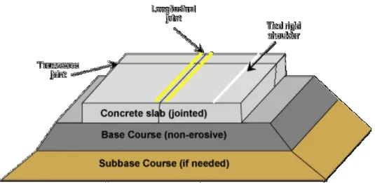
Figure 3.1 - typical section for a flexible pavement 27
Figure 3.2 - typical section for a rigid pavement 27
Figure 3.3 - generalized perpetual pavement design 28
Figure 3.4 - Continuously Reinforced Concrete Pavement 29 Figure 3.5 - Concrete Pavement Contraction Design (CPCD) 29 Figure 3.6 - Jointed Reinforced Concrete Pavement (JRCP) 30 Figure 3.7 - Typical stress distribution under a rigid and a flexible pavement 31
Figure 4.1 - Crack Sealing and Filling differences 33
Figure 4.2 - Pavement Distress Patch 34
Figure 4.3 - Utility Cut Patch 35
Figure 4.4 - Pothole Hazard 35
Figure 5.1 - Cold in-place recycling 38
Figure 5.2 - Hot in-place recycling Train 39
Figure 5.3 - Full depth reclamation process 39
Figure 6.1 - Examples of horizontal alignment components 41
Figure 6.2 - Six track types in curves (Spacek 2000) 42
Figure 6.3 - Curve-System of Forces 42
Figure 6.4 - Minimum Curve Radius and Design Speed (Source: Kramme et Gamham, 1995)
43
Figure 6.5- Accident frequency and curve radius 44
Figure 6.6 - Road Bendiness 45
Figure 6.7 - Irregular Curve Radius 45
Figure 6.8 - Spiral Curves 46
Figure 6.9 - Tuning Radii in Cure Sequences (Source: German Design Guidelines, from Lamm et al.1999)
47 Figure 6.10 - Accident rates and Speed differentials (Source: Anderson et al. (1999)) 48
Figure 6.11 - Friction in Horizontal Curve 49
Figure 6.12 - Jack-knifing 51
Figure 6.13 – Overturning 52
Figure 6.14 - Superelevation in Curve 53
Figure 6.15 - Superelevation Development 54
Figure 6.16 - Lane Widening in a Curve 54
Figure 6.17 - Accident rate in curve and road width (Source: Krebs and Kloeckner (1977))
55
Figure 6.18 - Lateral Clearance in Curve 56
Figure 6.19 - Encroachment Factors (Source: Roadside Design Guide, 2002, by the American association of state highway and transportation officials, Washington, D.C.
Used by Permission)
Figure 6.20 - Smoothing of Side Slopes 57
Figure 6.21 - Examples of Vertical Alignments 59
Figure 6.22 - G, y and K values 59
Figure 6.23 - Downhill warning Sign 61
Figure 6.24 - Brake Check Area 62
Figure 6.25 - Types of Arrester Beds 62
Figure 6.26 - Example of Arrester Bed (Source: Ministère des Transports du Quèbec, 1999)
63 Figure 6.27 - Deceleration Curves (Source: A policy on the geometric design of
highways and streets, 1994, by the American association of state highway and transportation officials, Washington, D.C. Used by permission)
64
Figure 6.28 - Climbing Lane (Source: Transportation Association of Canada, 1999) 65 Figure 6.29 - Combination of intersection and climbing lane at uphill grade to be
avoided in the design
65
Figure 6.30 - Climbing Lane and Traffic Management 66
Figure 6.31 - Examples of K value 66
Figure 6.32 - Sight Distance Restrictions on Sag and Crest Curves 67
Figure 6.33 - Sight Distance and Accident Rate 68
Figure 6.34 - Stopping Sight Distance 69
Figure 6.35 - Maneuvering Sight Distances at an intersection 71 Figure 6.36 - Sight Triangles at a conventional intersection and a roundabout (Right
hand side driving)
73
Figure 6.37 - Passing Manœuvre 74
Figure 6.38 - Meeting Sight Distance 75
Figure 6.39 - Intersection type based on traffic low 78
Figure 6.40 - Number of conflict points at intersections and roundabouts 81 Figure 6.41 - Heavy vehicle encroaching on opposing lane when turning at intersection 82 Figure 6.42 - Hazardous combination: Hill, intersection, accesses, horizontal curve 83
Figure 6.43 - Roundabouts at Urban and Rural Areas 85
Figure 7.1 - Project Location 88
Figure 7.2- Project Overview 89
Figure 7.3 - Project plan 1: Intersection at Via Ronco 90 Figure 7.4 - Project Plan 2: Intersection at Via Lirone 91 Figure 7.5 - Project Plan 3: Intersection at Via Bondanello 91
Figure 7.6 - Road Entrance 92
Figure 7.7 - Balanced Vertical and Horizontal Alignment 94 Figure 7.8 - The Stopping Sight Distance (Source: Decreto Ministeriale 5 Novembre
2011)
98
Figure 8.1 - Flexible Pavement Load Distribution 101
Figure 8.2 - Basic Flexible Pavement Structure 101
Figure 8.3 - Simplified Process of Calculation 104
List of Tables
Table 4.1 - Sealing or Filling Cracks 32
Table 6.1 - Design Quality – Speed Differentials (Lamm et al. in highway design and traffic safety engineering handbook, 1999)
48 Table 6.2 - Design Quality-Friction differentials (Source: Lamm et al. in highway
design and traffic safety engineering handbook, 1999)
50 Table 6.3 - Example showing the Relationship between the Superelevation and Speed 53 Table 6.4 - Accident Reduction (%) Due to Lane or Shoulder Widening (Source: Zegeer et al.1990)
50 Table 6.5 - Stopping Distances-Passenger Cars and Trucks (Source: Transportation
Association of Canada 1999)
53 Table 6.6 - Minimum percentage of Alignment with passing sight distance (Source:
Road Safety Manual 2003)
55
Table 6.7 - Braking Distances in downhill grades 58
Table 6.8 - Sight Distance Criteria at Intersections 60
Table 6.9 - Typical Values of for Stopping Sight Distance Calculation 67 Table 6.10 - Recommended stopping sight distance in several countries (Adapted from:
Harwood et al.1995)
70 Table 6.11 - Maneuvering gaps at intersection (Passenger Vehicle) 70 Table 6.12 - Required Sight Distance (Left turn from minor road) (Source:
Transportation Association of Canada, 1999)
71 Table 6.13 - Comparison of stopping sight distance and decision sight distance (Source: Transportation Association of Canada, 1999)
72 Table 6.14 - Recommended passing sight distances in some countries (Source: Harwood et al. 1995)
73
Table 6.15 - Intersection type based on capacity 74
Table 7.1 - Vertical Alignment Verification 78
Table 7.2 - Design Controls for Sag Vertical Curves 95
Table 7.3 - Design Controls for Crest Vertical Curves 96
Table 7.4 - Horizontal Alignment Verification 97
Table 7.5: Friction Value (Source: Decreto Ministeriale 5 Novembre 2011) 97 Table 8.1 -Results from BISAR 3.0
Table 8.2: BISAR results of the studied points
101 103
1. Introduction
1.1 Preamble:
T
ransportation is necessary for a nation’s growth and development. In fact, it has consumed a considerable portion of human race’s time and resources for as long as it has existed. Several factors should be taken into account in a pavement design, for example the traffic flow, the asphalt mixtures materials and also the environmental factors… which will define, all of them, the pavement performance.Pavement performance is defined as the ability of a pavement to satisfactorily serve traffic over time (AASHTO, 2003). The serviceability is defined as the ability of a pavement to serve the traffic for which it was designed. Integrating both definitions will yield a new understanding of the performance which can be interpreted as the integration of the serviceability over time (Yoder and Witczack, 1975).
Usually it is required a traffic evaluation for both design and rehabilitation. Since the pavement of the new road or that under rehabilitation is usually designed for periods ranging from 10 to 20 years or more, it is to estimate or predict the design loads for this period of time accurately.
A satisfactory pavement has to respect some conditions regarding the asphalt surface that has to exhibit sufficient strength and stiffness, also, adequate sub-base layer strength to provide sufficient bearing capacity to the pavement. Moreover, a stable subgrade and adequate drainage system should be installed to eliminate moisture and avoid base layer instability. Finally a regular maintenance plan should be fixed in order to avoid the pavement deterioration.
1.2Problem Statement:
There are many pavement types all over the world. Each type has its characteristics and performances. The two most popular pavement types are the flexible pavement and the rigid one. All other types derive essentially from these two pavements. However, the pavement field has been innovative. In fact, some pavement types that are produced (Long Life Pavement LLP) and some others which still in test, were made to keep this important domain progressing to answer to new challenges.
Furthermore, a pavement life scale includes all the steps from the construction to the maintenance and recycling part. This latter became a very important field and many researches were made in order to improve pavement’s quality and to save materials.
While designing a road, engineers have to pay attention not only to quotidian users but also to road special users (heavy vehicles and pedestrians). A good design is a design which assures road users comfort and safety. This latter is, obviously, the main goal of any project and still a key point in any research field.
Nowadays, many programs are used to design pavements. BISAR 3.0 is one of the best programs used worldwide. With some required input like the number of layers, the Young’s modulus of the layer and the Poison’s ratio it gives the components of stress, strain and
displacement vector.
While checking the road’s safety, engineers have to check if the stopping sight distance (SSD) is less than the sight distance (SD) of the same curve or not. If yes, so the curve is safe and vehicles can pass safely. But if the stopping sight distance is greater than the sight distance, either the design speed or the curve radius has to be changed, depending on the case. Some exceptions are permitted when the curve is so short and there are no obstacles in the right hand curves.
1.3 Objectives of the thesis:
This thesis aims to:1- Study the different types of pavements.
2- Introduce the pavement maintenance and its different categories. 3- Illustrate the pavement recycling and its different methods.
4- Make the alignment design (Horizontal alignment and vertical alignment) of a new rural road in the province of Bologna.
5- Design a pavement of a new rural road in the province of Bologna using the program BISAR 3.0.
1.4 Methodology:
The informations in this thesis were gathered from different sources: in order to study the different types of pavements and the characteristics of each one, several publications and articles were used. Other articles and books helped to understand the pavement maintenance procedure and also the pavement recycling. The AASHTO, TAC and the PIARC books were used to study the technical sheets, and other official reports helped to get informations about the project site and its characteristics. All the statistics and data used in this thesis were gathered from the official web pages.
1.5 Thesis Layout:
This thesis contains nine chapters. Chapter 1 is an introductory chapter outlining the problem statement and the objectives of the thesis.
Chapter 2 provides a literature review. It presents a simple description of the rigid and the
flexible pavement, which are the most important types of pavement from where derive all types of pavements.
Chapter 3 describes in detail the different types of pavements and the characteristics of each
one. In particular it describes the flexible and the rigid pavement as all the other types of pavements derive from these two types.
Chapter 4 presents a detailed description of the pavement maintenance. The first part
describes the preventive maintenance with its different treatments, and the second part explains the structural maintenance procedure and gives some solutions in order to mitigate the pavement deterioration.
Chapter 5 illustrates the different pavement recycling procedures. It takes the hot/cold in
place recycling, the full depth reclamation and the hot mix recycling and describes the materials used in each procedure. Moreover, it shows the main advantages of these four procedures considering the pavement recycling as a part of the pavement’s life.
Chapter 6 describes the alignment design concept and takes the main technical sheets used in
the design part. In fact, it presents the horizontal alignment which comprises straight lines, circular curves and spiral curves which together can make various sequences. Moreover, it illustrates the vertical alignment which consists of straight segments connected by sag or crest vertical curves. Furthermore, it explains the sight distance concept and the precautions to be taken for a safe passing of a vehicle without hitting any object on his path. In the last part, it describes the intersections which represent an essential part of a road network, besides it gives the main factors, which depends on, the choice of the intersection type. Finally, it discusses the safety at intersections and gives some examples.
Chapter 7 describes the alignment design of a new rural road in the province of Bologna.
Indeed, it presents the results of the vertical and horizontal alignment of the road. Also, it illustrates the main methods and formulas used in the design previously presented.
Chapter 8 describes the pavement design of a new rural road in the province of Bologna
using the BISAR 3.0 program, which calculates the stresses, strains and displacements in an elastic multi-layer system. For this, it requires some input like the number of layers and its thickness (except the semi-infinite base layer), the young’s modulus of each layer, the number of loads, the co-ordinates of the position of the center of the loads and the coordinates of the position of which output is required. In the last part, it gives some results about the pavement design (stress, strain and displacement) and some interpretations. Moreover, it studies the fatigue life of the road and gives some interpretations and recommendations.
Chapter 9 summarizes the conclusions taken from this thesis and presents recommendations
2. Literature Review:
2.1 Introduction:
R
oad pavements are divided into two main categories: Rigid and Flexible. The wearing surface of a rigid pavement is usually constructed of Portland cement concrete such that it acts like a beam over any irregularities in the underlying supporting material. The wearing surface of flexible pavements, on the other hand, is usually constructed of bituminous materials such that they remain in contact with the underlying material even when minor irregularities occur (Traffic and highway engineering, Nicholas J. Garber and Lester A. Hoel 1999).Generally, flexible pavements are constructed of a bituminous surface underlaid with a layer of granular material and a layer of fine materials. However, rigid pavements consist of Portland cement concrete and may or may not have a base course between the subgrade and the concrete surface.
2.2 Structural components of a flexible pavement:
Flexible pavements consist of a subgrade (prepared roadbed), the sub-base, the base and the wearing surface. This latter, when made of Hot Mix Asphalt becomes stiffer and contribute more to the pavement strength.
Figure 2.1: Schematic of a Flexible Pavement
→The performance of the pavement depends on the satisfactory performance of each
component.2.2.1 Subgrade:
The subgrade is the natural material located along the horizontal alignment of the pavement (It serves as the foundation of the pavement structure). Depending on the type of pavement
being constructed, it is necessary to treat the subgrade material to achieve the required the strength properties.
2.2.2 Sub-base course:
Located immediately above the subgrade, the sub-base component consists of material of a superior quality to that which generally is used for subgrade construction. When the quality of the subgrade material meets the requirements of the sub-base material, the sub-base component may be omitted (Traffic and highway engineering, Nicholas J. Garber and Lester A. Hoel 1999).
→
When the sub-base material does not correspond to the requirements, a process of treating soils to improve their engineering properties known as stabilization can be used. In fact, the available material should be treated with other materials to achieve the necessary properties.2.2.3 Base course:
The base course is placed above the sub-base (above the subgrade if the sub-base course is not used). It consists of granular materials such as sand, crushed stone, crushed or uncrushed gravel and crushed or uncrushed slag.
Usually, the base course materials include stricter requirements than those for sub-base course. In some cases, to increase the stiffness characteristics of heavy-duty pavements, the base course can be treated with asphalt or Portland cement.
2.2.4 Surface course:
The surface course is the upper layer of the pavement section located immediately above the base course. The surface course in flexible pavements consists generally of a mixture of mineral aggregates and asphaltic materials. It must be able to withstand a wide variety of factors that can accelerate the deterioration process of the pavement.
2.3 Flexible Pavement Distress and Performance:
2.3.1 Flexible Pavement Distress:
The most commonly distresses on flexible pavement surfaces include cracking, rutting, pothole, and surface deterioration. In this section, various pavement distresses classes are briefly discussed according to the definitions from the US Department of Transportation distress identification manual (Federal Highway Administration, 2003) and the LTTP Distress Identification Manual.
2.3.1.1 Fatigue Cracking:
Fatigue (also called alligator) cracking, which is caused by fatigue damage, is the principal structural distress which occurs in asphalt pavements with granular and weakly stabilized bases. Alligator cracking first appears as parallel longitudinal cracks in the wheel paths, and progresses into a network of interconnecting cracks resembling chicken wire or the skin of an alligator. Alligator cracking may progress further, particularly in areas where the support is weakest, to localized failures and potholes.
Fig 2.2: Fatigue (alligator) cracking in Flexible Pavement
Factors which influence the development of alligator cracking are:
●The number and magnitude of applied loads;
●The structural design of the pavement (layer materials and thicknesses); ●The quality and uniformity of foundation support;
●The asphalt content.
2.3.1.2 Block Cracking and Transverse (Thermal):
Block cracking is the cracking of an asphalt pavement into rectangular pieces ranging from approximately 30 cm to 300 cm on a side. Block cracking occurs over large paved areas such as parking lots, as well as roadways, primarily in areas not subjected to traffic loads, but sometimes also in loaded areas. Thermal cracks typically develop transversely across the traffic lanes of a roadway.
Figure 2.3: Longitudinal Cracking (Medium Severity)
Block cracking and thermal cracking are both related to the use of asphalt which is or has become too stiff for the climate. Both types of cracking are caused by shrinkage of the asphalt in response to low temperatures, and progress from the surface of the pavement downward. The key to minimizing block and thermal cracking is using an asphalt of sufficiently low stiffness (high penetration).
2.3.1.3 Potholes:
A pothole is a bowl-shaped hole through one or more layers of the asphalt pavement structure, between about 15 and 90 centimeters in diameter. Potholes begin to form when fragments of asphalt are displaced by traffic wheels, e.g., in alligator-cracked areas. Potholes grow in size and depth as water accumulates in the hole and penetrates into the base and subgrade, weakening support in the vicinity of the pothole.
2.3.1.4 Rutting:
Rutting is the formation of longitudinal depression of the wheel paths, most often due to consolidation or movement of material in either the base or subgrade or in the asphalt layer. Another, unrelated, cause of rutting is abrasion due to studded tires and tire chains. Deformation which occurs in the base and underlying layers is related to the thickness of the asphalt surface, the thickness and stability of the base and sub-base layers, and the quality and uniformity of subgrade support, as well as the number and magnitude of applied loads.
Figure 2.5: Rutting
2.3.1.5 Longitudinal Cracking:
Non-wheel path longitudinal cracking in an asphalt pavement may reflect up from the edges of an underlying old pavement or from edges and cracks in a stabilized base, or may be due to poor compaction at the edges of longitudinal paving lanes. Longitudinal cracking may also be produced in the wheel paths by the application of heavy loads or high tire pressures.
2.3.2 Stress Distribution:
Stress distribution in a road structure is studied in order to know how phenomena develop in the road structure and in particular to determine the behavior of the asphalt layers. Figure 2.7 shows a wheel load applying a downward pressure on a road surface. The load is spread out and reduced in intensity by the various pavement layers. The pressure, P1, on the subgrade is much less than the tire pressure, P0, on the pavement surface. Consequently, higher quality – and generally more expensive – materials are used in the more highly stressed upper layers of all pavement systems, and lower quality and less expensive materials are used for the deeper layers of the pavement. However, if this condition is not met or if the deterioration of these layers occurs, the durability of the pavement is significantly reduced. This may result in the onset of premature pavement distress, in the form of fissures, longitudinal cracks, alligator cracks, surface depreciations or potholes.
Figure 2.7: Spread of wheel load pressure through the pavement structure
The vertical forces are due to the weight applied on the wheel, the horizontal shear stresses, occurring on the pavement surface during accelerating and breaking phases are due to the adherence between tires and wear course during rolling. The upper layers are subjected to bending stresses while the lower layers are subjected to vertical forces, mainly compression. Numerous studies undertaken in recent years have revealed that, indeed, stress distribution is very complex because the tensile progress does not only affect surfaces layers, but also the layers immediately below (Muraya, 2007).
It is possible to represent the state of compression and tension (Figure 2.8 below): The load applied by a tire can be illustrated with a concentrated force that determines a compression zone, immediately below, and two traction areas in the adjacent sides.
Figure 2.8: Pavement Deflection under Load
If the deflection is large enough and occurs enough times, the tension stress can cause a fatigue crack at the bottom of the layer. Additional loads cause this crack to migrate upward until it reaches the surface. Surface water can then penetrate through the crack into the base and weaken it. This causes larger deflections in the adjacent pavement and more cracks until pavement failure (alligator cracking) occurs.
3. Pavement Analysis:
3.1 Introduction:
G
enerally, Pavements are divided into two main categories: Rigid and Flexible. The wearing surface of rigid pavements is usually constructed of Portland cement concrete such that it acts like a beam over any irregularities in the underlying supporting material. The wearing surface of flexible pavements, on the other hand, is usually constructed of bituminous materials such that they remain in contact with the underlying material even when minor irregularities occur. Flexible pavements usually consist of a bituminous surface underlaid with a layer of granular material and a layer of a suitable mixture of coarse and fine materials. Traffic loads are transferred by the wearing surface to the underlying supporting materials through the interlocking of aggregates, the frictional effect of the granular materials and the cohesion of the fine materials.Flexible pavements are further divided into three subgroups: High type, intermediate type and low type. High type pavements have wearing surfaces that adequately support the expected traffic load without visible distress due to fatigue and are not susceptible to weather conditions. Intermediate type pavements have wearing surface that range from surface treated to those with qualities just below that of high type pavements. Low type pavements are used mainly for low cost roads and have wearing surfaces that range from untreated to loose natural materials to surface-treated earth. (Traffic and highway engineering, 1999).
3.2 Types of Pavements:
There are several kinds of pavement there can be used for multiple purposes. It often happens that some pavements can be used for more than one type of vehicle/transportation or load, but often only few are suitable for the purpose they are designed for.
3.2.1 Flexible Pavement:
A flexible pavement structure is typically composed of several layers of material with better quality materials on top where the intensity of stress from traffic loads is high and lower quality materials at the bottom where the stress intensity is low. Flexible pavements can be analyzed as a multi-layer system under loading. A typical flexible pavement structure consists of the surface course and underlying base and sub base courses. Each of these layers contributes to structural support and drainage. When hot mix asphalt (HMA) is used as the surface course, it is the stiffest and may contribute the most to pavement strength, which is depending on the thickness. The underlying layers are less stiff, but are still important to pavement strength as well as drainage and frost protection.
Figure 3.1 shows a typical section for a flexible pavement.
Figure 3.1: Typical section for a flexible pavement
3.2.2 Rigid Pavement:
A rigid pavement structure is composed of a hydraulic cement concrete surface course and underlying base and sub base courses (if used). Another term commonly used is Portland cement concrete (PCC) pavement, although with today’s pozzolanic additives, cements may no longer be technically classified as “Portland”. The surface course is the stiffest layer and provides the majority of strength. The base or sub base layers are orders of magnitude less stiff than the PCC surface but still make important contributions to pavement drainage and frost protection and provide a working platform for construction equipment.
Rigid pavements are substantially ‘stiffer’ than flexible pavements due to the high modulus of elasticity of the PCC material, resulting in very low deflections under loading. The rigid pavements can be analyzed by the plate theory. Rigid pavements can have reinforcing steel, which is generally used to handle thermal stresses to reduce or eliminate joints and maintain tight crack widths.
Figure 3.2 shows a typical section for a rigid pavement.
3.2.3 Composite Pavement:
A composite pavement is composed of both hot mix asphalt (HMA) and hydraulic cement concrete. Typically, composite pavements are asphalt overlays on top of concrete pavements. The HMA overlay may have been placed as the final stage of initial construction, or as part of a rehabilitation or safety treatment. Composite pavement behavior under traffic loading is essentially the same as rigid pavement.
3.2.4 Perpetual Pavement:
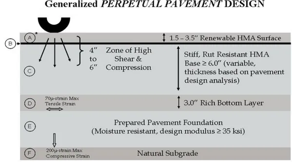
Perpetual pavement is a term used to describe a long-life structural design. It uses premium HMA mixtures, appropriate construction techniques and occasional maintenance to renew the surface. Proper construction techniques need to be kept in mind to avoid problems with permeability, trapping moisture, segregation with depth, and variability of density with depth. A perpetual pavement can last 30 yr. or more if properly maintained.
Structural deterioration typically occurs due to either classical bottom-up fatigue cracking, rutting of the HMA layers, or rutting of the subgrade. Perpetual pavement is designed to withstand almost infinite number of axle loads without structural deterioration by limiting the level of load-induced strain at the bottom of the HMA layers and top of the subgrade and using deformation resistant HMA mixtures.
Figure 3.3 shows a generalized perpetual pavement design.
3.2.5 Continuously Reinforced Concrete Pavement:
CRCP provides joint-free design. The formation of transverse cracks at relatively close intervals is a distinctive characteristic of CRCP. These cracks are held tightly by the reinforcement and should be of no concern as long as the cracks are uniformly spaced, do not spall excessively, and a uniform non-erosive base is provided.
Figure 3.4 shows a typical section of CRCP.
Figure 3.4: Continuously Reinforced Concrete Pavement.
3.2.6 Concrete Pavement Contraction Design (CPCD):
CPCD uses contraction joints to control cracking and does not use any reinforcing steel. An alternative designation used by the industry is jointed concrete pavement (JCP). Transverse joint spacing is selected such that temperature and moisture stresses do not produce intermediate cracking between joints. Dowel bars are typically used at transverse joints to assist in load transfer. Tie bars are typically used at longitudinal joints.
Figure 3.5 shows a typical section of CPCD.
3.2.7 Jointed Reinforced Concrete Pavement (JRCP):
JRCP uses contraction joints and reinforcing steel to control cracking. Transverse joint spacing is longer than that for concrete pavement contraction design. (CPCD) This rigid pavement design option is no longer endorsed by the department because of past difficulties in selecting effective rehabilitation strategies. However, there are several remaining sections in service.
Figure 3.6 shows a typical section of jointed reinforced concrete pavement.
Figure 3.6: Jointed Reinforced Concrete Pavement (JRCP)
3.2.8 Post-tensioned Concrete Pavement:
Post-tensioned concrete pavements remain in the experimental stage and their design is primarily based on experience and engineering judgment. Post-tensioned concrete has been used more frequently for airport pavements than for highway pavements because the difference in thickness results in greater savings for airport pavements than for highway pavements.
3.3 Rigid and flexible pavement characteristics:
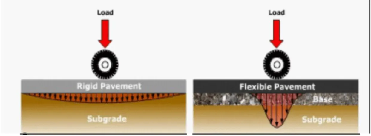
The primary structural difference between a rigid and flexible pavement is the manner in which each type of pavement distributes traffic loads over the subgrade. A rigid pavement has a very high stiffness and distributes loads over a relatively wide area of subgrade – a major portion of the structural capacity is contributed by the slab itself.
The load carrying capacity of a true flexible pavement is derived from the load-distributing characteristics of a layered system.
Figure 3.7 shows load distribution for a typical flexible pavement and a typical rigid pavement.
Figure 3.7: Typical stress distribution under a rigid and a flexible pavement.
4. Pavement Maintenance:
4.1 Introduction:
A
n asphalt pavement, when designed and constructed properly, will provide years of service. All pavements will eventually require some type of maintenance. Thus, maintenance is an essential practice in providing for the long-term performance and the esthetic appearance of an asphalt pavement.The purpose of pavement maintenance is to correct deficiencies caused by distresses and to protect the pavement from further damage. Moreover, various degrees or levels of maintenance can be applied to all pavements, regardless of the end use. Pavement maintenance is either preventive or corrective. Preventive maintenance is the procedure performed to protect the pavement and decrease the rate of deterioration of the pavement quality. Corrective maintenance is the procedure performed to correct a specific pavement failure or area of distresses. Some procedures will address both functions (Roberts et al. 1991). The sealing of cracks for the most part is considered a preventive maintenance measure. Patching is considered a corrective maintenance measure.
Pavement maintenance can be described by two different categories:
●Preventive maintenance: Activities that prevent or reduce further damage to the pavement ●Structural maintenance: Activities that repair or improve the structural integrity of the pavement (Very expensive).
4.2 Preventive Maintenance:
Preventive maintenance activities include: ● Pavement sealers or sealcoats
● Crack filling and sealing ● Surface Treatments
4.2.1 Pavement sealers or sealcoats:
Pavement sealers are used to restore or rejuvenate an oxidized asphalt pavement surface. They are also used to fill hairline cracks that are less than 3 mm wide.
Some sealers provide an improved or ‘new’ appearance to an aged asphalt pavement and can protect the asphalt pavement from fuel or oil damage.
The most common pavement sealers are: - Fog seals
- Asphalt emulsion seal coat - Coal tar seal coat
4.2.2 Crack filling and sealing:
The most common and widely used maintenance activity for pavements, regardless of use, is crack sealing or filling. Crack sealing and filling is an inexpensive maintenance procedure that will significantly delay further deterioration of the pavement.
Cracks less than 3 mm wide are too narrow to be sealed or filled. A pavement sealer or surface treatment is adequate to treat these narrow cracks. Cracks that are 3-25 mm can be sealed or filled with an application of a crack sealant or filling material. However, cracks that are greater than 25 mm wide are generally too wide to be sealed or filled and should be repaired through the use of a patching mixture or they should be cut out and replaced with a full depth patch.
Crack sealing and crack filling are actually two separate procedures:
- “Crack sealing” is the installation of a specially formulated crack sealing material either above or into working cracks using unique configurations to prevent the intrusion of water into the crack.
- “Crack filling” is the placement of crack filling material into non-working cracks to substantially reduce the intrusion of water into the wrack.
Figure 4.1: Crack Sealing and Filling differences
→The significant differences are that crack sealing is applied to working cracks and
crack filling is applied to non-working cracks. Moreover, crack sealing involves placing sealing material in or on top of the crack, but crack filling involves placing filling material in the crack.4.2.3 Surface treatments:
Surface treatment is a broad category, encompassing several types of asphalt and coal tar sealers or asphalts aggregate combinations. An asphalt surface treatment consists of a thin layer of asphalt concrete formed by the application of an asphalt emulsion, cutback or asphalt binder plus aggregate to protect or restore an existing pavement surface.
The surface treatment will perform one or more of the following functions: - Provide a weather resistant surface.
- Provide a fuel or oil resistant surface.
- Provide an esthetically pleasing coating to the pavement surface. - Fill or seal hairline or cracks under 3 mm width.
- Fill distortions or rutting. - Provide a skid resistant surface.
→
One function that a surface treatment will not provide is structural strength. The luck of any significant aggregate interlock and thickness in a surface treatment results in no structural strength and is not considered when determining the overall required thickness for an asphalt pavement.4.3 Structural Maintenance:
Structural maintenance activities include: ●Patching
●Pothole filling
●Overlays (Resurfacing) ●Reconstruction
4.3.1 Patching:
The patching of a pavement is a permanent solution to pavement distresses, usually high severity distresses. The purpose of patching is essentially, permanently repairing the portion of the pavement that is defective due to:
- Pavement distress, such an alligator cracking, severe transverse cracking, severe block cracking, etc.
Figure 4.3: Utility Cut Patch
4.3.2 Pothole filling:
Pothole filling is a somewhat temporary measure, which can also be considered patching. The purpose of this method is to temporarily eliminate the pothole as a road hazard and nuisance. Potholes are the result of a rapid disintegration portion of the pavement that was not repaired in time.
Potholes can occur on any type of asphalt pavement, including local roads, parking lots, and freeways. Pothole filling can be part of a routine maintenance program or it may be performed as an emergency repair. Potholes can be a hazard to vehicles and pedestrians.
Potholes generally become more apparent under harsh weather conditions, such as freezing or very wet weather. Thus, emergency pothole filling usually occurs during inclement weather. Pothole filling is a very simple process. There are four recognized procedures for pothole filling:
- Throw and go - Throw and roll - Semi permanent - Injection
4.3.3 Overlays (Resurfacing):
In more severe cases of asphalt failure, a long-term and cost-effective solution is to resurface the asphalt pavement. If there is a grade depression (standing water on the pavement) and/or large sections of alligatored areas (interconnecting cracks forming a series of blocks resembling an alligator's skin), it is a good idea to have the pavement resurfaced. This process consists of several steps; In fact, after preparation and cleaning of the area, tack coat will be applied. Hot asphalt will then be installed to the approximate specified depth and compacted with a multi-ton vibratory roller to guarantee proper compaction.
*Resurfacing options:
a) Geotextile Reinforced Resurfacing: An option that may be included with asphalt resurfacing is Petromat. Petromat is a non-woven, petroleum-based geotextile fabric used to retard reflective cracking between the existing pavement and the newly installed asphalt surface. This fabric acts as a waterproofing membrane, while also adding structural support and strength.
b) Leveling Binder: In low areas, hot asphalt is installed at various depths to adjust pitch to proper grades.
c) Butt/Joint grinding: In areas requiring the resurface to tie into other existing surfaces (i.e., concrete, etc.) asphalt is removed along the perimeter to allow proper depth of asphalt on the edge.
d) Transitional milling: In areas requiring the resurface to tie into other existing surfaces (i.e., concrete, etc.), asphalt will be milled and replaced to allow proper depth and transitions. An asphalt milling machine is used to remove an appropriate depth of pavement in a grinding process. The spoils can then be hauled off and recycled.
4.3.4 Reconstruction:
As asphalt pavement progresses through its performance lifecycle, its appearance diminishes over time. Fine hairline cracks spread and deepen within the asphalt. Without ongoing maintenance, water may enter through cracks and holes may form, undermining the substrate. In this case, the most effective form of repair is to remove and replace the deteriorated area. This process consists of several important steps to ensure that the repair is performed properly: Area(s) will be milled and the existing deteriorated asphalt will be removed to the approximate specified depth. Existing stone base will be compacted and tack coat will be applied to perimeter of patches to guarantee proper bonding. Hot asphalt will be installed and compacted with a multi-ton vibratory roller and/or vibratory plate.
→ the cost for asphalt removal & replacement depends upon the geographic location, the amount of grading and substrate work required, and other site-specific factors.
5. Pavement Recycling:
5.1 Introduction:
T
he use of recycled materials in asphalts pavements has been occurring with varying degrees of success for the past 20 years. RAP reclaimed concrete pavement, coal fly ash, and the blast furnace slags are the most common materials that are recycled back into an asphalt pavement (United States Department of Transportation USDOT 2000).Asphalt pavement recycling is the recycling or reusing an existing asphalt pavement into a new and structurally sound asphalt pavement. There are four common methods used in asphalt pavement recycling:
●Cold in-place recycling ●Hot in-place recycling ●Full Depth Reclamation ●Hot Mix Recycling
5.2 Cold in-place recycling:
Cold in-place recycling involves the recycling of existing asphalt pavement in situ without the use of heat. An asphalt emulsion is typically used as recycling agent. The process includes pulverizing or tilling the existing pavement, the application of the recycling agent, placement and compaction.
The use of a recycling train is often used for large or long roadway projects. The recycling train consists of pulverizing, screening, crushing and mixing units. The processed roadway is deposited in a window from the mixing machine, where it is then picked up, placed and compacted with conventional HMA paving equipment.
Figure 5.1: Cold in-place recycling
→Advantages of cold in-place recycling include significant remedial corrections of most
pavement distresses, environmentally friendly, and the complete reuse of the existing pavement.5.3 Hot in-place recycling:
Hot in-place recycling involves heating and softening the existing asphalt pavement and then scarifying it. A recycling agent, usually an asphalt emulsion, is added to the sacrificed RAP. Sometimes, a new asphalt mixture is also added to the RAP. The depth of recycling can vary from 20 to 50 mm.
Hot in-place recycling can be performed in either a single pass or a multiple pass operation. In a single pass operation, the sacrificed RAP is combined with a new asphalt mixture if desired, and then compacted. In a multiple pass operation, the RAP and recycling agent is compacted first and then a new wearing course is added.
Figure 5.2: Hot in-place recycling Train
→
The advantages of hot in-place recycling are that pavement distresses, including surface cracks can be corrected and the existing oxidized asphalt binder can be rejuvenated.5.4 Full depth reclamation:
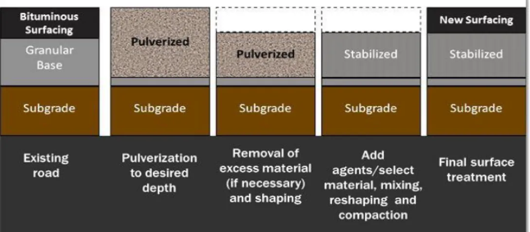
Full in depth reclamation is where the entire asphalt pavement and a predetermined amount of the underlying base course are treated to produce a stabilized base course. The existing asphalt pavement course becomes part of the new pavement’s base course. Full depth reclamation is a cold mix recycling process using asphalt emulsions, calcium chloride, fly ash and possibly other additives to stabilize the base course.
The process consists of pavement pulverization, mixing with the additives, compaction, and the construction of a wearing course. If the existing pavement material is not adequate to provide the desired thickness of stabilized base, new aggregates may be added. Full depth reclamation is typically performed to depths of 100-300 mm.
Figure 5.3: Full depth reclamation process
→
This method has an advantage that it can remove most of the pavement distresses and upgrade its structural strength.5.5 Hot mix recycling:
Hot mix recycling involves removing or milling up the existing asphalt pavement, crushing it if necessary, and adding it to HMA at mixing plant. RAP can be added at both batch mixing and drum plants. The HMA containing RAP is constructed using the same methods for conventional asphalt mixtures (United States Department of Transportation USDOT 1997). The most common method of pavement recycling is the hot mix recycling method. The use of hot mix recycling is prevalent to geographical areas with some areas using RAP in all the HMA being produced and some areas with no RAP usage at all. The availability of RAP and landfills usually determine how many tones of HMA being produced contain RAP. Urban areas generally see more RAP usage than rural areas.
During the milling or crushing process of the existing asphalt pavement, a significant amount of fine material can be generated, which can limit the amount of RAP used in the new asphalt mixture. The heating of the RAP in the mixing plant extracts most of the asphalt binder from it and allows it to be blended throughout the new asphalt mixture. The ability of the mixing plant to transfer enough heat to dry the RAP and extract the asphalt binder from it limits the total amount of RAP that can be incorporated in the HMA.
Some modern drum mixing plants, such as double drum plants, have been designed to incorporate up to 70 percent RAP or more, but typically the maximum is 50 percent. Batch mixing plants can usually only incorporate up to 30 percent RAP in the HMA.
6. Technical Sheets: Alignment Design Concept
6.1 Horizontal Alignment:
6.1.1 General Principles:
G
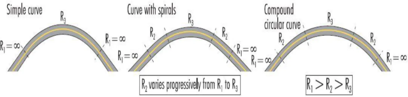
enerally, the horizontal alignment of a road may comprise straight lines, circular curves (with a constant radius), and spiral curves, whose radius changes regularly to allow for a gradual transfer between adjacent road segments with different curve radii. Various sequences of these three components are possible.Figure 6.1 shows three types of common sequences: Simple curve, curve with spiral(s), and curves made up of several decreasing radii.
Figure 6.1: Examples of horizontal alignment components
● Accidents: Several studies have shown that the accident risk in curves is so much high. It can be concluded that:
-The accident rate in curves is 1.5 to 4 times higher than in tangents (Zegeer et al, 1992) -The severity of accidents in curves is high (Glennon et al, 1986). From 25% to 30% of fatal accidents occur in curves (Lamm et al, 1999).
-Approximately 60% of all accidents to occur in horizontal curves are single-vehicle off-road accidents (Lamm et al, 1999).
-The proportion of accidents on wet surfaces is high in horizontal curves.
-Accidents occur primarily at both ends of curves. Council (1998) notes that in 62% of fatalities and 49% of other accidents occurring in curves, the first manoeuvre that led to the accident was made at the beginning or the end of the curve.
→Thus, there is a relative relationship between the speed reduction in the curve and the probability of accident: When the required speed reduction in the curve is high, the probability of error and accident becomes also so high (encroachment, skidding, run-off- the road, etc.). Moreover, the risk is even higher when the speed reduction is unexpected or unusual (isolated sharp curve).
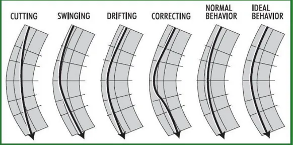
Spacek (2000) tried to describe the behavior of drivers in curves by six track types (Figure 6.2). The correcting crack type which is due to an underestimation of the curve features locally reduces the radius followed by the car and increases the risk of accident. Improvements of sight distance, curve conspicuity and warning devices may reduce this type of problem.
Figure 6.2: Six track types in curves
● Potential Solutions: Lengthening the radius of a curve is a solution that is often considered to reduce accidents in sharp horizontal curves. However, costs can be very high and the economic effectiveness of the measures needs to be properly assessed.
Other potential solutions include:
-Improving warning and guidance provided for drivers: better sight distance, curve conspicuity, signing and marking, delineation.
-Minor geometric improvements, including modifications to the shoulder and roadside conditions.
6.1.2 Curve Radius (or Degree of Curve):
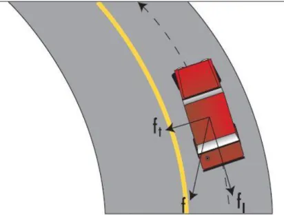
From a stability point of vue, vehicle travelling in a curve is always pushed toward the exterior side of the road by the centrifugal force. This latter is counteracted by transverse friction (between the tires and the road) and the superelevation force (Figure 6.3).
Figure 6.3: Curve-System of Forces
The higher is the vehicle speed, the bigger is the magnitude of the centrifugal force until reaching a point where this force is equal to the sum of these counteracting forces and skidding occurs:
Fc = Fe + Ft (Equation 1)
Where: Fc = Centrifugal Force Fe = Superelevation Force Ft = Transverse Elevation Force
→However, some vehicles having a high center of gravity may overturn before skidding.
By Transforming equation 1, one can derive the basic equation that is used to calculate the minimum curve radius, based on speed, friction and superelevation values.(Equation 2)
Where: Rmin = Minimum Curve Radius (m) V = Speed (Km/h)
e = Superelevation (m/m) Ft = Coefficient of Transverse Friction
The minimum curve radii values used at the design stage range from about 100m for a design speed of 50 Km/h to about 500m for a design speed of 100 Km/h ( Figure 6.4).
Figure 6.4: Minimum Curve Radius and Design Speed (Source: Kramme et Garnham, 1995)
Such radius values may be calculated with equation 2, using low coefficients of transverse friction, in order to:
-Take into account difficult drive conditions ( wet pavement and worn tires). -Avoid substantial increases in curve breaking distances.
-Provide vehicle occupants with an acceptable level of comfort.
●Safety: On rural roads, accident frequencies are generally seen to increase as curve radii
decrease. A convex downward relationship is often found as shown if figure 6.5 below.
Figure 6.5: Accident frequency and curve radius
→The increase of accidents is significant when the radius is less than 400m.
However, the accident frequency in a curve is not influenced only by the characteristics of the curve itslef (radius, deflection angle, friction, superelevation, etc.) but also by the characteristics of the road alignment prior to the curve (length of tangent prior to the curve and general bendiness of the road).
It is, therefore, not surprising for two similar curves to have different safety performance depending on the road context in which they are located.
●General Bendiness1: The general bendiness of a road has a direct effect on the drivers level
of attention and expectation with respect to the forthcoming road alignment. A sharp curve is more hazardous on a fairly straight road than a winding one. Figure 6.6 shows how to calculate Bendiness:
Figure 6.6: Road Bendiness
●Irregular Curve Radius: Marked changes in radius in a curve are to be avoided since they
may surprise drivers and increase the risk of error. The accident risk is higher when a small curve follows a larger one. Yerpez and Fernandez (1986) found that 50% reduction of curve over a distance of more than 30m increases the number of accidents. An irregular radius can be converted into a uniform circular radius or clothoid or a combination of both without a major changes in road alignment.
Figure 6.7: Irregular Curve Radius
●Spiral Curve: Spiral curves (also called transition curves or clothoids) are the third element
in a horizontal alignment, along with tangent and circular curves. According to Lamm et al. (1999), spiral curves:
-Improve driving comfort by allowing a natural increase and decrease in centrifugal force as a vehicle enters and leaves a circular curve.
-Minimize encroachments and increase speed uniformity. -Facilitate water runoffs in the superelevation transition zone.
-Enhance the appearances of the highway by eliminating noticeable breaks at the beginning and end of circular curves.
Spiral Curves are calculated using this formula:
(Equation 3)
Where: R = Curve Radius (at distance L) (m) A = Parameter of the Spiral Curve (m)
Ls =Distance traveled from the starting point of the Curve (m) Figure 13 shows the resulting curves for A= 150m and A= 300m
Figure 6.8: Spiral Curves
Overly long spiral curves should be avoided as they can hinder the visual perception of the curve and may contribute to drainage problems.
According to Council (1998), a spiral curve reduces accident rates by 8% to 25% on roads with high design standards. However, safety improvements brought about by transition curves are less evident on roads with lower geometric standards.
Other studies report contradictory results, which probably led Lamm et al. (1999) to conclude that:
« Generally, speaking with respect to safety effects, the application of clothoids should not be
overemphasized in the design process as it has been done so far in several countries. Of course, one should not forget the importance of other design impacts that transition curves
6.1.3 Speed Differentials:
Operating speed is influenced by several factors related to the driver, road and road side conditions, vehicle characteristics, traffic conditions and weather conditions. Road alignment is undoubtedly the most important factor among road characteristics that influence driver’s speed.
Speed variations along a road have direct impact on road safety. High standard roads should be designed to allow drivers to travel safely at a relatively constant speed that meets their needs and expectations. Otherwise driving errors are likely to occur.
In the early seventies, German researchers developed rules to help designers choose horizontal alignment sequences that would reduce operating speed variations along a route. The method known as Relation Design is seen as a major improvement over traditional design methods that merely checked compliance with minimum radii values.
Figure 6.9: Tuning Radii in Cure Sequences (Source: German Design Guidelines, from Lamm et al.1999)
Relation design rules can also be expressed in terms of speed differentials. Lamm et al. (1999) recommend that a road’s design quality can be assessed by comparing the 85th
percentile speed of passenger cars (V85) on two successive road segments. If the differential is less than 10 km/h, the design is deemed good; between 10 km/h and 20 km/h, acceptable; over 20 km/h, poor. Spain uses similar criterion, but based on the 99th percentile speed (V99).
Table 6.1 below shows a small comparison between Lamm et al (1999) and Spain:
Table 6.1: Design Quality – Speed Differentials (Source: Lamm et al. in highway design and traffic safety engineering handbook, 1999)
●Safety: Anderson et al. (1999) analyzed the impact of operating speed differentials (
V85) on
accidents. Based on data collected at 5287 curves, that found that accident rate in curves with speed differential of over 20 km/h is two times higher than in those with a speed differential of 10 km/h to 20 km/h and six times higher than in those with a speed differential of less than 10 km/h (Figure 6.10).6.1.4 Surface Condition:
The available transverse friction in a curve has a strong impact on the maximum speed on which it can be driven. For example, for a curve with a radius of 300m, a superelevation of 0.06 and a coefficient of transverse friction (ft) of 0.30, the maximum (theoretical) speed is 108 km/h. With aft of 0.80 it raises to 148 km/h. Transverse friction values used at the design stage (ftd) are generally much lower than transverse friction values that are available on roads. The choice of ftd values is based on the following objectives:
-Providing a safety margin for adverse weather conditions.
-Avoiding excessive increase in breaking distances in curves (Figure 6.11). -Offering a comfortable ride to vehicles occupants.
Figure 6.11: Friction in Horizontal Curve
f² = fl² + ft² (Equation 4)
Where: f =Coefficient of Friction (total) fl =Coefficient of Longitudinal Friction Ft =Coefficient of Transverse Friction
→When braking in a curve, the total available friction is distributed between its longitudinal
component (fl), required for braking, and its transverse component (ft), required for changes in direction. To avoid excessive increases in braking distances, ftd values not greater than 40% to 50% of the total friction expected under difficult conditions are selected, so that around 90% of the total friction remains available for braking manoeuvres.As a result, horizontal curves can often be driven faster than design and posted speeds (under favorable conditions). Realizing this, a number of drivers adopt relatively high speeds, thereby reducing their safety margin. It is a driving habit that may prove to be hazardous if the skid resistance at a specific curve low and the driver does not decelerate sufficiently. When the friction available in the curve becomes lower than the required friction, the driver loses the control of his vehicle. The required friction (fr) can be calculated with the following equation:
– (Equation 5)
Where: R= Curve Radius
V85= Speed (km/h)
e= Superelevation (m/m) fr= Friction Required at V85
Lamm et al. (1999) recommend assessing the quality of a horizontal alignment by comparing the coefficient of transverse friction used in design (ftd) with the coefficient of friction required (fr) to take the curve. (Table 6.2)
Table 6.2: Design Quality-Friction differentials (Source: Lamm et al. in highway design and traffic safety engineering handbook, 1999)
fr= Friction Coefficient Required at speed V ftd =Coefficient of Transverse Friction (Design)
●Safety: The presence of water between a tire and a road surface reduces the available