R. Tovo et alii, Frattura ed Integrità Strutturale, 36 (2016) 119-129 DOI: 10.3221/IGF-ESIS.36.10
119
Focussed on Crack Paths
Crack initiation and propagation paths in small diameter FSW
6082-T6 aluminium tubes under fatigue loading
Roberto Tovo
University of Ferrara, Italy [email protected]
Luca Susmel
University of Sheffield, UK [email protected]M. Neil James
University of Plymouth, UKNelson Mandela Metropolitan University, South Africa [email protected]
Danie G. Hattingh
Nelson Mandela Metropolitan University, South Africa [email protected]
Enrico Maggiolini
University of Ferrara, Italy [email protected]
ABSTRACT. This paper reports results of fatigue tests of friction stir welded (FSW) aluminium tubes. Relatively small 38 mm diameter tubes were used and hence an automated FSW process using a retracting tool was designed for this project, as the wall thickness of the aluminium tube was similar to the diameter of the FSW tool. This is a more complex joint geometry to weld than the more usual larger diameter tube reported in the literature. S-N fatigue testing was performed using load ratios of R = 0.1 and R = -1. Crack path analysis was performed using both low magnification stereo microscopy and scanning electron microscopy, in order to identify crack initiation sites and to determine the direction of crack propagation. Work is still in progress to follow the crack path through the various microstructural zones associated with the weld. A simple statistical analysis was used to characterize the most typical crack initiation site. This work forms part of a wider project directed at determining multiaxial fatigue design rules for small diameter 6082-T6 aluminium tubes that could be of use in the ground vehicle industry.
R. Tovo et alii, Frattura ed Integrità Strutturale, 36 (2016) 119-129; DOI: 10.3221/IGF-ESIS.36.12
120
INTRODUCTION
major challenge faced in fatigue design is that of determining optimum welding processes that lead to efficient and reliable joints. Welding is the most common joining process in structural design and general manufacturing, and is generally statistically reliable provided joint design adheres to codified guidelines. Nonetheless, cracking problems are often observed to be associated with the weld zone, arising from microstructural changes due to the weld thermal cycle, residual stresses induced by differential heating and cooling, and defects introduced in the weld zone either by local geometry changes (stress concentration points) or from the welding process (particularly in fusion welding, which is a casting process). However, when deploying newer welding techniques, such as the solid-state friction stir process, to innovative applications there are currently no agreed guidelines that can be applied to fatigue design. The overall objective in this research project is the identification of suitable fatigue design techniques for small diameter friction stir welded (FSW) tubular structures. This paper reports part of the project that was aimed at characterising crack initiation sites and the subsequent crack path.
Friction stir welding is a solid-state joining technique developed fairly recently at TWI in Cambridge, England. FS welds offer the advantages of high joint quality, low levels of residual stress, the potential to join dissimilar or hard-to-weld metals, along with relatively low defect populations. Heat is generated between the two faying surfaces via friction from a rotating tool with the bulk of the heat input deriving from contact with the tool shoulder which also ‘forges’ the weld metal; the peak temperature during welding is ~70-80% of the melting temperature and a very fine equiaxed grain size occurs in the weld nugget because of dynamic recrystallisation. These advantages mean that many variants of the friction stir process have been developed and applied in a wide range of industries.
Friction stir welding of tubes has particular challenges in terms of pin plunge depth and support for the material during welding and also in terms of arranging tool retraction as a weld is completed, so as not to leave the typical plunge hole in the joint line. A friction stir welding process was developed at Nelson Mandela Metropolitan University in South Africa for joining extruded 6082-T6 aluminium alloy tubes with an approximate OD of 38 mm and a wall thickness of approximately 3.5 mm (giving an inner diameter (ID) of some 31 mm). An MTS I-STIR™ Process Development System provided the foundation for this work, which involved coupling a worm gear motor with a tube support system for the welding process, and integrating the drive system control with that of the I-STIR platform. As noted above, it is important in FSW of small diameter tube not to leave any hole in the joint line caused by retraction of the tool at the end of the weld process, which would act as a very significant weld defect. A retracting tool was therefore also designed and developed for this application of FSW. This is one of very first applications of FSW to small diameter tubular geometries and no data about the resulting crack paths in these kinds of geometries are available in the literature. In contrast, a wealth of data is available about: crack growth in plates [1-3], the influence of tool speed [4]; resistance comparisons in post welding treatments [5]; and thermal considerations [2]. Further problems might also arise from the different profile created by the FSW process in tubular sections.
THE WELDING PROCESS
number of individual tasks had to be accomplished with respect to process development, before the tube specimens required for the multiaxial fatigue testing could be manufactured in the required number for the test programme (circa 100) with confidence that their properties would be sufficiently consistent to provide reliable fatigue data. The major tasks were:
a) Design and build the worm gear drive and clamping system for welding
b) Electronic integration into the control software of the I-STIR process development system c) Design and validation of the retracting tool used in the welding
d) Determination of suitable welding process parameters to achieve the required weld quality
e) Production of 200 mm long welded test specimens for initial microstructural and mechanical property characterisation of the joint
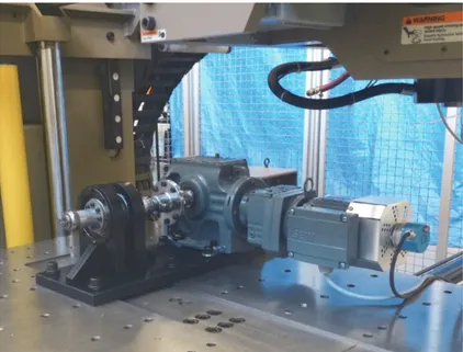
Fig. 1 shows details of the clamping system and the various components are identified as given below: 1. Precision locknut
2. Fenlock cone clamp
3. Flange connecting motor to tube drive shaft 4. Support bearings
A
R. Tovo et alii, Frattura ed Integrità Strutturale, 36 (2016) 119-129 DOI: 10.3221/IGF-ESIS.36.10
121
5. Tube to shaft coupling 6. Motor keyway lock bolt
The process of aligning the tubes and clamping them in position for welding is quite time-consuming and any extension of this process into industry would require an increased level of automation to be introduced into the process compared with this prototype. Key issues in the clamping process include achieving accurate alignment which is fundamental to achieving a high quality weld; heat retention during welding of multiple tube specimens, which makes it increasingly difficult to release the cone clamps (probably because of expansion of the threads on the release bolts which led to replacement of a number of these bolts during the production run of 100 specimens); difficulty in achieving an even clamping force on the tubes caused by differences in ID of the tubes and by different out-of-round measurements which both lead to distortion of the tube during setup. The sequence of events during welding is outlined in Fig. 2 and it should be noted that it was found necessary to machine the tube OD to 37.5 mm to improve the tube alignment during set-up. Full details of the welding process will be reported elsewhere.
Figure 1: Illustration of a tube specimen in position ready to be welded.
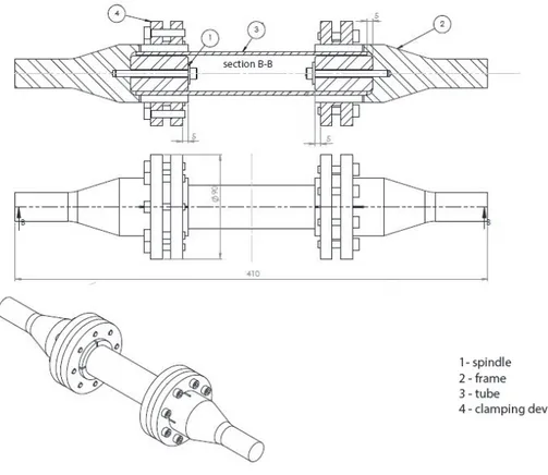
Figure 2: Schematic diagram showing the various components in the tube clamping system.
1 2 2 3 1 4 4 5 6
R. Tovo et alii, Frattura ed Integrità Strutturale, 36 (2016) 119-129; DOI: 10.3221/IGF-ESIS.36.12
122
SPECIMEN AND TESTING EQUIPMENT
he fatigue specimens consisted of two 110 mm lengths of 6082-T6 aluminium tubes joined by friction stir welding, as shown in Fig. 3.
Figure 3:Geometry of the welded tube specimens. All measurements are given in mm.
To grip the specimens in the 250 kN MTS fatigue testing machine used in this work, a pair of tube gripping fixtures were manufactured from high strength steel (see Fig. 3) that were connected to the tube by commercial clamping devices with an internal insert in the tubes to prevent deformation induced during clamping of the grips.
Figure 4: Diagram showing the tube clamping fixtures in place on a fatigue specimen.
R. Tovo et alii, Frattura ed Integrità Strutturale, 36 (2016) 119-129 DOI: 10.3221/IGF-ESIS.36.10
123 Figure 5: Complete assembled fatigue specimen and clamping fixtures.
Figure 6: The various parts of a single tube end clamping fixture.
Fig. 5 shows complete assembled fatigue specimen and clamping fixtures, while Fig. 6 shows the various parts of a single clamping fixture.
UNIAXIAL TENSILE FATIGUE TEST RESULTS
able 1 shows the fatigue data obtained from welded tube specimens tested at R = 0.1 at frequencies between 10-25 Hz. Test run-out was deemed to have occurred if the specimen survived 2,000,000 load cycles.
Specimen Range [MPa] Cycles Run out
W128 102.90 67,970 W122 82.32 96,400 W124 61.74 466,154 W120 56.60 1,167,540 W112 51.45 2,000,000 x W129 102.94 37,991 W130 56.60 222,671 W117 56.60 709,775 W118 51.45 1,247,627 W113 56.60 2,000,000 x
Table 1: Fatigue data obtained at R = 0.1.
R. Tovo et alii, Frattura ed Integrità Strutturale, 36 (2016) 119-129; DOI: 10.3221/IGF-ESIS.36.12
124
Tab. 2 shows the fatigue data obtained with a stress ratio R = -1.
Specimen Range [MPa] Cycles Run out
W115 102.94 697,953 W111 154.36 19,763 W127 138.92 81,298 W114 92.61 463,257 W123 77.18 2,000,000 x W116 92.61 2,000,000 x W119 154.36 17,200 W121 92.61 476,829 W125 82.35 2,000,000 x W115 102.94 697,953
Table 2: Fatigue data obtained at R = -1.
CRACK INITIATION SITE
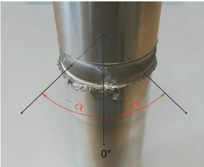
rack initiation sites are defined in terms of their angular position relative to the end point of the weld, given as 0° in Fig. 7 where the advancing side of the weld is towards the top in the figure, and the retreating side is towards the bottom.
Figure 7: Coordinate system used to define the crack initiation sites.
Crack initiation was located in the advancing side of the weld in almost half of the specimens, usually closely associated with the slight undercut at the edge of the weld zone. Tab. 3 gives the location of crack initiation for all of the specimens where cracking was observed. In the two specimens that were left intact (W117: 709,775 cycles and W121: 476,829 cycles) cracking had initiated along the middle plane of the weld zone and one specimen fractured through the middle of the weld (W118: 1,247,627 cycles). The data is summarised in the bar chart shown in Fig. 8.
C
R. Tovo et alii, Frattura ed Integrità Strutturale, 36 (2016) 119-129 DOI: 10.3221/IGF-ESIS.36.10
125
Load ratio Specimen Crack initiation α [deg]
R=0.1 W128 advancing side 1 W122 advancing side 20 W124 double location -40 W120 not separated 0 W112 run out W129 advancing side -110 W130 middle -75 W117 not separated 0 W118 middle -45 W113 run out R= -1 W115 advancing side 89 W111 double location 160 W127 double location 30 W114 advancing side -95 W123 run out W116 run out W119 advancing side -135 W121 not separated W125 run out
Table 3: Crack initiation location.
Figure 8: Frequency of crack initiation by location. 0 1 2 3 4 5
advancing middle double
Sp ec im en q u ant ity Side R= 0.1 R= ‐1
R. Tovo et alii, Frattura ed Integrità Strutturale, 36 (2016) 119-129; DOI: 10.3221/IGF-ESIS.36.12
126
To further aid in identifying the various crack initiation locations relative to the end point of the weld, three zones were defined around the nugget, as seen in Fig. 9, while Fig. 10 summarises crack initiation data in terms of their frequency of occurrence in the three zones:
A: within a range of 45° around the centre of the stop position of the weld B: within a range of 22.5° outside zone A in both directions (α+ and α-) C: the remainder of the weld circumference
Fig. 10 gives a bar chart summarising the frequency of crack initiation as in each weld zone, while Figs. 11-13 respectively give illustrative examples of the crack paths associated with crack initiation at the advancing side undercut, the middle of the weld zone, and double crack initiation.
Figure 9: Definition of the 3 zones around the weld circumference.
Figure 10: Number of crack initiation sites in each zone.
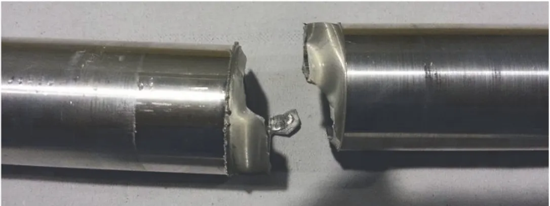
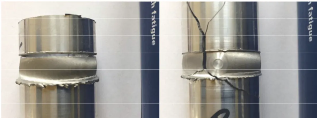
Figure 11: Typical advancing side crack path (W114). Figure 12: Crack path associated with crack initiation in the middle of the weld zone (W130).
R. Tovo et alii, Frattura ed Integrità Strutturale, 36 (2016) 119-129 DOI: 10.3221/IGF-ESIS.36.10
127
Fatigue crack paths were clearly influenced by crack initiation sites and could therefore exhibit crack path deviation across the weld zone, as is clearly shown in Fig. 12 for the case of initiation sites at the undercut at both edges of the weld; the crack has grown faster along the advancing side and then moved across to the retreating side. Where the crack path remained in the middle of the weld zone, this appeared to be associated with the presence of porosity defects in the weld. [7]. Crack initiation in the middle of the weld is uncommon and the metallurgical reasons for this behaviour are still being investigated. Figures 14 and 15 give SEM images of typical initiation sites in specimens W111 (19,763 cycles) and W121 (476,829). It is clear that in both cases initiation is associated with the small local stress concentrations due to the tool shoulder marks arising from the tool advance during a single tool rotation
Figure 14: Crack initiation site in specimens W111 (marked with arrow).
R. Tovo et alii, Frattura ed Integrità Strutturale, 36 (2016) 119-129; DOI: 10.3221/IGF-ESIS.36.12
128
TORSION TESTS
igs. 16 and 17 show typical crack paths for specimens tested in fatigue under pure torsion loading.
Figure 16: Example of torsion test, T2 and T6 (R=-1, stress amplitude = 42 MPa).
Figure 17: Example of torsion test, T11 (R-1, stress amplitude = 66 MPa) and T16 (R=0, stress amplitude = 33 MPa).
It is clear that the crack paths are considerably more complex under torsional loading and that some specimens do not show the classic 45° torsional crack propagation; for example, T2 resembles a pure tensile fracture. Others specimens present multiple crack propagation paths (e.g. T6) and T16. Further details of the torsion tests performed can be obtained in reference [6].
CONCLUSIONS
he two different load ratios used in the tensile fatigue loading (R= 0.1 and -1) gave very similar crack initiation behaviour. Despite the unusual geometry of the FSW joint studied, most of the specimens exhibited crack initiation on the advancing side of the weld, associated with the marks arising from tool advance during a single tool rotation and usually in the proximity of the stop-start zone, as reported in other papers [7, 8, 9]. A few specimens behaved differently, exhibiting changes in the plane and direction of crack propagation (W124, T6). Further metallurgical analysis is underway to identify the reasons for these behaviours.
ACKNOWLEDGEMENTS
he Leverhulme Trust is gratefully acknowledged for the award of an international network grant IN-2012-107.
F
T
T
R. Tovo et alii, Frattura ed Integrità Strutturale, 36 (2016) 119-129 DOI: 10.3221/IGF-ESIS.36.10
129
REFERENCES
[1] Tra, T. H., Okazaki, M., Suzuki, K., Fatigue crack propagation behavior in friction stir welding of AA6063-T5: Roles
of residual stress and microstructure,International Journal of Fatigue, 43 (2012) 23–29.
[2] Ilman, M.N., Kusmono, P.T. Iswanto, Fatigue crack growth rate behaviour of friction-stir aluminium alloy AA2024-T3 welds under transient thermal tensioning, Materials and Design, 50 (2013) 235–243.
[3] K. Sillapasa, S. Surapunt, Y. Miyashita, Y. Mutoh, N. Seo, Tensile and fatigue behavior of SZ, HAZ and BM in friction stir welded joint of rolled 6N01 aluminum alloy plate, International Journal of Fatigue, 63 (2014) 162–170. [4] M.N. James, D.G. Hattingh, G.R. Bradley, Weld tool travel speed effects on fatigue life of friction stir welds in 5083
aluminium, International Journal of Fatigue, 25 (2003) 1389–1398.
[5] Edwards, P., Ramulu, M.,Fatigue performance of Friction Stir Welded Ti-6Al-4V subjected to various post weld heat
treatment temperatures, International Journal of Fatigue, 75 (2015) 19-27.
[6] Hattingh, D. G., James, M. N., Susmel, L., Tovo, R., Multiaxial fatigue of aluminium friction stir welded joints:
preliminary results, Frattura ed Integrità Strutturale, 33 (2015) 382-389; DOI: 10.3221/IGF-ESIS.33.42.
[7] Ren, S.R., Ma, Z.Y., Chen, L.Q., Effect of welding parameters on tensile properties and fracture behavior of friction stir welded Al–Mg–Si alloy, Scripta Materialia, 56 (2007) 69–72.
[8] Liu, H.J., Fujii, H., Maedaa, M., Nogi, K., Tensile properties and fracture locations of friction-stir-welded joints of
2017-T351 aluminum alloy,Journal of Materials Processing Technology, 142 (2003) 692–696.
[9] Sutton, M. A., Reynolds, A. P., Yang, B., Taylor, R., Mixed mode I/II fracture of 2024-T3 friction stir welds, Engineering Fracture Mechanics, 70 (2003) 2215–2234.