Main Process for the logical control of the
HELENA loop
I. Di Piazza, M. Tarantino, P. Gaggini
Report RdS/2013/052
MAIN PROCESS FOR THE LOGICAL CONTROL OF THE HELENA LOOP
I. Di Piazza, M. Tarantino, P. Gaggini (ENEA) Settembre 2013
Report Ricerca di Sistema Elettrico
Accordo di Programma Ministero dello Sviluppo Economico -‐ ENEA Piano Annuale di Realizzazione 2012
Area: Produzione di energia elettrica e protezione dell'ambiente
Progetto: Sviluppo competenze scientifiche nel campo della sicurezza nucleare e collaborazione ai programmi internazionali per il nucleare di IV Generazione
Obiettivo: Sviluppo competenze scientifiche nel campo della sicurezza nucleare Responsabile del Progetto: Mariano Tarantino, ENEA
Index
1. Introduction ...3
2. Inertization And Conditioning (Empty Facility) ...6
3. Pre-Heating Of The Loop ...6
4. Filling ...6
5. Stand-By Condition (Heating Cables Control) ...7
6. Secondary Loop Startup On Bypass ...8
7. Forced Circulation Under Isothermal Condition (Pump)...9
8. Valve Test Section Procedure ... 10
9. Full Power Forced Circulation Test ... 12
9.1 Secondary Loop Startup ... 12
10. Forced Circulation Test In DHR Conditions... 12
10.1 Secondary Loop Startup ... 13
11 Recovery Of The Lead Pump Leakage ... 13
12 Secondary Loop Draining ... 15
12.1 Hx Shell Section Drain ... 15
12.2 HX Shell + Bypass loop drain ... 15
13 Primary Loop Draining ... 16
1. Introduction
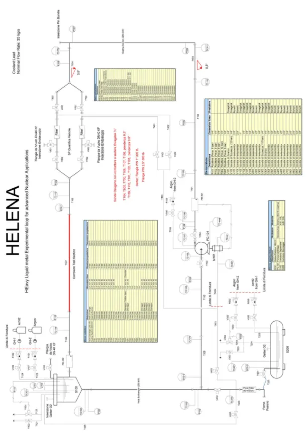
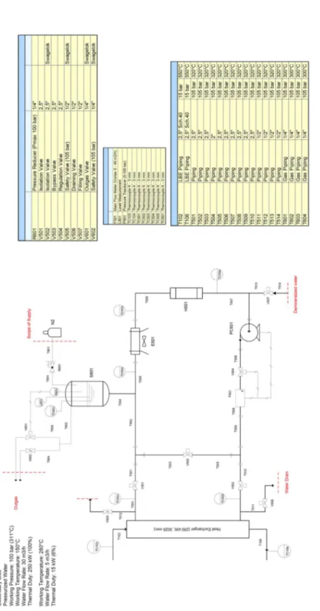
The present document reports the main procedures for the logical control of the HELENA facility. The reference for the piping and instrumentation is the P&ID reported in Figure 1 for the primary side, where all the instrumentation, components and pipes are listed and logically represented. The secondary side, filled with pressurized water at 100 bar, is described in Figure 2 where the P&ID is depicted as a reference for the procedures.
The whole facility includes:
1. the Primary side, filled with pure Lead, with 2 ½″ S40 pipes, where some main components are placed:
ü a prototypical pump, operating in the range 10-50 kg/s, with BEP mass flow rate 30-40 kg/s and BEP pressure head 3.5-5 bar;
ü a Shell and tube Heat Exchanger (HX), with 7 tubes in tubes with stainless steel power in the gap, operating in the range 10-250 kW;
ü a high mass flow rate Venturi flow meter (3-40 kg/s) FM102;
ü a test valve section (T700, T800, V701, V702, V801, V802) to test prototypical ball valves in pure Lead;
ü a corrosion-erosion test section T107;
ü a Fuel Pin Simulator (19-pins) 250 kW power: to be installed later, at the moment is replaced by a tube;
2. the Secondary side, filled with water at 100 bar, connected to the HX, shell side. It includes a pump PC501, an air-cooler E501, by-pass and isolation valves, a heater H501, and a pressurizer S601 with cover gas;
3. an ancillary gas system, to ensure a proper cover gas in the expansion tank;
4. Aa Lead draining section, with ½″ pipes, isolation valves and a storage tank (S200);
The main procedures include all the transient and steady state conditions to be performed in the facility to prepare the loop or for the normal operation, and to assess the goals of the experimental campaigns. The procedures define the process of the facility and the logical control must operate this process.
Figure 1 Piping and Instrumentation Diagram (P&ID) of the HELENA facility: Lead-filled primary side.
Figure 2 Piping and Instrumentation Diagram (P&ID) of the HELENA facility: water-filled secondary side.
2. Inertization And Conditioning (Empty Facility)
The Inertization consists of in the pre-oxidation of stainless steel working in lead and the successive filling of the loop with Argon. For the pre-oxidation of the stainless steel pipes and components which are in contact with the liquid metal during the normal operation of the facility, the pipes and components must be pre-heated with the heating cables up to 100 °C and this temperature must be kept constant for 24 hours with flowing air in the pipes. The time derivative of the temperature during the heating process can be fixed to 10 °C/h, to mitigate thermal stresses in the loop and to preserve the integrity of the structure. This phase is operated to enhance a oxide layer on steel surface aiming to improve the corrosion resistance of the structures in flowing lead.
After the inertization, the Conditioning phase is carried out. Keeping components at 100 °C, 10-15 Cleaning Cycles are performed. Each Cleaning Cycle consists on loop pressurization with Argon at 1.5 bar absolute pressure, ensured by the set point of the pressure transducer P111 fixed to 1.5 bar absolute. This condition is kept for 5 minutes and therefore Argon is discharged by the V101 gas drain valve. This phase is operated to extract the oxygen from the loop and stainless steel matrix and thus minimizing lead oxidation when the loop is filled.
After the Cleaning cycles, the loop is filled with Argon through V107, with the pressure transducer P111 set point fixed to 0.2 bar gauge pressure (1.2 bar absolute pressure). The loop is set at 100 °C and it is isolated from the environment and it is ready for the next pre-heating step.
3. Pre-Heating Of The Loop
The set temperature of the primary loop is fixed to 400 °C, and the components are heated-up by the heating cables with a heating rate of 10 °C/h. Therefore the pre-heating duration time will be around 30 h. The pressure increase ratio can be evaluated through the perfect gas law and it is of the order p400°C/p100°C~673/273~2.46, i.e. the final maximum theoretical pressure for a constant volume closed
system is 3.2 bar absolute, 2.2 bar gauge. Nevertheless, the overpressure is discharged by the gas drain valve V101 during the operation and the overpressure peak should not pass 0.5 bar gauge. At the end of the pre-heating, the loop is filled with Argon at constant temperature T=400°C and pressure p(gauge)=0.2 bar. To obtain this final state the set point of P111 must be set to 0.2 bar gauge, and the DACS system will drive the V101 and V107 valves in the proper way.
4. Filling
The filling operation is carried out by opening the drain/fill isolation valves V201, V202, and the drain gas valves V101 with P111 set to 0.2 bar gauge, and by pressurizing the S200 cover gas through the pressure regulator R302. The R302 pressure level will be increased gradually up to ~6 bar absolute, by fixing the P200 set point to 6 bar, until the desired Lead level is reached in the loop by a proper signal of the Lead high level sensor L101 in the expansion vessel S100. The DACS will regulate both V302 (Argon inflow) and V304 (Argon drain) in order to keep the pressure in the S200 cover gas to the desired set point. The operation is finished when the hydrostatic equilibrium has been reached and the loop is completely filled with Lead up to L101 level. Then, the S200 storage tanks is isolated by
closing V201, V202 and the pressure level in the S200 cover gas is decreased gradually down to 0.2 bar gauge, by fixing a proper set point in P200.
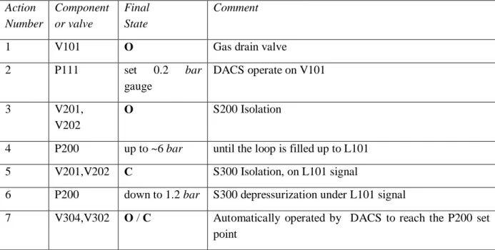
The sequence of operations to be performed to fill the loop with Lead is summarized in Table 1.
Table 1 Components and valve configuration for the filling of the facility.
Action Number Component or valve Final State Comment
1 V101 O Gas drain valve
2 P111 set 0.2 bar gauge DACS operate on V101 3 V201, V202 O S200 Isolation
4 P200 up to ~6 bar until the loop is filled up to L101
5 V201,V202 C S300 Isolation, on L101 signal
6 P200 down to 1.2 bar S300 depressurization under L101 signal
7 V304,V302 O / C Automatically operated by DACS to reach the P200 set
point
5. Stand-By Condition (Heating Cables Control)
The stand-by condition (SBC) is kept when the primary loop is filled with Lead and the secondary water side is drained. The set temperature is fixed to a value between 400°C and 450 °C, and the DACS controls the heating cables in order to reach the fixed temperature. The maximum grow rate is fixed to 10 °C/h. Each pipe of the primary side has its own heating cable (i.e. T101-T110, T700, T702, T800, T802) and the HX shell is traced by heating cables. The generic section of the pipe is shown in
Figure 3.
Figure 3 Generic section of a primary pipe with heating cable and thermocouples.
Each Heating cable will refer to a ‘control’ thermocouple TCC for control, and to a ‘safety’ thermocouple TCS as backup thermocouple for the control system. The ‘wall’ thermocouple TCW
will monitor the wall pipe temperature but it will not be part of the control system. In this way, the heating cables will be preserved from braking. The heating cables will operate on a ON/OFF logic without PID. The thermal capacity of the system is so large that this control philosophy does not produce relevant oscillations in the Lead temperature.
6. Secondary Loop Startup On Bypass
The secondary loop is filled with water and pressurized up to 100 bar by the S601 pressurizer with cover gas. To preserve the integrity of HX, it is necessary to startup the secondary loop circulation with bypass and pre-heating. First, the isolation valves V501 and V502 are closed and V503 is open in order to establish bypass and insulating the HX shell. Then the secondary loop is filled with demineralized water by opening V507, until the water level in the pressurizer S601 has reached a pre-fixed value monitored by the level sensor L601. After this, the S601 cover gas is pressurized with Nitrogen (N2) by setting the pressure set point P601 to 100 bar absolute, with a water saturation
temperature Tsat,16bar~311 °C. The DACS will operate on V601 to reach the set point P601. The
circulation pump PC501 is switched on, and the H501 heating section is switched on until a fixed temperature ~230 °C is reached, with the fluid ~80°C undercooled. The pre-heating list of actions for the secondary side is summarized in Table 2.
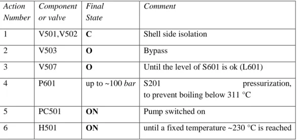
Table 2 Components and valve configuration for the filling and pre-heating of the secondary side with bypass. Action Number Component or valve Final State Comment
1 V501,V502 C Shell side isolation
2 V503 O Bypass
3 V507 O Until the level of S601 is ok (L601)
4 P601 up to ~100 bar S201 pressurization,
to prevent boiling below 311 °C
5 PC501 ON Pump switched on
6 H501 ON until a fixed temperature ~230 °C is reached
To fill the shell side with water, V501 and V502 are open gradually, and the shell side HX is filled with water. After this, the bypass valve V503 is closed and the secondary loop is completely filled with water. The gas contained in the HX shell side before the water filling can be discharged through T504 and the gas drain valve V601 connected to the S601 cover gas. The volume of water needed to fill the HX shell with water is ~170-200 l. Therefore, the volume of the pressurizer is set-up to be sufficient to compensate this volume variation, i.e. S601 must be dimensioned on the volume of the secondary loop and the HX shell. The pressure of the cover gas in the pressurizer is fixed to 100 bar by P601 during all the transient.
The control system must have the possibility to set the temperature of the secondary side to a fixed value and to reach that goal by acting on E501 and secondary heating section H501 independently of the secondary side mass flow rate.
Table 3 Components and valve configuration for the filling of the HX shell side.
Action Number Component or valve Final State Comment 1 P601 up to ~100 bar S201 pressurization,
to prevent boiling below 311 °C
2 V501,V502 O HX Shell isolation valves opened gradually
3 V503 C Bypass valve
7. Forced Circulation Under Isothermal Condition (Pump)
The forced circulation in the HELENA loop is ensured by the mechanical pump PC-101. The pump has been designed on a BEP in Lead 3-4 bar, 30-40 kg/s.
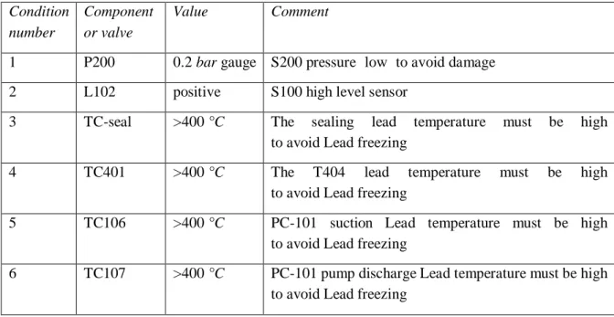
Before switching on the mechanical pump PC-101, DACS must be a priori check a few conditions in order to preserve the mechanical integrity of the pump itself. The list of conditions to be verified by the DACS system is reported in Table 4. Conditions 14 and 15 are alternative each other, and this means that Qualification valve lines T700 and T800 are used alternatively. The ‘not used’ line (for example T800) can be isolated by valves (for example V801, V802) and it is available for endoscope inspection through V901/V902.
Table 4 List of condition to be verified by DACS before starting the mechanical pump PC-101.
Condition number
Component or valve
Value Comment
1 P200 0.2 bar gauge S200 pressure ‘low’ to avoid damage
2 L102 positive S100 high level sensor
3 TC-seal >400 °C The sealing lead temperature must be high
to avoid Lead freezing
4 TC401 >400 °C The T404 lead temperature must be high
to avoid Lead freezing
5 TC106 >400 °C PC-101 suction Lead temperature must be high
to avoid Lead freezing
6 TC107 >400 °C PC-101 pump discharge Lead temperature must be high
7 V103 O PC-101 suction isolation valve
8 V104 O PC-101 discharge isolation valve
9 V108 O PC-101 cover gas isolation valve
10 V403 O PC-101 sealing-leakage line T403 isolation valve
11 V201 O S200 Lead isolation valve
12 V405 C Leakage re-pumping line T405 isolation valve
13 V202 C Loop drain isolation valve
14 V801, V802 O Valve qualification section T800
15 V701, V702 O This condition is alternative to condition 14
After the verification of conditions reported in Table 4, the pump is started by an inverter, increasing gradually the rotation rate up to the nominal value. To start up the pump PC-101, the loop must be filled and in isothermal condition, i.e. the list of actions in sections 0, 3, 4, 0 must be carried out previously. Therefore, the heating cables must be switched on and controlled by DACS to a set point between 400 and 450 °C.
The test duration time scheduled for the forced circulation under isothermal condition at the nominal mass flow rate (30-40 kg/s) is 4000 h, i.e. ~6 months.
8. Valve Test Section Procedure
One of the purposes of the HELENA facility is to test ball valves in flowing Lead.
A proper test section is present, lines T700 and T800, valves V701, V702, and V801, V802. First of all, the two branches T700 and T800 of the valve qualification test section, will be operated alternatively, i.e. T700 will be in flowing lead when T800 is isolated and drained, and vice-versa. When the T700 line is open to test the valves V701 and V702, the T800 line is drained by closing V801, V802 and opening the V402 drain isolation valve. When the T800 line is drained, V402 is closed again, the temperature of the branch is set on 50°C and the line can be inspected by endoscope though V901 vacuum flange. The pre-requisite for the T800 draining is that V403, V201 are open and P200 is set to 0.2 bar gauge.
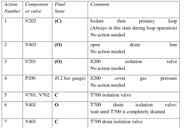
The list of actions to drain the T700 and T800 line are reported in Table 5 and Table 6 respectively. The test duration time scheduled for each branch (T700 or T800) of the valve test section at the nominal mass flow rate (30-40 kg/s) is 1000 h, i.e. ~1.5 months. After the test, the branch will be drained and inspected by endoscope the vacuum flange.
Table 5 List of actions for the draining of the T700 line. Action Number Component or valve Final State Comment
1 V202 (C) Isolate then primary loop
(Always in this state during loop operation) No action needed
2 V403 (O) open drain line
No action needed
3 V201 (O) S200 isolation valve
No action needed
4 P200 (0.2 bar gauge) S200 cover gas pressure
No action needed
5 V701, V702 C T700 isolation valve
6 V401 O T700 drain isolation valve:
wait until T700 is completely drained
7 V401 C T700 drain isolation valve
Table 6 List of actions for the draining of the T800 line.
Action Number Component or valve Final State Comment
1 V202 (C) Isolate then primary loop
(Always in this state during loop operation) No action needed
2 V403 (O) open drain line
No action needed
3 V201 (O) S200 isolation valve
No action needed
4 P200 (0.2 bar gauge) S200 cover gas pressure
No action needed
5 V801, V802 C T800 isolation valve
6 V402 O T800 drain isolation valve:
wait until T800 is completely drained
9. Full Power Forced Circulation Test
For this type of test, the pump is activated, according to the procedure described in Section 7. Then, the power ramp of the bundle is started (ramp time 1-5 min) to an intermediate value of 20 kW, the heating cables of the primary side are switched off. The high power section of the HX is filled
according to the procedure described in section 6, with water mass flow rate of 10 m3/h.
The power of the bundle is now increased gradually from 20 kW up to 200-250 kW, and the water
mass flow rate in the HX is increased up to 30 m3/h and the HX-inlet set temperature of the secondary
fluid (pressurized water at 100 bar) is fixed to ~230 °C. The exact value of both secondary mass flow rate and inlet water temperature will depend on the Lead temperature and the DACS will drive the correct choice for the values.
With the present pump forced circulation, if the mass flow rate will be of the order of 30-40 kg/s, the bundle can be operated at the maximum power 200-250 kW, and the integrity of the pins is ensured. In fact, setting to 80 °C the maximum allowable temperature drop in the bundle to have clad temperatures lower than 550 °C, the maximum allowed power to the bundle is:
max 35 145 80 410
Bundle p
Q =m c& D »T × × » kW
(1)
9.1 Secondary Loop Startup
The secondary loop is started-up with bypass according to what described in section 6. Then, the secondary water temperature is fixed to a value ~70-80 °C lower than boiling temperature at 100 bar, i.e. T<Tsat-70°C~230 °C, and the DACS will reach the goal with a typical time constant of half an
hour. The secondary water mass flow rate, measured by FM201, will be fixed according to the power to exchange and it will be around 30 m3/h for the full power 250 kW or less for lower power. The temperature level will be set by the experimentalist according to the primary temperature and to the power to exchange basing on the experience and on pre-test CFD calculations.
10. Forced Circulation Test In DHR Conditions
In this type of test, the power of the bundle is in the range 10-30 kW, to reproduce a pin wall heat flux typical of the decaying power, 5-7% of the nominal heat power, i.e. ~12 kW for the 19-pin bundle,
corresponding to qʺ~50-70 kW/m2.
In this type of test, the pump is activated just before starting the bundle power. The mass flow rate is fixed to 1-6 kg/s according to the bundle power.
In this type of test, the power of the bundle must not exceed 30 kW. Once the power level has been fixed to 10<Q*<30 kW, the heating cables are switched off and the power ramp is started. The ramp time will be fixed between 1 min and 5 min.
Then the secondary loop is started-up according to the indications provided in section 0. The test has a typical time scale of a few hours and it is finished when the steady-state condition is reached both for the primary and for the secondary loop.
10.1 Secondary Loop Startup
The secondary loop is started-up with bypass according to what described in section 6. Then, the secondary mass flow rate is fixed to 5 m3/h and the secondary water temperature is fixed to a value ~200 °C; the DACS system will reach the goal with a typical time constant of half an hour. The temperature level will be set by the experimentalist according to the primary temperature and to the power to exchange basing on the experience and on pre-test CFD calculations.
11
Recovery Of The Lead Pump Leakage
During operation, the pump will suffer by design of a continuous leakage from the packing seal. This leakage will be drained through T403, T404, T200 in S200. The level of lead in the loop will go down gradually and therefore the loop must be refilled periodically with Lead. In any case the Lead level in the facility must be in between L101 and L102.
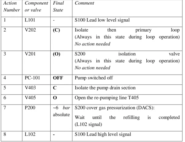
The re-filling procedure can be activated by DACS on low level Lead signal L101, and the S200 will be pressurized refilling the loop through T405 line; the operation will be stopped by L102 Lead high level signal in S100. The recovery of the pump leakage can be carried out with the pump switched off or with pump operating at nominal flow rate. The most safe way is to switch off the pump during operation. The detailed list of actions to be performed in this latter case is reported in Table 7.
Table 7 List of actions for the recovery of the Lead pump leakage in a safe way by switching-off PC-101 during the procedure.
Action Number Component or valve Final State Comment
1 L101 - S100 Lead low level signal
2 V202 (C) Isolate then primary loop
(Always in this state during loop operation) No action needed
3 V201 (O) S200 isolation valve
(Always in this state during loop operation) No action needed
4 PC-101 OFF Pump switched off
5 V403 C Isolate the pump drain section
6 V405 O Open the re-pumping line T405
7 P200 ~6 bar
absolute
S200 cover gas pressurization (DACS):
Wait until the refilling is completed
(L102 signal)
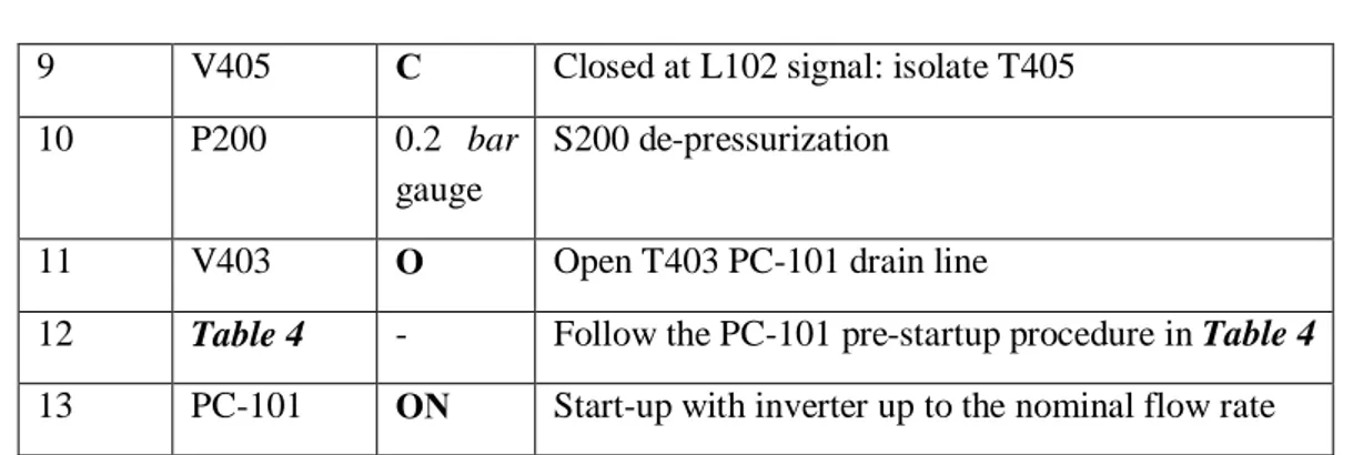
9 V405 C Closed at L102 signal: isolate T405
10 P200 0.2 bar
gauge
S200 de-pressurization
11 V403 O Open T403 PC-101 drain line
12 Table 4 - Follow the PC-101 pre-startup procedure in Table 4
13 PC-101 ON Start-up with inverter up to the nominal flow rate
The first time it is operated, the procedure must follow the indications provided in Table 7. The practical experience will give the correct feedback if it is possible to operate the Lead leakage re-pumping with the PC-101 switched-on at nominal mass flow rate, i.e. without stopping flow circulation in the loop. The list of actions to operate the leakage pumping without switching-off PC-101 is reported in Table 8.
Table 8 List of actions for the recovery of the lead pump leakage without switching-off PC-101 during the procedure.
Action Number Component or valve Final State Comment
1 L101 - S100 Lead low level signal
2 V202 (C) Isolate then primary loop
(Always in this state during loop operation) No action needed
3 V201 (O) S200 isolation valve
(Always in this state during loop operation) No action needed
4 PC-101 (ON) Pump kept ON
No action needed
5 V403 C Isolate the pump drain section
6 V405 O Open the re-pumping line T405
7 P200 ~6 bar
absolute
S200 cover gas pressurization (DACS):
Wait until the refilling is completed (L102 signal)
8 L102 - S100 Lead high level signal
9 V405 C Closed at L102 signal: isolate T405
10 P200 0.2 bar
gauge
S200 de-pressurization
12 Secondary Loop Draining
The draining of the secondary side can be operated by the water drain isolation valve V506. Conceptually, it can be operated in 2 alternative ways:
1. HX Shell section drain; 2. HX Shell + Bypass loop drain.
Phases 1 must be operated if the active section of the HX must be drained, but the bypass loop must be maintained fill for further experiments. Phase 2 must be operated if the whole secondary loop must be drained. Phase 1 and 2 are alternative and cannot be operated in sequence.
12.1 Hx Shell Section Drain
If the shell section of the HX is filled and must be drained, a bypass flow must be firstly maintained by opening the bypass valve V503, and the V501 and V502 isolation valves must be closed in order to isolate the shell section and the section can be drained by opening V506.
In this case, the demineralized water contained in the bypass loop can be saved and not drained, keeping it at the environmental temperature (20 °C) and 1 bar gauge pressure, by setting the P601 set point to 2 bar. In this case both the pump, the air-cooler and the heating section H501 can be switched off, once the goal environmental temperature has been reached. The bypass secondary loop reaches the Cold stand-by water-filled condition (CSFC), T=20 °C, p=2 bar. The list of actions is reported in
Table 9.
Table 9 List of actions for the HX shell section drain and CSFC.
Action Number Component or valve Final State Comment
1 V503 O Wait until the loop is completely drained
2 V501, V502 C Wait until the pump is completely drained
3 V506 O HX drain
4 H501 OFF
5 TBypass 20 °C Cold-down the bypass secondary loop
to the environment temperature
6 PC501 OFF Secondary pump switched OFF
7 P601 1 bar gauge Bypass Cold stand-by pressure
(CSFC state)
12.2 HX Shell + Bypass loop drain
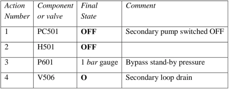
Otherwise, if the secondary HX must not be used for a long time (i.e. 1 month) for other experimental tests, the whole secondary loop can be drained, by stopping the pump circulation PC501, setting the P601 set point to 2 bar and opening V506 drain valve. The list of actions is reported in Table 10.
Table 10 List of actions for the ‘HX shell section + Bypass loop’ drain. Action Number Component or valve Final State Comment
1 PC501 OFF Secondary pump switched OFF
2 H501 OFF
3 P601 1 bar gauge Bypass stand-by pressure
4 V506 O Secondary loop drain
13
Primary Loop Draining
The primary loop draining must be operated after the secondary loop draining for safety reasons. The P111 (S100, expansion tank) and P200 (S200, storage tank) set points are set to 1.2 bar, 0.2 bar gauge. The
PC-101 pump is switched off to preserve from braking. The loop is set to a stand-by condition (SBC)
described in section 0 with a set temperature Tloop ~400 °C. The S200 set point for temperature is set to
400 °C. When the temperature set point in the storage tank has been reached, the Lead drain valves V201 and V202, and the pump drain valve V403 are open and the Lead can drained from the loop to the S300 storage tank. When all the Lead has been drained, V201, V202 and V403 are closed again and the S200 tank isolated. The list of actions is summarized in Table 11.
Table 11 List of actions for the primary loop draining.
Action Number Component or valve Final State Comment
1 P111 1.2 bar S100 cover gas pressure
2 P200 1.2 bar S200 cover gas pressure
3 PC-101 OFF Pump switched OFF
4 Tloop 400 °C SBC described in section 0
4 T S200 400 °C Wait until S200 T has reached the set point
5 V201, V202 O Wait until the loop is completely drained
6 V403 O Wait until the pump is completely drained
7 V201, V202 C
14. Nomenclature
CSFC Cold stand-by water-Filled Condition
O Open Valve
C Closed valve
ON Component in service
OFF Component switched off