Low Cost and Fast Development of 3D Printed Gloves for 10 Degrees
of Freedom Gesture Recognition
Antonio Pallotti1,2, Mariachiara Ricci1, Giancarlo Orengo1 and Giovanni Saggio1 1Department of Electronics Engineering, University of Rome Tor Vergata, via Politecnico 1, 00133, Rome, Italy
2Technoscience, San Raffaele University of Rome, via di Val Cannuta 247, 00166, Rome, Italy
Keywords: Sensorial Glove, Resistive Flex Sensors, 3D Printing, Hand Motion Capture.
Abstract: The decreasing cost allows easy access and diffusion of 3D printers even for domestic use in the same way as 2D printers. The present work proposes the development of a sensorial glove in 3D printing, featuring low cost, easy reproduction and replacement. A 3D desktop printer, that was able to extrude different plastic materials, was used. In order to generate the geometric shape that best suited the hand anatomy, the 3D CAD design was based on hand photos from the top and the sagittal section. The design of the glove includes the sensor housings, which are pockets within which the sensor can slide during joint bending. The wiring of 10 flex sensor and the acquisition board designed for a Lycra glove were easily applied to the printed glove without modification. The glove in 3D printing was able to control virtual or mechanical hands, which provides for surgical, military, space and civil applications. The possibility to achieve waterproofing allows the use in applications that require contact with solvents or water. A standard test applied to six healthy subjects demonstrated that the proposed glove achieves performances, in terms of repeatability, reproducibility and reliability, comparable to that of the other literature gloves.
1 INTRODUCTION
Man is being able to receive stimuli from the external environment through the senses and to carry out operations through actuators such as legs for locomotion and hands for the grasping or manipulation of objects (Liu, 2011). The cognitive functions dedicated to the hands are those most expressed by the brain and can be investigated through the measurement and monitoring of motor tasks. The instruments available for the automatic measurement of hand movements were initially mechanical goniometers used by specialized therapists: these goniometers take a long time (up to 30 minutes) and provide measurements of an instant and not of a movement or sequence of gestures.
The studies proposed sensors based on different physical principles (Dipietro, 2008), optical (Li, 2011), magnetic (Dipietro, 2003), inertial and magnetic (Lisini, 2017), resistive (Simone, 2007), (Gentner, 2009, Saggio, 2016), assuming that the support is an elastic fabric like Lycra or similar materials. PCB technology has been also used to build inertial based hand tracking systems (O’Flinn, 2015). The diffusion and decreasing cost of 3D printers
allows easy access even for domestic use in the same way as 2D printers. 3D printers have been already employed to build part of silicon sensory gloves (Li, 2018), but never used to build the entire glove. The present work proposes the development of a sensorial glove in 3D printing at low cost, easily reproducible and replaceable, with the possibility of waterproofing in view of applications that require it.
2 MATERIALS
2.1 3D Printed Glove
A 3D desktop printer, model Makerbot Replicator 2, that was able to extrude different plastic materials, was used in this work. In order to generate the geometric shape that best suited the anatomy of the hand, hand photos from top and lateral view were taken, to yield the edge of the hand and the height of the glove in 3D printing. Solidworks was used for the CAD design of the glove. As with the Hiteg glove, the 3D printed glove was considered to be of standard size. After the Hiteg glove (Sbernini, 2018) was worn,
a first photo was taken, so that the back of the hand was visible, and a second photo was taken sideways, so that the profile of the hand was visible. The first geometric edge of the worn glove was automatically extracted by a Matlab code. The .fig image containing the edge of the glove was converted into a .sldprt file to be processed in Solidworks. An extrusion function was performed starting from the geometric edge of the glove with a thickness of 1 mm. Thanks to the second geometric edge, extracted as for the first geometric edge, it was possible to determine the height of the extrusion. Because the anatomy of the hand is such that the size of the distal phalanxes is different from the size of the carpus, a linear function was assumed for the second geometric edge which passed through the tip of the middle index to the wrist joint. The extrusion of the first geometric edge was before carried out up to the height of the wrist and subsequently cut, linearly, to the tip of the index. Once the extrusion was cut out, the cavity was closed with a 1 mm thick top. The 3D printed glove was made in less than 5 hours from a single source file. The file contains the instructions that the 3D printer must perform to create the entire glove in a single print.
The used printer has an extruder, which is able to extrude solid with a thickness of not less than 1 mm. The material chosen for molding was Ninjaflex (thermoplastic polyurethane) from Ninjatek: once printed and solidified, the material has an elasticity proportional to the thickness of the laminated sheet, or for a slab of size x and y, of height z, the greater is the long elasticity (x, y), the smaller is the z dimension. In the same way, for a rectangular base wall, dimensions (a, b) and height c, with the same height c, the greater is elasticity, the smaller the depth
a or the width b.
To make the glove more comfortable, drilling was inserted along the main deformation axes or along the median axis of the five fingers. The drilling allowed a greater elasticity of the fabric and a greater transpiration of the hand in the glove. The design of the glove includes the housings for the flex sensors (Orengo, 2014, Orengo, 2018) (Flexpoint Sensor Systems Inc., South Draper UT, USA), which are pockets or two foils within which the sensor can slide during joint bending. The sensor was fixed to the base in order to maintain the same position. The used printer was a single extruder, so that it was possible to extrude only one filament at a time. One of the problems of 3D printing is the creation of suspended or bridged sections or sections that have no other material to lean on. Two extruder printers use a printing extruder and a support extruder that works in
parallel and prints a support that supports the suspended parts and is soluble in hot water. The melting temperature of the Ninjaflex, once printed, is 60 degrees. Despite only one extruder, the glove was made as designed and the excess filaments (due to the printer) were removed.
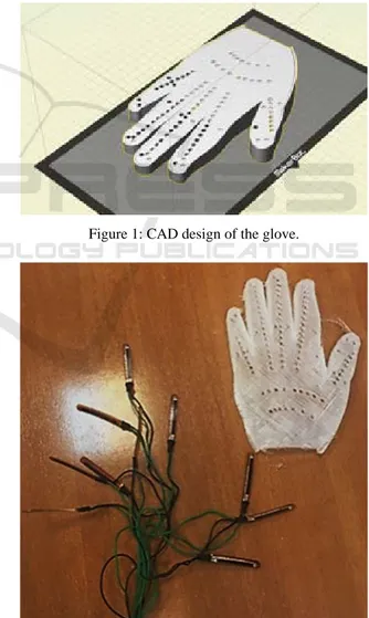
Figure 1 shows a picture of the CAD design, and Figure 2 a photo of the realized glove and the wiring of the flex sensors, taken from a Lycra glove (Sbernini, 2018) and applied to the printed glove without any modification. The 3D printed glove allows the control of hand virtual limbs, as shown in Figure 3, where the movements of the hand wearing the printed glove simultaneously control a virtual avatar and a robotic hand (Saggio, 2014), for surgical (Saggio, 2015, Sbernini, 2018), military, space and civil applications (Dipietro, 2008).
Figure 1: CAD design of the glove.
Figure 2: Flex sensors’ wiring (left down) and 3D printed prototype (right up).
Figure 3: Flat position (top) and closed hand (bottom) of the 3D printed glove (left) driving simultaneously a virtual+ hand (center) and a mechanical hand (right).
2.2 Hardware
In order to show the ease of realization and use of the 3D printed glove, a ready-made apparatus composed of the flex sensor wiring and the acquisition board, developed from the Health Involved Technical Engineering Group (HITEG) for a Lycra glove, was removed and inserted into the printed glove without any modification. The sensors were inserted into the ready and printed pockets. In this way, replacement of the glove in case of damages or need of different sizes is easy, fast and cheap.
The board, which is shown in Figure 4, is drawn in Altium Designer, has a sampling frequency of 1 KHz, the analog-to-digital resolution of 12 bits (range 0-3.3V), and communicates with the computer via USB or Bluetooth links with 64 bytes packages. In order to transduce the resistive variation signal coming from the glove sensors into an electrical potential variation, the board has 32 voltage dividers, one for each data line. The circuit provides galvanic isolation between the connection of the sensors and the parts in direct contact with the computer, in order to prevent unwanted electrical discharges onto the subject. The circuit can drive step motors, typically present in electromechanical prostheses for the movement of the ends, by inserting an optional external module called “Motor control”. The logic of the acquisition and control board was completely managed by a PIC 24EP512GU810 microcontroller (Microchip). In this case, the board was powered by the USB cable used for data transmission, otherwise, for wireless operation, it needed a battery. The board used in the present work was therefore oversized, because compatible with sensory gloves featuring up
to 32 inputs from resistive sensors: considering that the hand has 27 degrees of freedom (DoF), one can also measure the movements of the wrist. A board designed specifically for this job would have occupied a smaller space, which could be integrated into the carpus of the hand itself. The photo of the entire system, composed of the electronic board and the glove, is shown in Figure 5.
Figure 4: HITEG acquisition board for flex sensory gloves.
Figure 5: The measuring system: the sensory glove and the HITEG acquisition board.
3 TESTING
METHODS
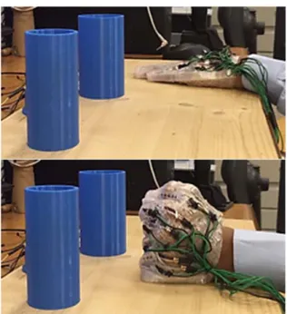
Six healthy subjects were involved in the Wise test (Wise, 1990, Dipietro, 2003), 2 males and 4 females, with an average age of 4020 years. The glove was worn by the hand and the electronic board was placed on the forearm. The measurement system consists of two areas: an area to place the hand flat on the table and an area to grab a large mold. The subject sits on a chair with his back resting against the back of the chair and his hand resting on the table. The test setup is shown in Figure 6. Before starting the test, the subject became familiar with the glove in 3D printing. All the sensors were checked to fit the glove, so that all the flexed extensions of the metacarpal joints and proximal interphalanges were detected: for the thumb, the distal and proximal interphalangeal joint were measured. Microcontroller Bluetooth port Sensor inputs Voltage divider LED USB port Galvanic isolation
Figure 6: The measurement protocol consists of two positions, one open-handed (top) and one gripping a cylindrical mold (bottom). The mold gripping position corresponds to task A and B , the flat hand position corresponds to task C and D.
The measurement protocol consisted of two tests. The first test, performed to evaluate repeatability, was composed of the task A and C. In the task A, the subject placed the hand on the mold and grasped it, 6 seconds were recorded in this position, then, in the task C, the subject places the hand resting on the table and 6 seconds were recorded in this position. This test was repeated 10 times (or 10 trials): this set of measures was called a block. Both in task A and task C, the measurement system was never removed from one block to another. In the second test, performed to evaluate reproducibility, the glove was removed and worn again by the subject. This test was composed of the tasks B and D, which were the same of the tasks A and C, respectively.
The model adopted to study the behaviour of the flex sensors that make up the glove was the linear one: in task A and C a single calibration was sufficient before starting the measurement protocol. Calibration was performed by acquiring the average value on a 6-second window, while the hand was flat in the resting position on the table. The value identified was the value of Digital Minimum. The value of Digital Maximum was detected by placing the hand on the mold and grasping it for 6 seconds. The average value on this 6-second window was the Digital Maximum. To determine a correspondence between the line of angles expressed in degrees, for each articulation, and
the line expressed in digital values, for each sensor, a mechanical goniometer with a sensitivity equal to 1 degree was used. In this way, it was possible to convert the range of digital values coming from the ADC of the electronic board, in the range of angular values measured mechanically with the goniometer.
4 RESULTS
4.1 Repeatability and Reproducibility
Testing
The developed code organized data in the respective 5-dimensional Working matrix of the joint angles computed by the two measurement devices, indexed by the trial number (10), block number (10), joint number (10), position number (4) and subject (6). Then, for each position and each subject, an array
, 1, … ,10, 1, … ,10, 1, … ,10 was
finally obtained for the ith trial, in the jth block and related to the kth sensor. Another code provided tabular Wise-based Range and SD values for each subject and the mean of Range and SD values across all participants. Only the average values are shown in the present study. For each subject and each test, we defined the Range as:
jk jk k j j R max X min X (1) where 10 1 1 10
jk ijk i X X (2)is the average across the trials of each block. Then the mean of for each position was calculated across all joints. The standard deviation (SD) of the values was calculated across the blocks, then the average across the joints.
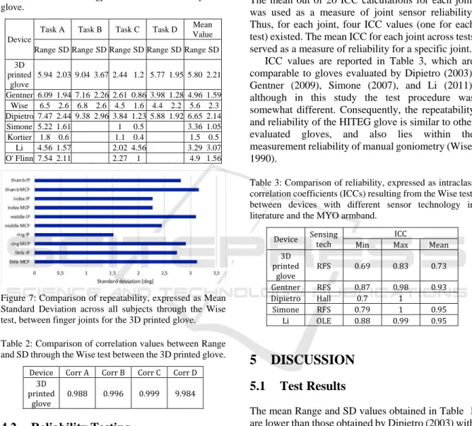
To evaluate repeatability (task A and C) and reproducibility (task B and D), Table 1 compares the full Range and SD values computed across all trials of one block, then the average across all blocks, all joints and finally all subjects, resulted from the 3D printed glove. Analysis results of Table 1 are compared with other gloves in literature based on resistive flex sensors (RFS) by Simone (2007) and Gentner (2009), inertial sensors (IMU) by Kortier (2014) and O’Flinn (2015), fiber optic sensors (Opt) by Wise (1990), Hall effect sensors (Hall) by Dipietro (2003), Optical linear encoder (OLE) by Li (2011). The mean SD across all subjects through the Wise test is reported in Figure 7 for each finger joint. For the
same measurements, data correlation between Range and SD values are reported in Table 2.
Table 1: Comparison of repeatability (task A, C) and reproducibility (task B, D), expressed as Range and SD values resulting from the Wise test, between devices with different sensor technology in literature and the 3D printed glove.
Device
Task A Task B Task C Task D Mean Value Range SD Range SD Range SD Range SD Range SD 3D printed glove 5.94 2.03 9.04 3.67 2.44 1.2 5.77 1.95 5.80 2.21 Gentner 6.09 1.94 7.16 2.26 2.61 0.86 3.98 1.28 4.96 1.59 Wise 6.5 2.6 6.8 2.6 4.5 1.6 4.4 2.2 5.6 2.3 Dipietro 7.47 2.44 9.38 2.96 3.84 1.23 5.88 1.92 6.65 2.14 Simone 5.22 1.61 1 0.5 3.36 1.05 Kortier 1.8 0.6 1.1 0.4 1.5 0.5 Li 4.56 1.57 2.02 4.56 3.29 3.07 O' Flinn 7.54 2.11 2.27 1 4.9 1.56
Figure 7: Comparison of repeatability, expressed as Mean Standard Deviation across all subjects through the Wise test, between finger joints for the 3D printed glove.
Table 2: Comparison of correlation values between Range and SD through the Wise test between the 3D printed glove.
Device Corr A Corr B Corr C Corr D 3D
printed
glove 0.988 0.996 0.999 9.984
4.2 Reliability
Testing
The reliability between measures in each test was assessed by intraclass correlation coefficients (ICCs). ICC values were calculated for each test by randomly choosing two trials out of two randomly chosen blocks for each subject. The average angles of the 6 seconds of the two trials were calculated for each subject. Then, the angle pairs of each joint from all subjects were pooled together and an ICC was calculated for each joint (Dipietro, 2003).
The ICC calculation was based on the comparison of between-subject and within-subject variance,
where the within-subject variance reflects measurement errors. If within-subject variance is low, the ICC approaches 1 and the measurements are considered as reliable. Conversely, if the ICC approaches 0, a large fraction of variance is explained by measurement errors (indicating a low reliability). The mean out of 20 ICC calculations for each joint was used as a measure of joint sensor reliability. Thus, for each joint, four ICC values (one for each test) existed. The mean ICC for each joint across tests served as a measure of reliability for a specific joint.
ICC values are reported in Table 3, which are comparable to gloves evaluated by Dipietro (2003), Gentner (2009), Simone (2007), and Li (2011), although in this study the test procedure was somewhat different. Consequently, the repeatability and reliability of the HITEG glove is similar to other evaluated gloves, and also lies within the measurement reliability of manual goniometry (Wise, 1990).
Table 3: Comparison of reliability, expressed as intraclass correlation coefficients (ICCs) resulting from the Wise test, between devices with different sensor technology in literature and the MYO armband.
Device Sensing tech ICC
Min Max Mean 3D printed glove RFS 0.69 0.83 0.73 Gentner RFS 0.87 0.98 0.93 Dipietro Hall 0.7 1 Simone RFS 0.79 1 0.95 Li OLE 0.88 0.99 0.95
5 DISCUSSION
5.1 Test
Results
The mean Range and SD values obtained in Table 1 are lower than those obtained by Dipietro (2003) with Hall sensors, but higher than Wise (1990) with optical sensors, higher than Gentner (2009) and Simone (2007) with resistive flex sensors, and much higher than O’Flinn (2015) and Kortier (2014) with inertial sensors, which get the best results but with an expensive apparatus. In the linear model of the glove, the proximal thumb finger is the one with the highest SD. It should be noted that Simone does not provide the results for the C and D tests: if the two tests had been excluded from our protocol, it would have performed a mean Range of 4.19 and a mean SD 1.62. The tasks C and D have lower values than the corresponding A and B and this is consistent with the
previous studies: placing the hand in a rest state introduces a lower error in terms of reproducibility and repeatability than the grasping of a mold, which may occur from time to time with not negligible variations. The Range values from B to A and D to C are higher, and this result is also consistent: removing the glove introduces reproducibility errors. The Range-SD correlation values for the whole test are consistent with the previous studies (Gentner, 2009). These results indicate a linear relationship between the Range and SD and furnishes a comparable estimation of measurement repeatability. The ICC=0.73 for the glove indicates a reasonable reliability.
5.2 Technical
Improvements
If a printer capable of making holes below 1 mm size had been used, it would be possible to make a smaller and more diffused drilling along the whole fabric: this would allow a further study of elasticity of the fabric with respect to the geometry of the holes (circle, square, star, sigmoid, etc.). However, drilling could result unnecessary using a more efficient extruder, to obtain 0.5 mm thick substrate, or a more elastic filament. In fact, an advantage in making a glove in 3D printing is the possibility of waterproofing: the glove can be printed as a single fabric without seams or welding or use of glues. Being a single plastic fabric, made according to the anatomy of the hand, it can be impermeable to water and then used in new applications, where the man is in contact with solvents or in applications in contact with water.
The 3D printed glove proposes applications in new environments where the natural hand can already operate, or in environments where there is no risk for the human being. A hand in boiling water suffers burns as a result of scalding. The 3D printed glove, as a sensory glove, was not designed to have thermal insulation. If the 3D printed glove was immersed in 100 degrees of boiling water, the hand itself would suffer burns. The 3D printed glove proposes a new fabric and a new manufacturing technique. Studies on heat transmission problems of ambient-hand can be carried out in future works. The Ninjaflex producer (Ninjatek) declares a glass transition temperature of 35 °C and a melting point of 216 °C. In the future, studies of the effects of pressure, temperature, humidity on the 3D printed glove could be carried out. To study the effects of these parameters on the glove worn by human hands in order to assess their safety, there must first be an approval by the scientific and ethical committee.
The proposed 3D printed glove could be a new fabric to be used in the measurement of hand movements, but currently the studies are limited only to kinematics, and do not investigate other sectors such as chemistry. The 3D printed glove has printed pockets, where the bending sensor can be inserted even during printing. In this case, the sensors were inserted once the 3D printing finished the process. Likewise, the wiring can be allocated between two layers of material during 3D printing. In this case, as a first work, the wires are visible, because the Hiteg sensor glove was reproduced, using the same sensors, wires and electronics, but changing the material of the glove's fabric. The glove with wire communication is waterproofed, if the electronics is in a non-aquatic environment. In order for the electronic board to be wearable in an aquatic environment, the electronics must be waterproofed (starting from the case), so that the electrical safety requirements are respected.
6 CONCLUSIONS
The present work proposes the development of a sensorial glove in 3D printing at low cost, easily reproducible and replaceable, equipped with 10 flex sensors. The glove design was based on hand photos, thus allowing customization of the glove shape and size, to fit the user hand. The design of the glove includes the housings for the sensors, which can be developed separately and then easily replaced, or reused in case of damages of the glove material or need of different glove sizes. The choice of drilling shape was circular, but in a future work one might think to check the influence of the drilling geometry with respect to the performance of the glove in 3D printing. In view of applications that require it, the glove can be printed as a single fabric, without seams or welding or use of glues to obtain waterproofing, and then used in new applications, where the user is in contact with solvents or water. In a future work, it will be possible to insert the sensor during the molding phase, so that it will be fixed by the printed glove without the need for stitching.
The glove in 3D printing also allowed the control of virtual or mechanical hands for surgical, military, space and civil applications.
The performances of the first prototype, evaluated with a standard test, showed the same degree of accuracy of the compared devices, except when the glove was removed and worn again, demonstrating low reproducibility due to needed improvements in glove realization, such as a more efficient extruder to
obtain 0.5 mm thick substrate or more elastic filaments.
REFERENCES
Liu, H., 2011. Exploring human hand capabilities into embeeded multifingered object manipulation. IEEE
Transactions on Industrial Informatics. 7 (3), 389-398.
Dipietro, L., Sabatini, A., M., Dario, P., 2008. A survey of glove-based systems and their applications. IEEE
Trans. on Systems, Man, and Cybernetics - Part C: Applications and Reviews. 38 (4), 461-482.
Li, K., Chen, I-M., Yeo, S., H., Lim, C., K., 2011. Development of finger-motion capturing device based on optical linear encoder. Journal of Rehabilitation
Research and Development. 48 (11), 68-72.
Dipietro, L., Sabatini, A., M., Dario, P., 2003. Evaluation of an instrumented glove for hand-movement acquisition. Journal of Rehabilitation Research and
Development. 40 (2), 179-190.
Lisini, Baldi, T., Scheggi, S., Meli, L., Mohammadi, M., Prattichizzo, D., 2017. GESTO: a glove for enhanced sensing and touching based on inertial and magnetic sensors for hand tracking and cutaneous feedback.
IEEE Trans. on Human-Machine Systems. 47 (6),
1066-1076.
Simone, L., K., Sundarrajan, N., Luoc, X., Jia, Y., Kamper, D., G., 2007. A low cost instrumented glove for extended monitoring and functional hand assessment.
Journal of Neuroscience Methods. Elsevier. 160,
335-348.
Gentner, R., Classen, J., 2009. Development and evaluation of a low-cost sensor glove for assessment of human finger movements in neurophysiological settings.
Journal of Neuroscience Methods. Elsevier. 178,
138-147.
Saggio, G., Pallotti, A., Sbernini, L., Errico, V., Di Paolo, F., 2016. Feasibility of Commercial Resistive Flex Sensors for Hand Tracking Applications. Sensors &
Transducers. IFSA. 201 (6), 17-26.
O'Flinn, B., Sanchez, J., T., Tedesco, S., Downes, B., Connolly, J., Condell, J., Curran, K., 2015. Novel smart glove technology as a biomechanical monitoring tool.
Sensors & Transducers. IFSA. 193 (10), 23-32.
Li, M. X., Wen, R., Shen, Z., Wang, Z., Luk, K., D., K., Hu, Y., 2018. A wearable detector for simultaneous finger joint motion measurement. IEEE Trans. on Biomedical
Circuits and Systems. 12, (3), 644-654.
Sbernini, L., Quitadamo, L., R., Riillo, F., Di Lorenzo, N., Gaspari, A., L., Saggio, G., 2018. Sensory-glove-based open surgery skill evaluation. IEEE Transactions on
Human-Machine Systems. 48 (2), 213-218.
Orengo, G., Lagati, A., Saggio, G., 2014. Modeling wearable bend sensor behavior for human motion capture. IEEE Sensors Journal. 14 (7), 2307-2316. Orengo, G., Saggio, G., 2018. Flex sensor characterization
against shape and curvature changes. Sensors &
Actuators_A_Physical. 273, 221-231.
Saggio, G., Bizzarri, M., 2014. Feasibility of teleoperations with multi-fingered robotic hand for safe extravehicular manipulations. Aerospace Science and
Technology. Elsevier. 39, 666-674.
Saggio, G., Lazzaro, A., Sbernini, L., Carrano, F., M., Passi, D., Corona, A., Panetta, V., Gaspari, A., L., Di Lorenzo, N., 2015. Objective surgical skill assessment: an initial experience by means of a sensory glove paving the way to open surgery simulation?. Journal of Surgical
Education. Elsevier. 72 (5), 910-917.
Wise, S., Gardner, W., Sabelman, E., Valainis, E., Wong, Y., Glass, K., Drace, J., Rosen, J., M., 1990. Evaluation of a fiber optic glove for semi- automated goniometric measurements. Journal of Rehabilitation Research and
Development. 27 (4), 411-424.
Kortier, H., G., Sluiter, V., I., Roetenberg, D., Veltink, P., H., 2014. Assessment of hand kinematics with inertial and magnetic sensors. Journal of NeuroEngineering