10
Gbit/s ALTERNATE POL,ARIZATION
SOLITON TRANSMISSION
OVER :300
km
CONTROL
STEP-INDEX FIBRE LINK
WITH NO IN-LINE
Franco
(I),
A.
Schiffini
(I),
R. Corsini
(I), NI.
Romagnoli (2), MI. Tamburrini (2),
S. Cascelli (3)
(1)
Pirelli Cavi &Sistemi, viale Sarca, 2 2 2 , 2 0 126
Milano, Italy.([email protected])
(2) Fondazione
Ugo
Bordoni,via
B.
Castiglione, 5 9 , 0 0 1 4 2 Rotma, Italy. ([email protected])(3)
IstitutoSuperiore
delleComunicazioni
e
Tecnologie
dell'hformazione.,viale
Europa.,
1 9 0 , 0 0 144
Roma, ItalyAbstract. Error-free transmission over a 300 km step-index fibre link between Roma and PoNmezia using a I O Gbit/s stream of alternate-polarization solitons was performed. Standard 10 Gbit/s SDH line terminals were used at the transmitter and receiver sides.
The growing demand for large capacity communication links is facing the problem of the already installed fibre infrastructure around the world that is mostly constituted by step-index (SI) fibres with zero dispersion at 1 . 3 ~ m . So far dispersion management and/or wavelength division multi- plexing have been demonstrated to be suitable solutions for upgrading the existing fibre infrastructure. Those solutions
require system adjustment as for instance the introduction of
dispersion compensating fibres or, in the case of WDM, an
upgrade in terms of number of channels instead of simply increasing the capacity of the single channel that would save in overall transmission bandwidth.
Fig. 1: Line configuration
I
l r
25 k m SI liher cahleIn this work, conversely, we report an optimized transmis- sion scheme that permits to improve the maximum distance
achievable on SI fibre with just a single channel, without
resorting to the insertion of in-line components (as for in- stance chirped gratings, dispersion-compensating fibres, mid-span phase-conjugators, or even synchronous ampli- tude or phase modulators). The method simply exploits the reduced interaction efficiency experienced by orthogonal solitons to increase the duty cycle in the data stream [ 11, and
it is implemented with a polarization encoder that alternates
orthogonal states of polarization in the data stream. The
effectiveness of alternate polarization encoding has been
theoretically predicted [2] and experimentally verified at 40
Gbit/s over 800 km in a dispersion-shifted fiber setup [3].
The maximum transmission distance achieved with our SI
fibre system, based on alternate polarization encoding, was
300
km
thus extending the limit of 253km
found with thedispersion supported transmission (DST) technique [4] that is another method of transmission with no in-line control.
The experimental setup is reported in Fig.(2.a). The 5 GHz
soliton pulses emitted by the so liton generator have duration
adjustable between 45 ps and 65 ps and about -3 dEm of
average power. The pulses ar'e amplified by means of a
polarization maintaining optical amplifier up to 11 dBm and sent to the polarization encoder.
Fig. 2: a) ]Polarization encoding source scheme,
b) RZ to NR25 converter
The 10 Gbit/s eiectrical data are provided by the STM-64 line terminal whose clock also drives the entire setup. The electrical signal is divided into 2x5 Gbit/s electrical bit streams by meajns of the bit divider. The two 5 Gbit/s elec-
trical bit streams are used to modulate the 5 GHz optical
pulse streams by means of Mach-Zehnder modulators. Fi-
nally, the two 5 Gbit/s optical pulse streams are time inter-
leaved by introducing a 100 p:; differential delay, and com-
bined by means, of the polarkation encoder. The output of
the whole source is a 10 Gbit/s pulse train with adjacent time slots having orthogonal polarization (alternate polari-
zation encoding). A typical eye diagram is reported in
Fig(3.a).
The link is made with a 25 km cable containing also 20 SI
fibres (ITU -T G652), looped back in pairs at a transit sta-
tion in Pomezia (25 km south1 of Rome) in order to obtain
10 spans of 50 km each. All the terminations of the spans
are located in Rome (see Figure 2). The mean attenuation,
chromatic dispersion and polarization mode dispersion of
these fibres are respectively 0.24 dB/km, D = 16.2
ECOC98, 20-24 September 1998, Madrid, Spain 95
ps/nm/km and PMD = 0.04 ps/km"2. At each span end we introduced a commercially available optical amplifier with a saturated output power of + I 4 dBm. The maximum polari-
zation dependent gain of the amplifiers was PDG = 0.3 dB,
whereas the maximum differential group delay was DGD =
1 gs.
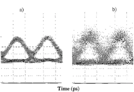
Fig. 3: Eye diagram of the 10 Ghit/s orthogonal polarization
coded signal at the output of the transmitter
(a) and after 300 km; (h).Horizontal scale 20 ps/div
a) b) . . . . , . . . . . . . . . . . . . . . . . . . . . . . . . . . . . , . . . . . . . . . . . . . ... . . . . . . Time (ps)
The configuration with all the terminations in the same lab permitted to check the quality of the transmission after each
span of 50 km by monitoring the signal just before each
amplifier. The soliton pulses at the end of the line were
detected by means of a RZ to NRZ converter placed just
before the STM-64 line terminal receiver (Fig. 2.b). The eye diagram obtained after 300 km is reported in Fig.(3.b). As it can be seen, with SO ps pulses (that is the
optimal FWHM pulse duration obtained from numerical
simulation of performance evaluation) the eye pattem is
quite clean up to 300 km, while for longer propagation dis-
tances a good transmission result can not be obtained. Several parameters were adjusted to get the best result: line input power, amplifiers gain, pulse duration.
The bit error rate (BER) measured by the receiver terminal is reported in Fig.(4) versus the power level at the preampli- fier input.
Fig. 4: BER measurement results for the source
back to hack and after each 50 km.
~ l.E-05 1 I I I I 1 I 1 .E-% 1 .E-07 1.508 1 .E-@ 1.E-10 + 300 km 1.512 1 1 I -36 -34 -32 -30 -28 -26 -24 Received Power (dBm)
As shown by BER results, after 200 km the power penalty
of the system was 1.5 dB and less then 3 dB at the end of
300 km. In this configuration, after 300 km, a BER below was achieved with a received optical power of -28 dBm. For comparison we also evaluated the system per- formance with a 10 Gbit/s bit-error rate test set. W e noticed that at 300 km of propagation distance it is possible to reach
excellent values of BER measurement down to 10." with a
Z7-l word length. With the same word length the transmis-
sion up to
SO0
km is also feasible. These results obtainedwith the short word suggest that the real limitation of the system arises from some pattern effect that is increasingly efficient the longer the pattern. In fact by resorting to de- terministic data stream we found that short pattems are more stable than longer ones.
Conclusion
.
We report the longest propagation distance of 300 kmobtained at 10 Gbit/s using conventional step-index fibre
link without any dispersion compensating technique or in- line signal control but only with optical amplification every SO km.
A c k m wledgm erzts.
M.R. and M. T. have performed this work in the framework
of the agreement between Fondazione Ugo Bordoni and the
Italian Post and Telecommunication Administration. This work has been partially carried out under the ESTHER proj- ect of European Union ACTS programme.
References
/ I / C. De Angelis, S . Wabnitz, M. Haelterman, 'Bandwidths
limits due to polarization multiplexed soliton interactions',
Electr. Lett., 29, pp.1568-1570 (1993).
F. Matera, M. Romagnoli, B. Daino, B., 'Alternate polari- zation soliton transmission in standard dispersion fibre links with no in-line controls', Electr. Lett., 31, pp.1172-
1174 (1995).
F. Favre F., D. Le Guen, M. Moulinard, M. L. Henry, P.
L. Francois, F. Devaux, T. Georges,'Single-wavelength
40 Gbit/s, 8x100 km span soliton transmission without any in-line control', EZectr. Lett., 33, pp.407-408 (1997).
B. Wedding,
B.
Franz, B. Junginger, 'lO-Gb/s opticaltransmission up to 253 km via standard single mode fiber using the method of dispersion supported transmission', J.
cfLightwave Tech., 12, pp.1720-1727 (1994). /2/
/3/
/4/
96 ECOC'98,20-24 September 1998, Madrid, Spain
![Fig. 2: a) ]Polarization encoding source scheme, b) RZ to NR25 converter](https://thumb-eu.123doks.com/thumbv2/123dokorg/8282315.130945/1.919.158.411.611.837/fig-polarization-encoding-source-scheme-rz-nr-converter.webp)