UNIVERSIT `A DEGLI STUDI DI CATANIA
Dipartimento di Ingegneria Elettrica, Elettronica ed Informatica
Dottorato di Ricerca in Ingegneria Informatica e delle Telecomunicazioni
XXVIII Ciclo
ETHERNET IN AUTOMOTIVE:
THE CASE OF IEEE AUDIO VIDEO BRIDGING
Ing. Giuliana Alderisi
Coordinatore
Chiar.ma Prof.ssa V. Carchiolo
Tutor
SOMMARIO
I veicoli moderni sono equipaggiati con pi`u di 100 sistemi embedded, detti Electronic Control Unit (ECU), che gestiscono il funzionamento del veicolo stesso. Sono ad esempio ECU i seguenti dispositivi: Engine Control Module (ECM), Powertrain Control Module (PCM), Brake Control Module (BCM), General Electric Module (GEM), e altri an-cora. Con l’incremento del numero di ECU, crescono e si evolvono le esigenze delle reti in automotive. Sempre pi`u spesso il traffico gen-erato in un dominio funzionale `e richiesto, per essere elaborato o pi`u semplicemente mostrato all’utente, da un altro dominio. Si pensi ad esempio alle ECU dedite a monitorare la temperatura del motore per avviare procedure di raffreddamento in caso di necessit`a. Le infor-mazioni rilevate da questi sistemi sono per`o allo stesso tempo richi-este anche per informare, in tempo reale, il guidatore sullo stato del motore stesso. Questo `e un classico esempio di condivisione da parte di due domini funzionali differenti (powertrain e infotainment) di un flusso di traffico. Le connessioni punto-punto non sono pi`u valide (per complessit`a di manutenzione, peso dei cavi, conseguente incremento nel consumo di carburante ecc..). Per questo le soluzioni switched, ed
in particolare Ethernet switched, sono considerate promettenti. Tra tutti i protocolli Ethernet-based, in particolare, lo standard IEEE Au-dio Video Bridging (AVB) ha suscitato un notevole interesse sia presso la comunit`a scientifica che presso l’industria automobilistica.
Tuttavia, sebbene il supporto a traffico di tipo multimediale sia ormai largamente disponibile con molti protocolli di comunicazione, ivi compreso AVB, le reti Ethernet-based non forniscono supporto per la trasmissione di traffico di controllo o deterministico, detto traffico schedulato.
Il contributo di questo lavoro di tesi `e duplice: viene presentata un’indagine sul protocollo AVB, in realistici scenari automotive, con-frontando AVB anche con altri protocolli di comunicazione attual-mente impiegati in automotive, e vengono presentate due soluzioni innovative, chiamate AVB ST e AVB P, che migliorano AVB renden-dolo capace di fornire supporto al traffico schedulato.
ABSTRACT
Modern vehicles are equipped with more than 100 embedded systems, called Electronic Control Unit (ECU), which handle the functioning of the vehicle itself. Engine Control Module (ECM), Powertrain Con-trol Module (PCM), Brake Control Module (BCM), General Electric Module (GEM) are some examples of ECU. With the growing num-ber of ECU, the needs of the automotive networks change. More often the traffic generated in a functional domain is required by an-other functional domain to be processed, or even just shown to the driver. For instance, the ECU used to monitoring the engine tem-perature send traffic information to those units in charge of starting the cooling procedure if needed. At the same time, that traffic is required to be shown directly to the driver to inform him/her on the state of the engine, in real-time. This is a classic example of a traffic flow shared among two different functional domain (powertrain e infotainment). Point-to-point connections are not effectual (for maintenance complexity, cable weight, consequent increasing of fuel consumption etc..). For this reason, switched solutions, like switched-Ethernet solutions, are considered promising. Among all the Ethernet-based protocols, both
the scientific community and the automotive industry think that the IEEE Audio Video Bridging (AVB) standard is a promising candidate. However, although the support to multimedia is largely provide by a number of communication protocols, including AVB, Ethernet-based networks do not provide support to deterministic control traffic, here called schedule traffic.
The contribution of this dissertation is twofold: first an investiga-tion on AVB, in realistic automotive scenarios, even comparing AVB to others communication protocol currently used in automotive, is pre-sented. Second, two novel solutions, called AVB ST and AVB P, that extend AVB providing support to schedule traffic are proposed.
CONTENTS
1 Introduction and motivations 1
1.1 Structure of this Dissertation . . . 3
2 Technical Background 5 2.1 Automotive Networks . . . 5
2.2 Local Interconnect Network (LIN) and Controller Area Network (CAN) . . . 6
2.3 Time Triggered Ethernet (TTE) . . . 7
2.4 Media Oriented System Transport (MOST) . . . 8
2.5 IEEE Audio Video Bridging (AVB) . . . 12
3 On the assessments of IEEE Audio video Bridging for ADAS and Infotainment 19 3.1 Related Work . . . 21
4 Assessing IEEE Audio Video Bridging for automotive networks 25 4.1 Simulation Scenario . . . 25
4.2 The simulation model . . . 29
4.3 Results . . . 30
4.4 Conclusions . . . 34
5 Assessments of IEEE Audio video Bridging and Time-Triggered Ethernet for in-car communication 35 5.1 The considered scenario . . . 35
5.2 Simulation setup . . . 40
5.3 Topologies . . . 43
5.4 Results . . . 46
5.5 Discussion and conclusions . . . 51
6 Comparing Media Oriented Systems Transport and the IEEE Audio Video Bridging for Automotive Commu-nications 53 6.1 Application in the assessed scenario . . . 53
6.2 Simulation Setup . . . 59
6.3 Results . . . 63
6.4 Assessment of the simulators . . . 66
6.5 Conclusions . . . 69
7 Providing support to Scheduled Traffic on IEEE Audio video Bridging networks 73 7.1 Related Work . . . 74
8 Scheduled traffic over IEEE Audio video Bridging: the AVB ST approach 77 8.1 Scheduled Traffic Class (ST-Class) . . . 77
CONTENTS xi
8.3 AVB with scheduled traffic support: Outline . . . 83
8.4 SRP with Scheduled Traffic . . . 86
8.5 Performance evaluation of AVB ST . . . 88
8.6 Results and Conclusion . . . 93
9 Scheduled traffic over IEEE Audio video Bridging: a Phase-Based Approach 97 9.1 The AVB P approach . . . 97
CHAPTER
ONE
INTRODUCTION AND MOTIVATIONS
Ethernet is nowadays considered a promising candidate for in-car com-munications, thanks to the high bandwidth provided (100 Mbps on-wards) that paves the way for applications, like Advanced Driver As-sistance Systems (ADASs), which make the volume of exchanged data in automotive communication continuously grow. Other strengths of Ethernet are the well-experienced technology, that allows for better testing, maintenance and development, and the wide use and open standardization, that entail a large availability of high-quality chips on the market and therefore low production costs. In addition Ether-net technology is scalable, thus meeting the requirements imposed by today’s automotive systems, where the number of nodes to intercon-nect steadily increases. As reported in [1], the Ethernet Unshielded Twisted Single Pair successfully passes the electromagnetic compati-bility immunity test, thus showing that Ethernet can correctly operate as automotive network. Furthermore the Reduced Twisted Pair
gabit Ethernet (RTPGE) PHY is also an appealing solution currently under consideration for automotive communications at 1Gbps within the IEEE 802.3 bp Task Force [2][3]. Another strong point in favour of Ethernet is the support for the Internet Protocol (IP) stack that opens the way to enhanced navigation functionalities, remote diagnostics and location-based services. Investigations into the usage of Ethernet in automotive is in progress in academia, the car industry and compa-nies producing automotive electronic devices. Attention is paid to the IEEE AVB standard family [4],[5] and [6] for multimedia, infotainment and driver assistance. AVB is then considered a promising candidate for the enhanced QoS provided, the IEEE standardization, no need for license fees and its cost and quality, comparable to those of stan-dard Ethernet. Although AVB is, for all the reasons above, considered appealing, it is a new technology and the car industry is not inclined to the change, if it not strongly motivated by economic profit. So as-sessments of AVB and between AVB and other technologies currently applied in automotive networks, are needed.
This need motivates the work presented in the first part of this dissertation, which is a deep study of the IEEE Audio Video Bridging (AVB) protocol. In fact chapters 4-5 show performance assessments of AVB in a realistic automotive scenarios, thus:
• Proving the AVB capabilities to deal with automotive functional domains, such as ADAS, Infotainment and Multimedia.
• Investigating multiple topologies, in order to identify which is the more convenient to use for AVB networks.
au-1.1. Structure of this Dissertation 3
tomotive networks in order to prove if AVB is able to outperform those technologies, thus motivating the changing.
Furthermore, a recent joint study by Broadcom and Bosch esti-mated that using ”unshielded twisted pair (UTP) cable to deliver data at a rate of 100Mbps, along with smaller and more compact connectors can reduce connectivity cost up to 80 percent and cabling weight up to 30 percent” [7]. For this reason the target is to use an Ethernet net-work as a backbone between all the functional domains. This entails that the Ethernet-based protocol should provide support to control, hard real-time, traffic as well as to multimedia/Infotainment traffic. The first generation of AVB standard, as described in section 2.5, is not able to do that. For this reason a committee (the Time Sensitive Networking (TSN) group) is entitled to create a second generation of AVB standard, which will deal with control traffic and will present also other features (see section 2.5).
This expression of interest towards the so called Deterministic Eth-ernet, in addition to the results of the performance assessments of AVB, motivate the second part of this dissertation, which presents two novel novel solutions that extend AVB in order to make it able to provide support to the scheduled traffic.
1.1
Structure of this Dissertation
This dissertation is organised in nine chapters (including this intro-duction) as follows:
Chapter 2 provides basic definitions related to the most relevant automotive network protocols. It also presents a concise description
of the AVB features.
Chapter 3 summarizes all the assessments of the AVB protocol, for ADAS and infotainment traffic, that are presented in this dissertation. Chapter 4 explores the AVB capabilities in a realistic automotive scenario. The study is made through a simulative assessment and the results confirm AVB as a promising candidate for in-car communica-tion.
Two comparative assessments, i.e., between AVB and Time-Triggered Ethernet and between AVB and Media Oriented System Transport, are presented in Chapter 5 and Chapter 6 respectively. The results, in terms of latency and jitter, are discussed highlighting the strengths and the weaknesses of AVB, for different application domains.
Chapter 7 presents AVB ST, an extension of AVB able to provide support to hard real-time control traffic on AVB networks. This solu-tion is evaluated through a comparative assessment between AVB ST, AVB and TTE.
In Chapter 8 another novel solution for providing support to sched-uled traffic on AVB networks, for both automotive and industrial ap-plications, is presented: AVB P. AVB P exploit a phase-based sched-ule thus simplifying the procedure for allowing temporal isolation for the scheduled traffic.
Chapter 9 summarizes the conclusions and proposes further works related to the presented subject.
CHAPTER
TWO
TECHNICAL BACKGROUND
2.1
Automotive Networks
In the past, the primary function of the car was to move people effi-ciently. Today cars have instead become sophisticated networked em-bedded systems in which electronic components and control systems, interconnected by communication networks, implement functions to improve performance and safety. Several functional domains are found in a car, that correspond to different applications and feature diverse constraints [1]. Traditional domains include:
• Powertrain, which is relevant to the control of engine and trans-mission.
• Chassis, which deals with the control of the vehicle’s stability, dynamics, agility, according to steering/braking solicitations and driving conditions (e.g., ground surface, wind, etc.).
• Body, which implements comfort functions, such as, the control of doors, windows, seats and air conditioning.
• Multimedia/Infotainment, which is relevant to Audio and Video players, TV, Rear Seat Entertainment, navigation information services, and also includes Human Machine Interface, such as, advanced display technologies, haptic devices giving feedback to the driver, speech input to lower the driver’s distraction when operating on navigation devices, radio or mobile phones.
• Camera-based Advanced Driver Assistance Systems (ADAS), which implement functions that assist the driver to improve driving safety, such as Lane Departure Warning, Traffic Sign Recognition, Night vision and Bird’s-eye view.
2.2
Local Interconnect Network (LIN)
and Controller Area Network (CAN)
Local Interconnect Network (LIN) LIN [8] was born as a projects started in 1998 by a consortium of car-makers (such as Audi,BMW, Daimler-Chrysler,Volvo and Volkswagen) together with Motorola. Since 2001 it is introduced in car series production but the first version of LIN became a standard (open standard) in 2000 and in 2003 a second version, i.e., LIN-2.0 was standardized. Today, it still is being used in the automotive application domain, as well as CAN. LIN provides speeds of up to 20 KBps and for this reason is typically used in body and comfort systems to control devices like seat control, light sensors and climate control [9].
2.3. Time Triggered Ethernet (TTE) 7
Controller Area Network (CAN) The Controller Area Network (CAN) [10],was developed in the fist half of the ’80s by Bosch. Today CAN is the widely used vehicular network in the automotive industry. CAN provides a datarate of 1 Mbps and is used in several applica-tion domains such as chassis, body/comfort, diagnostic and, above all, powertrain [9]. Over the years several different CAN standards have been developed and used in different applications and, more recently, an flexible data-rate version of CAN, called CAN FD was presented by Bosh. CAN FD uses a different frame format, thus allowing for a different data length as well as optionally switching to a faster bit rate after the arbitration.
2.3
Time Triggered Ethernet (TTE)
Time-Triggered Ethernet (TTE) [11], SAE standard (AS6802), sup-ports three different traffic types, i.e., time-triggered (TT), rate-constrained (RC) and best-effort (BE). Time-triggered (TT) messages are transmitted at predefined times and have precedence over the other kinds of traffic. They are suitable for brake-by-wire, steer-by-wire systems (avionics). Rate-constrained (RC) messages are sent at a bounded transmission rate that is enforced in the network switches, so that for each application a max predefined bandwidth, together with delays and temporal deviations within given limits, are guaranteed. RC messages do not follow a sync time base, so multiple transmis-sions may occur at the same time and messages may queue up in the switches, leading to increased transmission jitter. Rate-constrained messages are suitable for multimedia or ADAS automotive
applica-tions, like the ones addressed in this paper. Best-effort (BE) messages use the spare bandwidth left from the higher priority classes and so have no guarantee on the delay and on the delivery at the destination. BE traffic is suitable for legacy Ethernet traffic (e.g. Internet proto-cols) without any QoS requirement. TTE provide support multiple topologies:
• Star topology: a single TTE switch is connected to multiple end systems. Each path between two end systems, i.e., through the switch, is called channel. In a star topology a channel, by definition, consists of a switch and a set of links connecting that switch directly to end-nodes.
• Tree topology: several switches connected to both end systems and other switches. In this case, a channel may consists of more than a switch and all the links connecting the switches among them and to the end systems.
The Time-Triggered Ethernet message format is based on the for-mat of the standardized Ethernet message according to the IEEE 802.3 standard [12]. The contents of the Type Field, for uniquely identify-ing a Time-Triggered Ethernet message and the associated message protocol, is 0x88d7 [13].
2.4
Media Oriented System Transport
(MOST)
The Media Oriented Systems Transport (MOST) [14] is a master-slave, function-oriented, high-speed multimedia technology able to network
2.4. Media Oriented System Transport (MOST) 9
Figure 2.1: MOST ring topology
up to 64 devices, called MOST nodes. The MOST specifications allow for two kinds of topology, star and ring.
In the star topology, all the slaves are connected to the mas-ter (which handles transmissions according to a logical ring between nodes), while in the ring each node connects to two other nodes form-ing a physical rform-ing, as shown in Figure 2.1
MOST is a synchronous network in which the master, called Timing Master, provides the system clock by circulating continuous frames, called MOST frames, with a fixed frequency. All the other devices, i.e., the Timing Slaves, synchronize their operation to these frames. Depending on the bandwidth offered, there are three differ-ent MOST versions, i.e., MOST25, MOST50 and MOST150, which provide 25, 50 and 150 Mbps, respectively. In addition, MOST 150 provides support for transmitting isochronous data traffic, i.e., a kind of traffic characterized by a transmission rate not necessarily equal to
the sample frequency of the MOST frame. A MOST network provides the following types of data transport mechanisms:
• The Control Channel, used to transfer packets for commands, status and diagnostics messages to specific addresses and to ini-tiate the streaming data connection between sender and receiver. • The Streaming Data Channel, used to transfer continuous data streams that demand high bandwidth and require time-synchronized transmission. The connections are dynamically managed through appropriate control messages sent over the Control Channel. A connection label and the required band-width characterize a streaming connection. Among the real-time streams, that here are called streaming data, a distinction can be made between synchronous and isochronous data, i.e., between the data with the same sample rate as the MOST network and data that are received or sent at a rate that is unrelated to the MOST system clock. The bandwidth allocated for streaming data connections is always available and is reserved for the dedi-cated streams, so there are no interruptions, collisions, or delays in the transport of the data streams.
• The Packet Data Channel, used for transmissions that require high bandwidth in a burst-like manner, e.g., for transmitting large data blocks.
The MOST150 frame, consists of 3072 bits (384 bytes). Four of the first 12 bytes are used for the Control Channel, i.e., for sending control data, and the next 372 bytes are used for the Packet Data
2.4. Media Oriented System Transport (MOST) 11
Channel and the Streaming Data Channel [15]. The MOST150 frame is therefore subdivided into three regions:
• The header region, used for the transmission of management, preamble and control data (e.g., to manage connections); • The stream data region, used for the transmission of real-time
streams (e.g., audio and video) related to the Streaming Data Channel;
• The packet data region, used for the transmission of non-real time data belonging to the Packet Data Channel (e.g., TCP/IP traffic).
When a slave is traversed by the MOST frame it reads and/or writes data in the frame. In the Control Data channel, arbitration is carried out in a CSMA way (note that only four bytes of control data can be transmitted in each frame, so a complete transmission takes from 6 to 18 frames [14]). In the Stream Data channel, for each established connection, space is allocated within the MOST frame for streaming data transmission. So, when a slave is traversed by the MOST frame, it knows exactly where to read and/or write data. Finally, in the Packet data channel access is ruled by a token passing policy.
The Media Oriented Systems Transport (MOST) protocol [14] has been introduced in the infotainment domain. MOST 150 provides a very high payload efficiency (defined as the ratio between the payload and the effective sent data [16]), however, there are some limitations. First, spreading of the MOST technology outside the automotive do-main is still limited, and the smaller market penetration entails higher
production costs. Second, since MOST is a bus system, its total net-work bandwidth is shared among all connected devices, while switched networks utilize bandwidth more efficiently.
2.5
IEEE Audio Video Bridging (AVB)
The IEEE 802.1 Audio/Video Bridging (AVB) standard provides the specifications for time-synchronized low latency streaming services through IEEE 802 networks and includes three specifications, i.e.
• The IEEE 802.1Qat [4] Stream Reservation, which allows for the resource reservation within switches (buffers, queues) along the path between sender and receiver.
• The IEEE 802.1Qav [5] Queuing and Forwarding for AV Bridges, which splits time-critical and non- time-critical traffic into dif-ferent traffic classes extending methods described in the IEEE 802.1Q standard and applies traffic shaping at the output ports of switches and end nodes to avoid traffic bursts.
• The IEEE 802.1AS Time Synchronization [6], which provides precise time synchronization of distributed local clocks with a reference that has an accuracy of better than 1 µs.
In [4], the term talker is used for a traffic flow source while listener is used for a traffic flow destination. The traffic classes for which is possible to reserve resources (bandwidth, buffer and queues) are called Stream Reservation Classes (SR-Class). Although the AVB standard foresees up to seven SR-Classes, the configuration parameter, i.e., the
2.5. IEEE Audio Video Bridging (AVB) 13
Figure 2.2: Credit-based shaper operation
class measurement interval, is specified just for two traffic classes, namely Class A and Class B. For those two traffic classes, a fixed upper bound for latency, for seven hops within the network, is guaranteed:
• Class A, that provides a maximum latency of 2ms; • Class B, that provides a maximum latency of 50ms.
In an AVB network, both the talker and the listener are in charge of guaranteeing that the path is available and of reserving the resources. In [5] time critical and non-time critical traffic are split into dif-ferent traffic classes extending the methods described in the IEEE 802.1Q standard and credit-based shaping (CBS) is applied at the output ports of the switches and at the end nodes to avoid traffic bursts. An example of how CBS works is shown in Figure 2.2 [5].
Each SR-Class traffic class has an associate credit parameter, and two limits, loCredit and hiCredit. Credit decreases at the sendSlope rate defined for the class during the transmission of frames belonging to that class. Credit increases at the idleSlope rate defined for the class whether the frames of that class are waiting for transmission or no more frames of the class are waiting, but credit is negative. hiCredit and loCredit are computed as in Equations 2.1 and refeq:locredit, re-spectively.
hiCredit = maxInterf erenceSize × idleSlope
portT ransmitRate (2.1)
loCredit = maxF rameSize × sendslope
portT ransmitRate (2.2) where portTransmitRate is the transmission rate, in bits/s, that the underlying MAC service provides and maxInterferenceSize is the maximum size, in bits, of any burst of traffic that can delay the trans-mission of a frame that is available for transtrans-mission for this traffic class. Credit is immediately reset to zero when credit is greater than zero and no more frames of that class are waiting.
With a careful planning of periodic execution and mapping to the high priority queues within switches, AVB is able to guarantee low jitter.
The standardization process of AVB is still in progress. The Time-Sensitive Networking Task Group of IEEE 802.1 (TSN) is working on AVB extensions with the aim of making AVB capable to handle time-sensitive traffic. Several amendments are in progress, which deal with enhanced time synchronization [17], robustness [18], redundancy [19], stream reservations [20], and support for scheduled traffic [21], i.e., a
2.5. IEEE Audio Video Bridging (AVB) 15
traffic class that requires to schedule frame transmission based on a timing reference (derived from the IEEE 802.1AS standard).
Another delay factor under study by the TSN group is the latency introduced by store-and-forward bridges. In fact, while in the pres-ence of interfering frames there is little advantage in using cut-through bridges, if interference is removed, the target port of the bridge is idle when scheduled traffic frames arrive and the benefit of using cut-through bridges becomes significant. In [22], assuming a 64-byte in-ternal buffering (i.e., a 64-byte cut-through point), it is shown that the latency achieved by cut-through bridges is almost half of that ob-tained using store-and-forward bridges (i.e., 2.074 µs vs. 4.122 µs). Moreover, such latency can be guaranteed and is also independent of the size of the time-sensitive frame.
Stream Reservation Protocol (SRP) A Stream Reservation (SR) Class is defined as a traffic class that is forwarded on the net-work according to the procedures described in the Multiple Stream Reservation Protocol (MSRP). Currently, only two SR traffic classes, namely, Class A and Class B, are supported, as the specifications in [4] define the class measurement interval parameter for these two traffic classes only. The class measurement interval is a period of time during which a station can place up to MaxIntervalFrames data frames, of a size no longer than MaxFrameSize each, into the queue associated to the stream. The MaxIntervalFrames and MaxFrameSize parame-ters are used by the MSRP. The first is defined as a frame rate, in a frames-per-class measurement interval, for a given stream, while the second is the maximum number of bits per every frame of the same stream. The class measurement interval value is 125 µs for Class A
and 250 µs for Class B. The SR classes are handled by the CBFQ. The SRP according to [6], foresees that each traffic flow of SR Class A and SR Class B, before being sent on the network, must be registered on the bridges that will forward it on the network to the listener. The registration is possible if, and only if, every node that participates in the forwarding process of the stream, from the talker to the listener, has sufficient bandwidth and resources. If the registration is success-fully completed, the amount of bandwidth required by the new flow is subtracted, at each port that is traversed by this flow, from the total amount of bandwidth available. Once the percentage of bandwidth to be reserved to the Classes A and B is determined, the remaining one is left over for best effort traffic. Three of the parameters that are involved in these procedures are:
• portTransmitRate – PTR: defined in the previous paragraph as the transmission rate, in bits/s, that the underlying MAC service provides.
• adminIdleSlope(N): The bandwidth, in bit/s, that has been re-quested to be reserved for use by the queue associated with traffic class N.
• deltaBandwidth(N): A percentage of the PTR; this is the band-width that can be reserved for use by the queue associated with traffic class N.
IEEE 802.1Qav [4] defines eight traffic classes and foresees that at least one of them must be used as SR class. Traffic classes that are not used as SR Classes are left to best effort traffic, without any
2.5. IEEE Audio Video Bridging (AVB) 17
bandwidth reservation or guarantee. Each traffic class has a priority level (from 0 to 7, where 7 is the highest priority).
Synchronization in IEEE Audio Video Bridging Clock syn-chronization is performed as described in the IEEE 802.1AS standard [6], a variant of the IEEE 1588 [23] standard that was updated to the latest version in 2011. To synchronize the network according to IEEE 802.1AS, all the nodes, both bridges and end-stations, are required to be time-aware stations, i.e., systems that make explicit reference to time. Among the nodes, one is selected as a reference node for synchro-nization, according to the Best Master Clock Algorithm (BMCA) and is called the grandmaster node. The BMCA determines the grand-master and constructs a time-synchronization spanning tree rooted at the grandmaster. The synchronized time is transported from the grandmaster to other time-aware systems via the time-synchronization spanning tree. In the IEEE 802.1AS standard procedures for synchro-nization and syntosynchro-nization are described (here we recall that two sta-tions are synchronized if their clocks do not differ in time, while they are syntonized if they use, for all the time interval measurements, the same time base). The time synchronization capability of the IEEE 802.1AS for industrial applications derives from the IEEE 1588 pro-tocol [23]. The performance of the IEEE 802.1AS propro-tocol was in-vestigated for industrial automation [24] and for automotive scenarios [25][26] and the results showed that typical implementations have an accuracy better than ±300 ns for 7 hops.
CHAPTER
THREE
ON THE ASSESSMENTS OF IEEE AUDIO
VIDEO BRIDGING FOR ADAS AND
INFOTAINMENT
Multiple and heterogeneous networks support the different automotive functional domains [27][9]. As stated [28], although recently automo-tive industry mainly uses MOST, communication for camera-based Advanced Driver Assistance Systems is mainly supported by point-to-point Low-Voltage Differential Signalling (LVDS) wires or by analogue Colour Video Blanking Signal (CVBS) cables can still be found. How-ever, the usage of point-to-point dedicated connections for audio and video content has to be discontinued due to wiring complexity, that af-fects maintenance, reliability and weight, and costs, in terms of wires, connectors and fuel consumption.
Moreover, a growing interest towards Ethernet as an in-vehicle network for today’s cars has been largely shown by both industry and
20 Infotainment
academia. Among all the Ethernet-based communication protocol,the IEEE Audio Video Bridging (AVB) standard is a promising candidate for automotive communication.
The interest towards AVB comes from the academia [3, 29, 30], and also from the manufacturers of automotive electronic devices (e.g., Freescale [31, 32], Broadcom [33], Bosch [34], Continental [35]). The motivations for this interest are summarized in [36], i.e., the enhanced QoS support provided, together with the IEEE standardization, no need for license fees and its cost and quality, that are comparable to those of standard Ethernet.
For this reason, in chapters 4,5 and 6, we present three assessments on the suitability of the IEEE AVB standards [4, 5, 6], in the ADAS and infotainment domain. The papers goal is not to define a winner, but to investigate the behaviour of these technologies when supporting ADAS and multimedia traffic under a high and varying workload.
The novelty of the contribution in [37], discussed in chapter 4, is a quantitative performance evaluation of AVB for ADAS, multimedia and infotainment, obtained through simulation in scenarios that use realistic traffic patterns. The purpose of this work is to demonstrate that, even in conditions of high workload, AVB performance are ade-quate and promising.
The work in [38], described in chapter 5, extends the work [37] in several respects. First, different topologies, i.e. both a single and a double star, are addressed. Second, the simulation scenarios are very different, as in [38] there are cross-domain flows, that are not present in the other work, and a highly varying workload with significant traffic bursts, while in [37] the traffic distribution is constant. Last, but not least, the work [37] deals with AVB only, while this paper deals with
3.1. Related Work 21
both AVB and TTE and provides comparative assessments.
Among the automotive functional domains in which AVB, TTE and MOST might step in, the works described in chapter 5 and chap-ter 6 focus on ADAS, multimedia and infotainment systems.
The results of the studies in [37] and [38] motivate a performance comparisons between AVB and MOST in typical automotive scenarios. In fact, although currently MOST is very popular for in-car multime-dia/infotainment, it is very likely that in the future it will be replaced by AVB. The main reason is that AVB is an Ethernet-based standard, and this paves the way for both a broad spreading of the technology and the availability of multiple technology providers, while MOST is only used in the automotive domain and its small market penetra-tion entails high producpenetra-tion costs. This is a non-trivial issue, as in the automotive domain costs should always be as low as possible. The comparison between AVB and MOST is presented in chapter 6 and es-pecially focuses on the camera-based ADAS and multimedia domains, as such domains are the expected battlefield for the two competing protocols. In chapter 6, only MOST150 is taken into account, as it is the MOST version that provides a bandwidth comparable with the AVB one.
3.1
Related Work
A number of recent studies addressed the performance of Ethernet as in-car network. In [16], MOST 150 and Ethernet AVB for ADAS and infotainment support are addressed and a discussion about the payload efficiency and network utilization of the two networks is
pro-22 Infotainment
vided. The outcome of the comparison is that MOST 150 outper-forms AVB as far as payload efficiency is concerned, while AVB is the preferred solution in terms of network utilization, thanks to the multiplied bandwidth, that allows it to support ADAS (for instance, multiple live video streams for cameras), while MOST, that shares the available bandwidth, cannot support the same amount of traffic on the same network. The comparison provided in [16] is based on calculations, not on simulations. Moreover, it only refers to payload efficiency and does not address the AVB and MOST performance in terms of latency and jitter.
These considerations suggest the need for a MOST/Ethernet gate-way, that is addressed in [39], with a concept for a migration of MOST to AVB. In [40] the performance of an in-car network with a double star topology under intensive streaming flows is assessed and the out-come of the study is the need for QoS mechanisms. The findings in [40] further motivate the use of AVB for in-vehicle network as it provides advanced QoS management. The same authors, in [41], addressed the QoS offered by three different network topologies, i.e. , a star, a daisy-chain and a tree-based one, in a mixed traffic scenario. The outcome of the work is that the star topology outperforms all the others in terms of end-to-end delay.
The work in [42] focuses on audio and video communications and compares several network topologies in terms of Quality of Service (QoS) and cost. In [43] a star-based topology for an in-car network using Gigabit Ethernet is evaluated under a workload consisting of control and video traffic. In [44] the performance of AVB and TTE are proven to be comparable in a network with a tree-based structure and a mix of control traffic and streaming traffic. Such a scenario
signifi-3.1. Related Work 23
cantly differs from the one in [38], both for the topologies investigated and for the type and amount of traffic exchanged on the network. In [38] star topologies instead of neither the tree-based structures are ad-dressed and the control traffic is not considered. Moreover, the main focus is on ADAS and, for this reason, in the considered scenario the network load for ADAS traffic is significantly higher than in [44]. In [45] Ethernet is investigated as a common networking technology to be used not only in a single functional domain, but also as in-car back-bone for inter-domain communications. The double star is, again, the topology that offers the best performance in terms of end-to-end delay and packet loss. The work [36] addresses the suitability of Ethernet for automotive communications and indicates AVB and TTE as possible candidates. In [25] encouraging simulation results obtained with the IEEE 802.1AS standard for in-car networking are provided. The work [46] highlights open issues in AVB worst-case latency analysis, point-ing out some limitations of current theoretical formulations used for AVB latency estimation in [47]. Basically, starting from the findings in [48], the authors explain two effects that affect the latency estima-tion of AVB and that are not encompassed in the formulas provided by the AVB standard [47]. The first of these effects is the so-called ”own-priority and higher-priority blocking”, that occurs when several streams of same or different priority share the same port. In this case, bursts can accumulate over multiple hops, thus eventually interfering with other streams and increasing their latency. The second effect is called ”shaper blocking” and refers to the large blocking times that a flow may experience in certain scenarios (i.e., in daisy-chains) due to traffic shaping. Such a blocking may get worse when combined with priority inversion and the priority blocking described above. The
24 Infotainment
simulation results shown in [38] are compliant with these findings. In the study in [49] Ethernet is proven to consume less power than MOST.
The work in [50] discusses the role of Ethernet in ADAS and de-scribes a first prototypal implementation of a camera-based ADAS for automotive applications, with special focus on electric mobility. The integration of video-camera systems in ADAS with MOST technology is addressed in [28]. A prioritization method for bandwidth allocation in MOST network to support ADAS and multimedia traffic on the same network is proposed in [51].
CHAPTER
FOUR
ASSESSING IEEE AUDIO VIDEO BRIDGING
FOR AUTOMOTIVE NETWORKS
In this chapter a preliminary assessment of IEEE Audio video Bridging in a realistic automotive scenario is described [37].
4.1
Simulation Scenario
In the scenario under study, shown in Figure 4.1, different traffic types are present:
• Advanced Driver Assistance System (ADAS); • High-quality Multimedia Audio;
• HD-Video entertainment.
The ADASs here considered are based on a system composed by 6 IP-cameras, i.e. Front, Night Vision, Left, Right, Rear, and one
Figure 4.1: The network topology
Lane Departure Warning/Traffic Sign Recognition (LDW/TSR) cam-era. All cameras generate video streams (one for each camera) and send them to a specialized Driver assistance Electronic Control Unit (ECU), named DA-Cam. The DA-Cam processes the streams and produces both “views” (e.g. Top view, Side view) and navigation warnings. Both the views and navigation warnings are sent to a Head Unit (HU in the picture) that is equipped with a monitor, installed on the car’s dashboard, on which the received views and warnings are displayed. In our scenario, the video frame rate generated by an IP-camera is 30 frames per second (fps), while the video resolution selected for displaying the stream on the Head Unit monitor is 640 x 480 pixel. We supposed a maximum video frame size of 27.3 KB, as in [52] and we adopted the small modification in the encoding al-gorithm described in [53] to reduce the variability in the generated
4.1. Simulation Scenario 27
Type Bandwidth [Mbps] AVB SR-Class
Cameras 32.75 SR-Class A
LDW/TSR camera 13.10 SR-Class A
DA-Cam Video traffic
Single flow (Case A) 32.75 SR-Class A Aggregated flow (Case B) 32.75 SR-Class A
DA-Cam Warning traffic 0.016 SR-Class A
Bluray 40 SR-Class B
Audio 8 SR-Class B
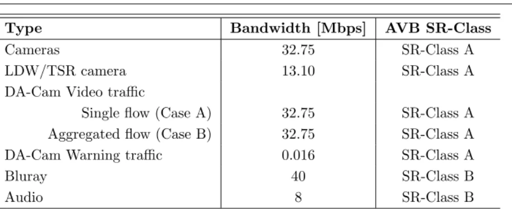
Table 4.1: Traffic Model and configured traffic/priority classes traffic and minimize the delay due to the acquisition and coding of the video frame. The car is also equipped with a multimedia in- car audio system allowing to listen to music at a very high quality and a HD-Video entertainment (e.g., a BluRay) system [41]. The BluRay video stream (encoded with MPEG4 High Definition standard) is di-rectly sent to the rear seats monitor (Rear Seat Entertainment, RSE), while the audio stream is coded with AAC (Advanced Audio Coding) and sent to the multimedia in-car audio system. Alternatively, the audio stream produced by a multimedia audio player can be sent to the in-car audio system instead of the BluRay audio stream. Table 4.1 shows the requirements for the traffic flows in our scenario.
Our performance metrics are:
• Latency, defined as the one-way frame end-to-end delay, i.e., the time from the source sending a packet to the destination receiving it.
• Jitter, defined as the absolute value of the difference between two consecutive inter-arrival times. The inter-arrival time is the
difference between the arrival times of two consecutive frames of the same stream. This jitter is calculated at the destination as in Eq. Equation 4.1
Jn= |(an− an−1) − (an−1− an−2)| (4.1) where n > 2, The arrival time an of the n-th Ethernet frame, and so the latency and the jitter, are measured at the application level.
The considered topology is a double-star where ADAS and enter-tainment traffic are transmitted on the same physical infrastructure. The network is shown in Figure 4.1 and consists of two directly con-nected switches. The first switch connects all the six cameras with the DA-Cam, the second one connects all the entertainment units and the Head Unit. The flows that traverse both the switches originate from the DA-Cam and go into the Head Unit. These flows consist of either a single view, i.e. a single flow (corresponding to case A in section 4.3), or multiple views aggregated in a single flow (corre-sponding to case B in section 4.3), in addition to navigation warnings present in both cases. The entertainment traffic traversing the second switch is the multimedia video traffic sent by the BlueRay player to be displayed on the RSE and the multimedia audio flow that the rel-evant audio player streams to the Digital Audio Amplifier. Table 4.1 summarizes the traffic flows we simulated in our scenario. It can be seen that the network operates under a high workload. As shown in Table 4.1,in the considered scenario all the ADAS-related traffic flows are mapped onto the AVB SR-Class A, while the entertainment traffic, i.e., the BluRay stream and multimedia audio, are mapped onto AVB
4.2. The simulation model 29
SR-Class B. This is because we assumed that all the traffic related to ADAS is more important than the entertainment traffic. According to the IEEE 802.1Qat standard [5] only 75% of the total bandwidth can be reserved to Class A and Class B, to leave room for best-effort traffic. As the standard [5] specifies that the percentage of bandwidth assigned can be sized according to the traffic needs, and given that there is no best-effort traffic in our scenario, here we assigned 90% of the Switch1 bandwidth to Class A and 5% to Class B, and 50% of the Switch2 bandwidth to Class A and the other 50% to Class B.
4.2
The simulation model
The network performance was evaluated using the OMNeT++ simu-lation tool and the INET-framework. The simulaton time was 600s. OMNeT++ [54] is a modular, component-based C++ simulation tool, primarily used for building network simulators. Components (mod-ules) of the simulation are programmed in C++, then assembled into larger components and models using a high-level language called NEt-work Description (NED) language. AVB simulator consists of two kind of modules:
• End-node (either talker or listener), each consisting of applica-tion, queue and mac submodule;
• Bridges, each consisting of relay unit, queue and mac submodule The end-node submodules were designed from stretch, while the bridge modules were obtained modifying the mac layer in the 802.1 bridge modules, included in the INET-framework [55], adding the SRP
Type Case A Case B
Avg Max Avg Max
Cameras 0.321 0.487 0.333 0.487
LDW/TSR camera 0.365 0.569 0.385 0.569 DA-Cam Video traffic 0.238 0.238 0.242 0.242 DA-Cam Warning traffic 0.098 0.170 0.105 0.180
Bluray 0.239 0.239 0.239 0.239
Audio 0.239 0.239 0.239 0.239
Table 4.2: Latency results, expressed in ms, for Ethernet frames in case A and case B
and the CBS functionalities. For each end-node is possible to define multiple flows to send and/or receive as well as the association between each queue in the outgoing port and a SR-Class. Configuration files are edited to change the traffic characteristic of each flow, including SR-Class, payload of each packet, period of the flow.
4.3
Results
In this section, latency and jitter results, measured for the ADAS video frames (Table 4.4 and Table 4.5) and for Ethernet data frames of all the traffic flows (Table 4.2 and Table 4.3), are discussed. As each video frame is split into 30 Ethernet frames for transmission, to measure the latency and jitter of the video frames we are interested in determining the latency of sequences of 30 Ethernet frames. We calculate the time between the instant when the first Ethernet frame of a sequence is sent and the instant when the last Ethernet frame of the sequence arrives at
4.3. Results 31
Type Case A Case B
Avg Max Avg Max
Cameras 1.45 54 6.02 81
LDW/TSR camera 555 881 555 960
DA-Cam Video traffic 0 0 0 0
DA-Cam Warning traffic 0.52 6.2 0.62 7.8
Bluray 0 0 0 0
Audio 0 0 0 0
Table 4.3: Jitter results, expressed in µs, for Ethernet frames in case A and case B
Type Case A Case B
Avg Max Avg Max
Cameras 32.68 32.68 32.43 32.43
LDW/TSR camera 16.50 16.50 16.51 16.51 DA-Cam Video traffic 32.41 32.41 32.43 32.43
Table 4.4: Latency results, expressed in ms, for ADAS video frames in case A and case B
Type Case A Case B
Avg Max Avg Max
Cameras 2.80 81 2.86 135
LDW/TSR camera 6.24 78 7.61 118 DA-Cam Video traffic 0 0 0 0
Table 4.5: Jitter results, expressed in ms, for ADAS video frames in case A and case B
Type Workload (Mbps) Throughput (Mbps) Case A Case B Case A Case B Switch 1 57.64 87.78 57.64 87.78 Switch 2 58.27 87.49 58.27 87.49
Table 4.6: Switch workload and throughput
destination. As far as latency measure is concerned, we determine the time elapsed between the arrival time of the first Ethernet frame of a video frame and the arrival time of the first Ethernet frame of the next video frame and obtain an interarrival time. The difference between two interarrival times is the jitter. Here we preliminary assessed that we do not have packet loss. This behaviour was obtained by a suitable configuration of the switch buffers size and thanks to the support provided by the AVB protocol. Moreover, the sum of all incoming traffic on different ports that is directed to the same outgoing port does not exceed the available bandwidth.
Table 4.6, that compares workload and throughput obtained by simulation, confirms our findings. Table 4.4 and Table 4.5 show the results for video frames. The maximum transmission time for a full video frame is 32.68 ms, the maximum experienced jitter is 135µs . The DA-Cam video frames have no jitter even though there is another parallel flow on the same link (i.e., navigation warnings) as both flows originate from the same unit and the navigation flow has a definitely lower bandwidth and service rate.
The null jitter is due to approximations in the simulator, that does not model the jitter of the hardware implementation. This is not a
4.3. Results 33
big issue, as here we want to show the effects of the protocol and not of the hardware. And, such a jitter is well below 1µs. For the Ethernet frames of the cameras (see Table 4.2 and 4.3) in Case A (i.e. a single flow from the DA-Cam to the HU) the jitter is due to the fact that several video streams are sent from the cameras to the same receiver (DA-Cam), and so the Ethernet frames are delayed in the relevant Switch1 outgoing queue. In Case B (aggregated flow) we see an increase of jitter due to the higher workload, but such an increase is not significant. The simulation results show that the AVB protocol performs well under the scenarios provided.
In particular, the latency experienced by the navigation warnings messages is way below the reaction time of a human driver (usually not lower than 0.5s [56]) and therefore fully compliant with the ADAS application constraints. The latency of BluRay traffic meets the re-quirements stated in [40]. The traffic from the cameras used for direct services experiences a latency which is always less than 33ms, while for this class of traffic the limit can be set to 45ms [40]. Since the LDW/TSR camera has a frame rate twice as the previous ones, its maximum allowed latency must be set to 45/2 = 22.5ms, but its la-tency is always less than 16.55ms (Table 4.4), so such a limit is met. The traffic originated by the DA-Cam ECU and addressed to the HU meets the same constraints as the Cameras traffic. Throughput and workload are almost the same in both the topologies and cases, thus confirming that there is no packet loss (see Table 4.6).
4.4
Conclusions
This preliminary performance assessment represented a first step of the investigation about IEEE AVB standard in automotive scenar-ios. According to the results here obtained, IEEE AVB proved to be a promising standard for being exploited in in-car networks. The work in [37] inspired comparative assessment between IEEE AVB and TTethernet that was realized in [38].
CHAPTER
FIVE
ASSESSMENTS OF IEEE AUDIO VIDEO
BRIDGING AND TIME-TRIGGERED
ETHERNET FOR IN-CAR COMMUNICATION
In this chapter a comparative assessment between IEEE Audio video Bridging and Time-Triggered Ethernet for in-car communication is described [38].
5.1
The considered scenario
In the scenario under study, shown in Table 5.1, different traffic types are considered:
• Advanced Driver Assistance Systems (ADASs). • CD Audio.
• DVD Video entertainment.
36 Ethernet for in-car communication
• Cross-domain traffic.
The ADASs here considered are based on a system composed by 6 cameras that generate video streams (one for each camera) and send them to a specialized Driver Assistance Electronic Control Unit, named DA-Cam, that processes them. According to the services they provide, in the considered scenario the cameras are split in two service groups [52]:
• Indirect services, aimed to improve road safety, that support the driver with navigation warnings derived from the processed video streams. The camera used for indirect services, i.e. Lane Departure Warning/Traffic Sign Recognition (LDW/TSR) is po-sitioned on the windshield close to the rear mirror. LDW is a mechanism devised to warn the driver when the car crosses a road lane marking or the edge of the road. TSR is a technology that enables a vehicle to recognize the traffic signs on the road. • Direct services, that support the driver with visual information in the form of views. In our scenario, there are five direct service cameras: Front, NightVision, Left, Right, Rear (see Figure 5.1). The flows processed by the DA-Cam are sent to the a Head Unit that is equipped with a monitor, installed on the cars dashboard, on which the received streams are displayed. The output flows pro-duced by the DA-Cam are new flows, either augmented with additional graphics to assist the driver or resulting from processing multiple cam-era flows to produce single views (e.g., Top view, Side view, etc.). A flow streamed to the Head Unit therefore consists of either a single view (as multiple views cannot be displayed at the same time on the
5.1. The considered scenario 37
Head Unit monitor because this is usually too small), or multiple views aggregated in a single flow in such a way that the Head Unit can se-lect and extract the needed view and display it on the monitor or, alternatively, send it to the RSE. As said before, the DA-Cam also produces navigation warnings that are displayed at the Head Unit monitor. In order to make the simulation scenario realistic, had to be decided how to model both the traffic generated by cameras and the streaming of the flows displayed on the Head Unit monitor, tak-ing into account both current practices and state of the art. Some previous works [42] considered MPEG-2 Transport Stream compres-sion (MPEG-2/TS) for both IP cameras and multimedia video. This can be considered as a conservative approach, as MPEG-2 traffic has been thoroughly analysed and modelled and hardware compression is available at reasonable costs. On the other hand, MPEG-2 has been recently replaced by more effective codecs based on the MPEG-4 stan-dard for a number of reasons. In most cases recent IP cameras for video surveillance adopt MPEG-4 SP (Simple Profile) for video coding as a trade-off between encoding/decoding complexity and bitrate/qual-ity combination. Compared to other standards for video compression, MPEG-4 SP requires a smaller bandwidth (a few Mbps in the scenario considered in [38]) while offering higher quality. Therefore, in [38] the MPEG-4 SP is the final choice. In the considered simulation scenario, the video frame rate generated by a camera is 30 frames per second (fps), while the video resolution selected for displaying the stream on the Head Unit monitor is 640 x 480 pixel. To model an increasing video traffic workload, two DA-Cam Aggregated flows is used. The first one, indicated in Table 5.1 as DA-Cam Aggregated (4-flows), starts at t=0s and stops at t=400s. The second one, named DA-Cam Aggregated
5-38 Ethernet for in-car communication
flows, models the workload increase corresponding to turning on in our scenario the fifth direct camera (i.e. the Night Vision one). It starts at t=400s and continues until the end of the simulation at t=600s. This way the behaviour of the network when the video traffic work-load increases over time could be assessed. The car is also equipped with a CD Audio and a DVD Video entertainment system. The DVD video stream, encoded with the MPEG-2 Program Stream standard (MPEG-2/PS), is directly sent to the rear seats monitor, while the au-dio stream is encoded with AC3 (Dolby Digital) and sent to the in-car digital audio amplifier. Alternatively, the audio stream produced by the audio-CD player can be sent to the in-car audio digital amplifier instead of the DVD audio stream. The features of the CD Audio and DVD video flows are shown in Table 5.1. The considered scenario also envisages cross-domain traffic, consisting of periodic data coming from the car control network which is gathered from a gateway device and injected in our network, directed to a Cross-Domain Processing Unit which extracts relevant data useful to the navigation and driver warn-ing functions. When a given condition is detected, which requires a driver warning, the Cross-Domain Processing Unit turns on the corre-sponding dashboard indicator. Here an increasing cross domain traffic is modelled using two flows. The first one, indicated as Cross-domain 1st flow in Table 5.1, starts at t=0s and stops at t=300s. The second one, named Cross-domain 2nd flow, is twice the first one. It starts at t=300s and continues until the end of the simulation at t=600s. This way the network behaviour could be assessed when the cross domain workload doubles over time. Table 5.1, in addition to the characteris-tics of our traffic flows, also shows their mapping on the traffic classes provided by AVB and TTE, respectively. The first column gives, for
5.1. The considered scenario 39
Type Bandwidth Activation AVB TTE
[Mbps] interval [s] SR-Class Priority
Cameras [5,15] 4x[0,600] + A RC (Prio 3)
1x[400,600]
LDW/TSR camera [2,6] [200,600] A RC (Prio 3)
DA-Cam single flow [1,3] [0,600] A RC (Prio 3)
DA-Cam
Aggregated (4-flows) [4,12] [0,400] A RC (Prio 3) Aggregated (5-flows) [5,15] [400,600] A RC (Prio 3)
DA-Cam warning 0.016 [200,600] A RC (Prio 2)
DVD player 10.08 [500,600] B RC (Prio 4)
Cd Audio Player 1.41 [0,600] B RC (Prio 4)
Cross Domain (1st flow) 0.0736 [0,300] A RC (Prio 1) Cross Domain (2nd flow) 0.147 [300,600] A RC (Prio 1)
Table 5.1: Characteristic of traffic model and configured traffic/pri-ority classes
each traffic type, the corresponding workload. For instance, [5, 15] for cameras means that the overall amount of video traffic generated by all the cameras varies between 5 and 15 Mbps. For camera flows, it is known that the workload is highly dependent on the specific video, i.e. on the scene being captured. As in [38] the main focus on evalu-ating the performance of the two addressed networks under high and very varying workload, the workload ranges typical of the adopted encoding is took as reference . Hence, the parameters of statistical distributions able to generate such workloads are derived. Table 5.1 also shows the activation interval of each traffic type. Every device in the network has in fact an activation interval that indicates when the device is switched-on and so the relevant traffic starts.
40 Ethernet for in-car communication
5.2
Simulation setup
The network performance was evaluated using the OMNeT++ simu-lation tool and the INET-Framework as described in 4.2. A protocol stack where the Application level is directly on top of Ethernet is sim-ulated, for both AVB and TTE. The protocol overhead is therefore 18 bytes for both TTE and AVB. For all the simulations, the duration is set to 600s. For each topology, two cases are investigated.
• Case A: the DA-CAM sends to the Head Unit a single flow (with a workload varying in the range [1,3] Mbps);
• Case B: DA-CAM sends to the Head Unit a flow resulting from the aggregation of flows from the Cameras that provide direct services (with a workload varying in the range [4,12] Mbps for the first 400s, and in the range [5,15] Mbps for the last 200 s of simulation).
Given the high variability of the video payload, traffic bursts are present in both scenarios. All the other traffic flows are the same in both cases and the relevant values are shown in Table 5.1.
AVB Setup In AVB simulation, all the traffic is mapped on the Stream Reservation (SR-AVB) classes. A priority value is associated with each SR-AVB class. For SR-AVB Class A the priority value is “3”, for SR-AVB Class B the priority value is “2”. As shown in Table 5.1, all the video flows from the cameras to the DA-Cam, the video flows and the navigation warnings from the DA-Cam to the Head Unit and cross-domain traffic are mapped onto Class A, while the entertainment traffic (i.e., the DVD stream and audio CD) are
5.2. Simulation setup 41
mapped onto SR- AVB Class B. The rationale behind this mapping is that AVB supports only two classes of time-sensitive traffic (i.e., Class A and Class B), and cameras video, DA-Cam video, navigation warnings and cross domain traffic are relevant to the driver safety. Those flows could have been split onto Class A and B but, doing so, entertainment traffic would be mapped either onto Class B, to the detriment of the safety-related flows in that class, that would have experienced interference from very bandwidth-greedy entertainment flows at the same priority level, or on best-effort traffic, without any guarantee on quality of service. With the chosen mapping the mix between safety-critical and non-safety critical flows is avoided, while some QoS guarantees also to the entertainment flows are provided.
This choice therefore reflects the different criticality of the flows from the user perspective (being safety-related traffic more critical than entertainment one). Bandwidth is reserved using the Stream Reservation Protocol (SRP) and the related signalling protocol, the Multiple Stream Registration Protocol (MSRP) for stream reserva-tions across the network. This protocol provides end stareserva-tions with the ability to reserve network resources that guarantee the transmission and reception of data streams across a network with the requested QoS. According to the IEEE 802.1Qat Standard [5] only 75% of the total bandwidth can be reserved to Class A and Class B, to leave room for best-effort traffic. Although in the considered scenario there is no best-effort traffic, the standard specifications are followed. The percentage for the reservable bandwidth is 40% for AVB SR Class A and 35% for AVB SR Class B. Each stream is identified from unique StreamID. The forwarding process provides one or more queues for a given switch port, each corresponding to a distinct traffic class. Each
42 Ethernet for in-car communication
traffic class is assigned a distinct priority level, so there is one queue for each priority level.
TTE Setup TTE supports three traffic classes. In the considered scenario the time-triggered traffic class is used for the Cross-domain traffic flows and the rate-constrained traffic class is used for the oth-ers. Four priority levels, with different queues, are used. Cross-domain traffic has the highest priority, i.e. prio 1, as it has a small payload and introduces a light workload, so we preferred to provide it with a preferential handling. For the same reason, the second priority level, i.e., level 2, is given to navigation warnings, while cameras and DA-Cam video have the third priority level, i.e. level 3. Finally, CD audio and DVD video streams have the fourth priority level, i.e. level 4. Strict Priority scheduling is used between the switch queues, FIFO within the same queue. The TT traffic is sent at regular time intervals. To support this traffic it is necessary to configure a complete off-line schedule. In the cycle time, i.e., the period after which the schedule is repeated, we define the slots in which every network device can send TT messages. In the offline planned slots no other traffic can be sent. TT traffic is actually generated at a well-defined time at the sending device and it must be received at a known time by the receiving device. A different receiving time of the frame could cause incorrect schedul-ing. For simulation purposes, an exact receiving time is not defined, but a very small temporal interval, called a receiving window, within which the reception of TT traffic is expected. This window is defined for every cycle time (which has a value of 5 ms) and is expressed in ticks (1 tick = 80 ns). The RC traffic is based on the concept of Virtual Link (VL), i.e., a logical unidirectional connection from one
5.3. Topologies 43
source end system to one or more destination end systems. The use of VL allows full-duplex communication channels on which multiple streams, each one identified by a CT-ID (Critical Traffic-Identifier), can be sent. Each VL is associated with a Bandwidth Allocation Gap (BAG), that is the minimum delay between two consecutive frames on the same VL. The application sending the message has to respect the constraint of the relevant configured BAG, otherwise the Ether-net frame will be considered not valid and will be dropped by the switch [3]. The model used for the TTE simulation was evaluated e validated using analytical methods and real-world measurements us-ing TTE hardware in [57]. The switches are characterized by a switch processing time of 8µs. The switch model used allows us to consider the propagation delay, that in our case has been fixed equal to 5 ns per meter and varies according to the length of the connections between the devices in the interval [0.3, 3.2] m.
5.3
Topologies
In [38] two different topologies are investigated. In the first one, called a single-star topology (Figure5.1), two separate switches are used, while in the second one, called a double- star topology (Figure5.2), there are two interconnected switches.
Single-star Topology In the single-star topology (Figure5.1), the first switch connects the ADAS cameras to the Driver Assistance Cam ECU (DA-Cam) unit. This choice, that differs from the approach in [41], where point-to-point connections are used between cameras and ADAS, is motivated by the need to reduce wiring complexity,
44 Ethernet for in-car communication
Figure 5.1: The single-star network topology
weight and costs (as explained in Chapter 1) replacing the current point-to-point Low-Voltage Differential Signalling (LVDS) wires with a switched network. The second switch connects the Head Unit with the DA-Cam, the Cross domain device with the Cross-domain Process-ing Unit (CPU), the DVD player with the Rear Seats Entertainment (RSE) system, and an audio player (CD-Audio) with the relevant dig-ital audio amplifier. The reason for two switches is to separate the flows originating from the cameras and directed to the DA-Cam from the rest of traffic, to avoid that entertainment and cross-domain traffic on the same switch could affect the performance of ADAS traffic. In the single-star topology, the DA-Cam is therefore a specialized ECU, equipped with two ports to be connected to two different switches, re-spectively. It produces new traffic flows (resulting from processing the ones received from the cameras and traversing the first switch), that are sent through the second switch to be displayed on the Head-Unit
5.3. Topologies 45
Figure 5.2: The double-star network topology
monitor. The second switch, in addition to the flows sent by the DA-Cam to the Head Unit, also handles the multimedia video traffic sent by the DVD player to be displayed at the Rear Seat Entertainment (RSE) system, the multimedia audio flow that the Audio-CD player streams to the Digital Audio amplifier and the cross-domain traffic that is processed by the Cross- domain Processing Unit (CPU).
Double-star Topology The second topology under study in [38], called a double-star topology, is shown in Figure5.2. Differently from the star topology, here the two switches are directly connected, so the DA-Cam is a one-port device. The flows that traverse both the switches originate from the DA- Cam and go to the Head Unit. Like in the single-star topology, these flows consist of either single views, or multiple views aggregated in a single flow, in addition to navigation warnings present in both cases. The cross-domain and entertainment
46 Ethernet for in-car communication
flows traversing the second switch in the double star topology are the same that traverse the second switch in the single star topology. The double star topology is investigated to assess the network performance when the traffic of the three domains, i.e. cross-domain, ADAS and entertainment, is transmitted on the same physical infrastructure, and the network operates under a high workload. In this case, in fact, the first switch is also traversed by the ADAS traffic generated by DA-Cam, so its workload is higher than in the single-star topology.
5.4
Results
The performance metrics considered for the comparative evaluations in [38] are the same described in section 4.1.
Latency Assessment - Single Star topology - Case A Table 5.2 shows the results for Ethernet AVB and TTE for Ethernet frames. Mean latency values for both protocols are in the same order of mag-nitude, although AVB has slightly higher values than TTE, with the exception of cameras and DVD flows. As far as maximum latency is concerned, TTE has slightly higher values for cameras, LDW/TSR and navigation flows, but lower values for the other traffic flows. For both protocols, a latency increase is observed, during simulation, whenever devices are dynamically activated. For example, when the LDW/TSR and NiVi cameras are added (at t=200s and t=400s, respectively), the latency increases about 80 µs for every device. LRD is high in cameras and LDW/TSR flows for both protocols, as several video streams at the same priority level are sent from the cameras to the same receiver (DA-Cam), and so the Ethernet frames are delayed in the relevant
5.4. Results 47
switch outgoing queue. The slight different LRD between the two protocols is due to the different frame scheduling in TTE (FIFO) and AVB (Credit-Based Shaping). The LRD values equal to 0 for Audio CD and DVD in TTE are because both these flows do not suffer from interference from other flows in the relevant queues. This behaviour is observed with TTE in all topologies and in all cases here addressed. For navigation flow in AVB, the LRD depends on the presence in the same switch output queue of large frames of other Class A traffic, i.e. DA-Cam flows. The maximum LRD for the DA-Cam flow shows that this flow is sometimes affected by the navigation warning traffic, that determines rare peaks starting from 200 s onwards. Average LRD values are instead very close to TTE results. The results prove that TTE benefits from using different priorities for navigation warnings and DA-Cam, while in AVB these traffic flows have the same priority level, as both flows are mapped onto Class A, so they mutually in-terfere. As explained in the AVB setup section, this is because AVB supports only two classes of time-sensitive traffic, Class A and Class B. Cross-domain traffic also obtains the best results in terms of latency and maximum latency deviation with TTE, thanks to the mapping onto the highest priority class (i.e., the time-triggered one).
Latency Assessment - Single Star topology - Case B In this scenario, instead of a single flow, DA-Cam streams to the Head Unit an aggregated video stream. The simulation results are shown in Ta-ble 5.3, where DA-Cam Aggregated (4-flows) and DA-Cam Aggregated (4-flows) are used to indicate the aggregated flow before and after the activation time of the night vision camera at time 400s (as indicated in Table 5.1), respectively. With TTE, there is almost no difference