ANTONIO CAGGIANO Meso-mechani cal analysi s of St eel Fi
ber Reinforced Cementitious Composites
Dottorato di Ricerca
in Ingegneria delle Strutture e del Recupero Edilizio ed Urbano
Università degli Studi di SalernoSede amministrativa
Doctorado
en Ciencias Exactas e Ingeniería
Universidad Nacional de TucumánSede Convenzionata per la Tesi in Co-Tutela Internazionale
Antonio Caggiano
MESO-MECHANICAL ANALYSIS OF
STEEL FIBER REINFORCED CEMENTITIOUS
UNIVERSITÀ DI SALERNO
DIPARTIMENTO DI INGEGNERIA CIVILE
Dottorato di Ricerca in Ingegneria delle Strutture e del
Recupero Edilizio ed Urbano
X Ciclo N.S. (2008-2011)
UNIVERSIDAD NACIONAL DE TUCUMAN (ARGENTINA)
FACULTAD DE CIENCIAS EXACTAS Y TECNOLOGÍA
Doctorado en Ciencias Exactas e Ingeniería
Tesi di Dottorato in Co-Tutela Internazionale
MESO-MECHANICAL ANALYSIS OF
STEEL FIBER REINFORCED CEMENTITIOUS
COMPOSITES
Antonio Caggiano
I Tutors
Il Coordinatore
Prof. José Guillermo Etse
Prof. Ciro Faella
Prof. Enzo Martinelli
To my family To my uncle Rosario Fabio
Acknowledgements
I would like to express my highest gratitude to Enzo and Guillermo, advisors of this thesis, for their time, effort and guidance during this work. They were (and are) like (academical) fathers. Really thanks!!! I would like to thank the wonderful people I met during this “fantastical journey”. Starting from all my colleagues of the University of Salerno, I would sincerely like to thank Carmen, Carmine, Gaetano, Jamil and Marco for the nice atmosphere at the laboratory which have contributed to create. My special thanks to Prof. Ciro Faella, Ph.D. coordinator and head of our group. Then, going to Argentina, my second country (in the last five years I lived more there than in Italy), I would like to deeply thank my colleagues Marianela, Paula, Sonia, Hernan, Javier, Juan and Victor for our nice and fruitful time spent at the Universities of Buenos Aires and Tucuman. Also to Eng. Raul Husni, Eng. Gregorio Pytlowany and Eng. Claudia Traiber of FIUBA for their continuous support. I extend my gratefulness to the authorities of UNISA and I also gratefully acknowledge the hospitality received in the Argentinean institutions of Buenos Aires (UBA) and Tucuman (UNT). I also acknowledges Officine Maccaferri S.p.A. for the financial support during the experimental research. Calcestruzzi Irpini S.p.A., General Admixtures S.p.A. and PreFabios S.r.l. are also acknowledged for having supplied materials for the experimental campaign. Further acknowledgments to Vittorio Cammarano and Diego Morrone for the collaboration in the experimental activity during their M.Sc. projects. At last, it is very difficult to express here, in a few lines, how much I appreciate the support of my family and the people close to me. At first, I sincerely thank my girlfriend (in the next weeks my wife) Sandra for her love, unconditional support, patience and encouragements during these last years. I would like to thank to my family, my parents Andreina and Domenico, my sister Caterina, my grandparents Rina, Pina and Giovanni, to Carmine for being always present. To my grandparent Antonio and my uncle Rosario present in my heart every day. I would like to express my highest thank to the family of my girlfriend, her parents Victoria and Miguel, Adrian and Florencia.
Abstract
The mechanical behavior of cement-based materials is greatly affected by crack propa-gation under general stress states. The presence of one or more dominant cracks in structural members modifies its response, possibly leading to brittle failure modes. The random dispersion of short steel fibers in cement materials is a new methodology used for enhancing the response in the post-cracking regime. The behavior of Fiber-Reinforced Cementitious Composite (FRCC), compared to conventional plain concrete, is characterized by several advantages, e.g., higher tensile and shear resistance, better post-cracking ductility, higher fracture energy, etc.
In this framework, this thesis deals with both the experimental investigation and com-putational modeling of the mechanical behavior of FRCC. A great part of the work is intended at reporting the formulation and validation of a novel constitutive model aimed at simulating the stress-cracking response of FRCC and considering most com-plex fracture occurrences in mixed-modes of failure.
Firstly, the results of an extensive experimental campaign, performed at the Laboratory of Materials testing and Structures (LMS) of the University of Salerno, is presented in which the possible influence of combining different fiber types on the resulting properties of Steel Fiber Reinforced Concrete (SFRC) is investigated. Particularly, the study concerns the four-point bending behavior of pre-notched SFRC beams where the influence of the amount of fibers and types on the first-crack strength and the whole post-cracking behavior is analyzed.
After this, an innovative approach for reproducing the fiber effects on the cracking phenomena of the concrete/mortar matrix is proposed. The well-known discrete crack approach based on zero-thickness interface elements is used to model the interaction between fibers and mortar as well as its degradation during fracture processes under mode I, II and/or mixed ones. The matrix degradation is modeled by means of a fracture energy-based softening law formulated in the framework of the flow theory of plasticity. Then, two fundamental aspects of the fiber-mortar interaction are considered in the model, i.e., the bond behavior of fibers bridging the crack opening and the dowel effect derived by possible relative transverse displacements of the two faces of the crack. The
inclusion of fibers and the above two effects are taken into account by means of the well-known “Mixture Theory”. Particular emphasis and importance is dedicated to the description and modeling of the overall debonding behavior of fibers embedded in cementitious matrices. Actually, the adhesive interaction between fibers in concrete matrix is of key importance in controlling the post-cracking response of FRCC. A unified formulation for simulating the overall bond behavior of fibers embedded in cementi-tious matrices is also presented. The proposed unified formulation is intended as a key element to be possibly employed in numerical models aimed at explicitly simulating the mechanical behavior of FRCC by taking into account the discrete nature of such materials and the contributions of the various constituents within the framework of the so-called meso-mechanical approach.
The predictive capabilities of the aforementioned discontinuous approach for failure analyses of fiber reinforced cementitious composite are evaluated at different levels of observation. Particularly, the discrete crack formulation is employed and validated to simulate the fracture behavior of FRCC at constitutive, mesoscopic and macroscopic levels of observations. Several numerical results are performed to demonstrate if such proposal, based on the non-linear interface formulation, is capable to lead realistic predictions of failure processes of FRCC under different load scenarios and considering a wide spectrum of fiber contents and types. It is also analyzed if the proposed formu-lation is able to capture the significant influence of the fiber content on the maximum strength and post-peak ductility in mode I, II and mixed ones showing the capability of the cracking formulation to capture the complex interaction mechanisms between fibers and matrix.
Furthermore, a simpler stress-crack opening model based on a hinge-crack approach, already available in the scientific literature, is proposed while the experimental results reported in this thesis are taken as reference for its validation. The model represents a reformulation of a fictitious crack model and is based on fracture mechanics concepts where the stress-crack opening relationship is accounted in a similar way obtainable by considering the pure “mode I” case of the discontinuous proposal formulated in general sense for mixed-modes of fracture. A closed-form solution for the stress-crack opening law with the explicit consideration of the fiber actions is considered for such a formulation. The model predictions, compared with the experimental measures, are performed to demonstrate the soundness of the model to reproduce the mechanical response of SFRC members in terms of Force-Crack Tip Opening Displacement (C T OD) curves.
At last, both plain concrete and FRCC are analyzed and modeled by means of a novel microplane-based plasticity formulation. A continuum (smeared-crack) formulation, based on the non-linear microplane theory combined with the well-known “Mixture
Abstract Theory”, is considered for describing the fiber effects on the failure behavior of FRCC. The constitutive formulation, failure analyses and the interactions between cementi-tious matrix and steel fibers are similarly approached as outlined for the discontinuous proposal. The capabilities of the microplane model to capture the significant enhance-ment in the post-cracking behavior of FRCC, with particular emphasis on the fracture and post-peak strengths, are finally evaluated by considering some experimental data available in scientific literature.
Contents
Acknowledgements iii
Abstract v
Table of contents xii
List of figures xix
List of tables xxi
1 Introduction 1
1.1 Scientific framework and general overview . . . 1
1.1.1 Fiber types: material and geometry . . . 2
1.1.2 Mechanical behavior and characterization . . . 3
1.2 Theoretical proposals for concrete-like materials . . . 5
1.2.1 Observation scale and modeling . . . 6
1.2.2 Crack modeling strategies and approaches . . . 10
1.3 Codes and Standards for Fiber-Reinforced Cementitious Composites . . 15
1.4 Motivation . . . 23
1.5 Objectives and activities of the thesis . . . 24
1.6 Thesis structure and main contents . . . 26
2 Experimental characterization of steel fiber notched concrete beams 29 2.1 Flexural tests for obtaining residual strengths . . . 29
2.2 Experimental campaign . . . 30 2.2.1 Materials . . . 31 2.2.2 Test method . . . 32 2.2.3 Test programme. . . 33 2.3 Experimental results . . . 35 2.3.1 Compression . . . 35
2.4 Closing remarks . . . 42
3 Zero-thickness interface model for FRCC 43 3.1 Interface constitutive model for FRCC. . . 44
3.2 Outline of the Mixture Theory. . . 44
3.2.1 Composite material model . . . 44
3.2.2 Constitutive models of each single phase . . . 48
3.3 Fracture energy-based model for plain mortar/concrete interface . . . . 50
3.3.1 Single internal state variable . . . 53
3.3.2 Evolution laws of the fracture surface . . . 53
3.3.3 An overview of the interface model for plain concrete/mortar . . 55
3.4 One-dimensional bond-slip model for fibers . . . 56
3.4.1 Pull-out analysis of a single fiber . . . 58
3.4.2 Verification of the pull-out model . . . 60
3.5 Dowel effect of steel fibers crossing cracks in cementitious matrix . . . . 61
3.5.1 Dowel stiffness . . . 62
3.5.2 Dowel strength . . . 64
3.6 Closing remarks . . . 64
4 Bond behavior of fibers in cementitious materials: a unified formulation 67 4.1 Importance of the bond-slip modeling . . . 67
4.2 Bond behavior of fibers in concrete matrix: Basic assumptions . . . 69
4.2.1 Behavior of steel fibers . . . 69
4.2.2 Interface bond-slip models . . . 70
4.3 Elasto-plastic joint/interface model with isotropic linear softening . . . 71
4.3.1 Basic assumptions and closed-form solution. . . 72
4.3.2 Full-range bond-slip behavior . . . 75
4.4 Fracture energy-based interface model . . . 80
4.4.1 Incremental plastic multiplier . . . 80
4.4.2 Algorithmic tangential operator . . . 82
4.4.3 Shear-slip test . . . 83
4.5 Numerical results and experimental validation . . . 84
4.5.1 Effect of matrix strength and fiber anchorage . . . 84
4.5.2 Fiber anchorage and diameter effects . . . 87
4.6 Closing remarks . . . 90
5 Model performance and numerical predictions 93 5.1 Numerical analyses . . . 93
Contents
5.1.2 SFRC failure behavior under mixed-modes of fracture . . . 97
5.1.3 Parametric study . . . 100
5.2 Cracking analysis of the proposed interface model for FRCC . . . 104
5.2.1 Post-cracking behavior. . . 105
5.2.2 Failure performance and cracking indicators for mixed fracture modes . . . 106
5.3 Closing remarks . . . 112
6 Structural scale failure analysis of FRCC 115 6.1 Influence of the interface positions at structural scale . . . 115
6.2 Macroscopic and mesoscopic FE analysis with FRC interfaces: three-point bending tests . . . 121
6.2.1 Notched beams under three-point bending at macroscale. . . 121
6.2.2 FE analysis of SFRC at mesoscopic scale . . . 123
6.3 Meso- and macroscopic FE Analysis with FRC Interfaces: Compressive Test131 6.3.1 Compressive Test at mesoscopic level . . . 131
6.3.2 Compressive test at macroscopic scale . . . 134
6.4 Macroscopic FE analysis of shear test on SFRC. . . 137
6.5 Closing remarks . . . 139
7 Cracked hinge numerical model for fiber-reinforced concrete 141 7.1 Basic assumptions . . . 141
7.2 Bond-slip bridging of fibers on concrete cracks . . . 147
7.3 Dowel action of fibers crossing the concrete cracks . . . 147
7.4 Numerical predictions . . . 148
7.5 Closing remarks . . . 151
8 Elasto-plastic microplane formulation for FRCC 153 8.1 Introduction . . . 154
8.2 Basic assumptions of the microplane-based material model. . . 155
8.2.1 Kinematic assumptions . . . 155
8.2.2 Homogenization between macro- and microplane stress space. . 156
8.3 Composite constitutive formulation for FRCC . . . 156
8.4 Fracture energy-based cracking microplane model for plain concrete/-mortar . . . 158
8.4.1 Microplane elasto-plasticity constitutive formulation . . . 158
8.4.2 Post-cracking behavior. . . 159
8.5 Crack-bridging effect of fibers. . . 164
8.6.1 Tensile tests . . . 165
8.6.2 Shear test results: influence of the integration approximation over the unit hemisphere . . . 169
8.7 Closing remarks . . . 172
9 Conclusions 173 9.1 Experimental activity. . . 173
9.2 Zero-thickness interface model formulation . . . 174
9.3 Fiber bond-slip characterization . . . 175
9.4 Hinge-crack model . . . 177
9.5 Microplane proposal . . . 177
9.6 Future research lines . . . 178
List of Figures
1.1 Steel fiber types proposed by ACI-544.1-96 [1996]. . . 3
1.2 FRC composites based on the classification proposed by Naaman and Reinhardt [2006]. . . 5
1.3 Concrete materials under different scales of observation: (a) macroscale contin-uum, (b) 2-D mesoscale concrete analysis [Kim and Al-Rub, 2011], (c) modeling the hydration of cements at microscale [Bishnoi and Scrivener, 2009] and (d) simulations by means of electrophilic and nucleophilic attack at a nanoscale standpoint [Puertas et al., 2011]. . . 7
1.4 Numerical specimens based on the Element-Free Galerkin method by Belytschko et al. [1995] for near-tip crack problems. . . 11
1.5 Meso-mechanical simulation by means of the beam lattice model [Lilliu and van Mier, 2003]: (a) geometry, (b) definition of matrix, interface and aggregates, (c) crack pattern simulations. . . 12
1.6 Elemental (E-FEM) and eXtended (X-FEM) enrichment approaches [Oliver et al., 2006]. . . 13
1.7 Unnotched specimens in tension of various sizes with randomly generated particles by Bazant et al. [1990]. . . 13
1.8 FE mesoscale discretization [Lopez et al., 2008a,b]: (a) 6 x 6 aggregate-arrangement, (b) matrix, (c) coarse aggregates and (d) interfaces. . . 14
1.9 Constitutive σ − ² laws for the tensile behavior of FRCC: a) rectangular and b)
bilinear shapes [CNR-DT-204, 2006], c) trilinear law [RILEM-TC162-TDF, 2003] and d) multilinear rules [fib Model-Code, 2010a]. . . 16
1.10Experimental set-up and geometry details of the notched beams under three-point bending test [fib Model-Code, 2010a]. . . 18
1.11Typical curve of the nominal stress versus C MOD for FRC [EN-14651, 2005]. . 19
1.12Post-cracking constitutive laws for ULS states [fib Model-Code, 2010a]. . . 21
1.132D meso-structure geometry: (a) Delaunay triangulation/Voronoi tessellation [Idiart, 2009], (b) FRCC meso-probe, (c) coarse aggregates and (d) position of the interface elements. . . 26
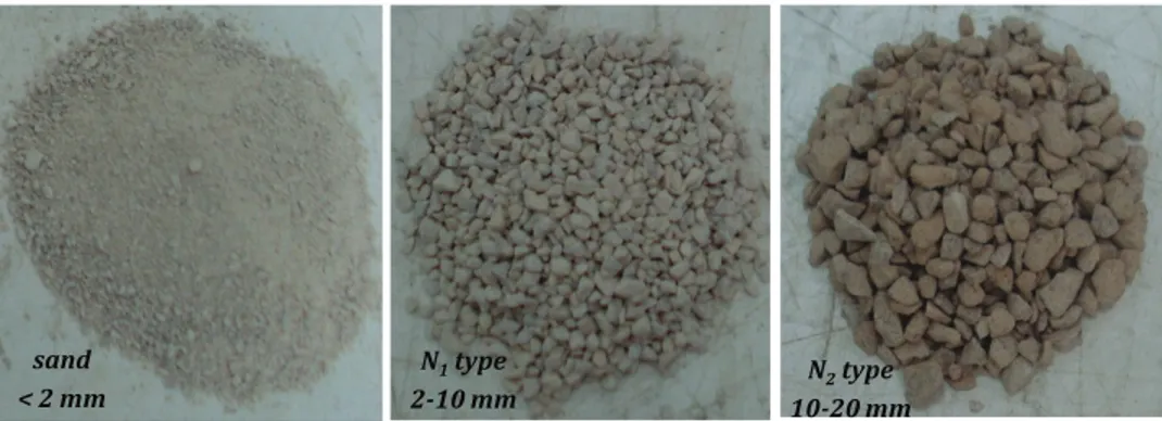
2.1 Fine and coarse aggregates employed in the experimental campaign. . . 31
2.2 Grain size distribution of the “REF” mixture. . . 32
2.3 Fiber types: FS7 (short fiber) and FF3 (long fiber). . . 32
2.4 Four-point bending test: (a) experimental set-up and (b) geometry of the notched beams. . . 33
2.5 Four-point bending test: (a) load-cell and (b) crack opening transducers. . . . 33
2.6 Underwater curing of specimens during 28 days at constant temperature of approximately 22oC . . . . 34
2.7 SFRC samples to be tested in compression. . . 35
2.8 Compressive stress - strain curves of “white” concretes and SFRCs having ρf = 0.5% and ρf = 1.0% of fiber volume contents. . . 36
2.9 Cube compressive strengths of the SFRC samples [EN-12390-3, 2009]. . . 37
2.10Vertical force - C T ODm curves: black lines refer to specimens with 1.0% of fiber volume content while grey lines indicate the 0.5% of fiber fraction. . . 38
2.11First crack strength, fl f, and the equivalent crack ones, feq(0−0.6)and feq(0.6−3.0) [UNI-11039-2, 2003]. The vertical segments quantify the min-max range observed for each concrete mixture. . . . 39
2.12Energy absorption measures U1and U2according to UNI-11039-2 [2003]. The vertical segments quantify the min-max range observed for each concrete mixture. 40 2.13Indices of the ductility according to UNI-11039-2 [2003]. The vertical segments quantify the min-max range observed for each concrete mixture. . . . 41
2.14Classifications based on the first crack resistances and the ductility indices by UNI-11039-1 [2003] code. . . 41
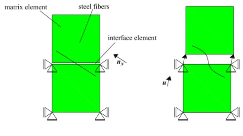
3.1 Main assumptions of fiber-reinforced cementitious composite in the framework of the well-known “Mixture Theory” [Trusdell and Toupin, 1960]. . . 45
3.2 Mixture components of the FRCC continuum material. . . 46
3.3 Schematic configuration of an interface element crossed by one fiber. . . 47
3.4 Fiber effects on the plane of the zero-thickness interface. . . 48
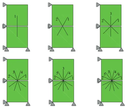
3.5 Considered fibers crossing the interface: as example the cases of 1, 2, 3, 4, 5 and 6 reinforcements are presented. . . 49
3.6 Failure hyperbola by Carol et al. [1997], Mohr-Coulomb surface, plastic potential and the modified flow rule according to Eq. (3.19) of the interface model. . . . 51
3.7 Evolution law of the interface fracture parameters. . . 53
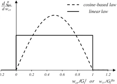
3.8 Cosine-based vs. linear law related to the ratio between the work spent wcrand the available fracture energies GIf or GI I af . . . 54
3.9 Comparison of the derivates between the cosine-based law against the linear rule. . . 55
List of Figures
3.10(a) Uniaxial model of fiber bond-slip and (b) serial model for the axial/debonding
behavior. . . 57
3.11Pull-out of a single fiber. . . 59
3.12Pull-out tests (discontinuous lines) by Lim et al. [1987] on straight and hooked-end steel fibers vs. numerical results (continuous lines). . . 61
3.13Dowel effect based on the well-known Winkler beam theory. . . 63
4.1 Considered scheme of fiber under pull-out loading. . . 70
4.2 Bond-slip plasticity model with linear softening. . . 72
4.3 Schematic components of pull-out analysis for the analytical solution. . . 73
4.4 Schematic representation of the overall debonding process. . . 78
4.5 Typical analytical curves of the applied load Pivs. debonding displacement si in case of short and long anchorage condition. . . 79
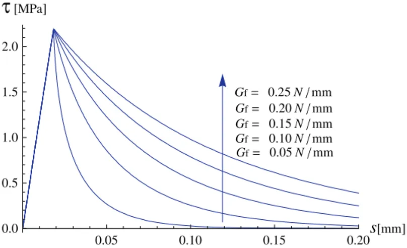
4.6 Bond-slip model: shear stress (τ) vs. relative slip (s) for different values of fracture energy Gf. . . 84
4.7 Fracture energy-based model results (continuous lines) vs. experimental data (square, circular and rhomboidal points) by Shannag et al. [1997]. . . 85
4.8 (a) Analytical and (b) FEM results (continuous lines) for bilinear τ − s against the experimental data (square, circular and rhomboidal points) by Shannag et al. [1997]. . . 85
4.9 Fracture energy-based model results (continuous lines) vs. experimental data (square, circular and rhomboidal points) by Shannag et al. [1997]. . . 86
4.10(a) Analytical and (b) FEM results (continuous lines) for bilinear τ − s vs. the experimental data (square, circular and rhomboidal points) by Shannag et al. [1997]. . . 86
4.11Numerical prediction (continuous line) vs. experimental data (points) [Ban-holzer et al., 2006]: fiber diameter of 0.8mm and anchorage of 22.1mm. . . . . 87
4.12Numerical prediction (continuous line) vs. experimental data (points) [Ban-holzer et al., 2006]: fiber diameter of 1.5mm and anchorage of 27.1mm. . . . . 88
4.13Numerical prediction (continuous line) vs. experimental data (points) [Ban-holzer et al., 2006]: fiber diameter of 2.0mm and anchorage of 35.0mm. . . . . 88
4.14Pull-out simulation for a steel fiber diameter of 0.8mm and an embedded length of 22.1mm by Banholzer et al. [2006]: (a) load-slip curve Pi− si, (b) interface shear stress distributions τ − z and (c) axial strain distributions εs− z. . . . 89
4.15Pull-out simulation for a steel fiber diameter of 1.5mm and an embedded length of 27.1mm by Banholzer et al. [2006]: (a) load-slip curve Pi− si, (b) interface shear stress distributions τ − z and (c) axial strain distributions εs− z. . . . 90
4.16Pull-out simulation for a steel fiber diameter of 2.0mm and an embedded length of 35.0mm by Banholzer et al. [2006]: (a) load-slip curve Pi− si, (b) interface
shear stress distributions τ − z and (c) axial strain distributions εs− z. . . . 91
5.1 Test set-up of tensile tests performed by Li et al. [1998] and the corresponding analysis model. . . 94
5.2 Experimental data [Li et al., 1998] and numerical simulation for SFRC with Dramix fibers. . . . 96
5.3 Experimental data [Li et al., 1998] and numerical simulation for SFRC with Harex fibers. . . 96
5.4 Test set-up by Hassanzadeh [1990]: (a) concrete sample, (b) tensile state and (c) mixed fracture displacements. . . 97
5.5 Boundary conditions and FE-discretization with one single interface crossed by short fibers for Hassanzadeh [1990] tests on SFRC panels. . . 98
5.6 Normal stress vs. relative vertical displacement performed with different amount of fibers and θ = 90o. . . 98
5.7 Hassanzadeh [1990] tests with different number of fibers and θ = 75o: a) normal
stress vs. relative normal displacement and b) shear stress vs. relative tangential displacement. . . 99
5.8 Hassanzadeh [1990] tests with different number of fibers and θ = 60o: a) normal
stress vs. relative normal displacement and b) shear stress vs. relative tangential displacement. . . 99
5.9 Hassanzadeh [1990] tests with different number of fibers and θ = 30o: a) normal
stress vs. relative normal displacement and b) shear stress vs. relative tangential displacement. . . 100
5.10Comparison between numerical predictions and experimental results by Li and Li [2001]: SFRC with “Dramix type II” fibers. . . 102
5.11Comparison between numerical predictions and experimental results by Li and Li [2001]: SFRC with “Dramix type I” fibers. . . 102
5.12Comparison between numerical predictions of the test by Li and Li [2001] on SFRC with “Dramix type II” fibers: (a) full debonding vs. 50% of the debonding strength and (b) full fracture energy, GI
f, vs. 50% of GIf. . . 103
5.13(a) Experimental test by Hassanzadeh [1990] and numerical predictions for SFRC with “Dramix type I” fibers with ρf = 5.0% and (b) effect of the dowel strength
on the stress-opening displacements in mixed-modes of fracture. . . 104
5.14ρand θ angles defined in the interface stress space. . . . 106
List of Figures
5.16Post-cracking analysis at peak stress for different concrete types: plain concrete and SFRC with “Dramix type I” fibers having fiber contents of 3.0% and 6.0%. . 108
5.17Polar plots of post-cracking analysis of TS5 and TS6 for different concrete types: plain concrete and SFRC with “Dramix type I” fibers having fiber contents of 3.0% and 6.0%. . . 109
5.18Polar plots of post-cracking analysis of TS3 and TS4 for different concrete types: plain concrete and SFRC with “Dramix type I” fibers having fiber contents of 3.0% and 6.0%. . . 110
5.19Polar plots of post-cracking analysis of TS2 and UT for different concrete types: plain concrete and SFRC with “Dramix type I” fibers having fiber contents of 3.0% and 6.0%. . . 111
6.1 FE discretization including the cases of: (a) one, (b) four and (c) eight interfaces. 116
6.2 Boundary conditions of (a) uniaxial tensile and (b) compressive cases, (c) shear with unconstrained dilatancy and (d) shear with constrained dilatancy. . . 116
6.3 Vertical load-displacement behavior of plain concrete and SFRCs under tension (left side) and crack paths (right side). . . 117
6.4 Vertical load-displacement behavior of plain concrete and SFRCs under com-pression (left side) and crack paths (right side). . . 118
6.5 Lateral load-displacement behavior of plain concrete and SFRCs in direct shear with free dilatancy in the vertical direction (left side) and crack paths (right side).119
6.6 Lateral load-displacement behavior of plain concrete and SFRCs in direct shear with blocked dilatancy in the vertical direction (left side) and crack paths (right side). . . 120
6.7 Three-point bending test discretization on a notched beam for discrete failure analyses. . . 122
6.8 Numerical results vs. experimental data by Rots et al. [1985] on a three-point beam. . . 122
6.9 Failure configuration in terms of (a) vertical displacement mesh informations and (b) work spent to available energy ratio of wcr/GIf. . . 123
6.10FE discretization including Fiber Reinforced concrete and mortar, coarse aggre-gates and interfaces. . . 124
6.11(a) Initial regular 2D distribution, (b) randomly perturbed positions, (c) super-position of the points and (d) Voronoi/Delaunay tessellation. . . 125
6.12Geometry and boundary conditions of the three-point bending problem of fiber reinforced concrete beam according to Carpinteri and Brighenti [2010]. . . 126
6.13Load-deflection behavior of three-point beam with central notch: numerical simulation vs. experimental results by Carpinteri and Brighenti [2010]. . . 127
6.14Crack paths of plain concrete and SFRC under three-point bending with centrical notch by Carpinteri and Brighenti [2010]. . . 128
6.15Load-deflection behavior of plain concrete and SFRC three point beams with eccentrical notch: comparison between numerical and experimental results [Carpinteri and Brighenti, 2010]. . . 129
6.16Crack paths of plain concrete and SFRC three-point beams with eccentrical notch at 0.25l (distance between the mid-length of the beam and the notch position) by Carpinteri and Brighenti [2010]. . . 130
6.172-D FE discretization for concrete specimens with 6 ×6 aggregates: (a) geometry, (b) continuum elements and (c) interfaces. . . 131
6.18Results in uniaxial compression. . . 132
6.19Sequence of micro- and macrocracks at various loading stages. . . 133
6.202-D FE discretization for concrete specimens at macro-level: (a) continuum elements and (b) interfaces. . . 134
6.21Results in uniaxial compression. . . 135
6.22Sequence of micro- and macrocracks at various loading stages. . . 135
6.23Geometry, boundary conditions and discretization of the shear tests on plain and steel reinforced mortar specimens. . . 137
6.24Numerical simulations dealing with the lateral load vs. lateral displacements of the shear tests. . . 138
6.25Final pattern of the (a) plain mortar and (b) steel fiber reinforced mortar (ρf =
6.0% fiber content) specimens after the numerical analyses with the shear box. 138
7.1 Geometrical description of the analyzed four-point bending scheme. . . 142
7.2 Stress distributions and fiber actions during the crack evolution. . . 143
7.3 The three orientation zones for the square cross section beam: b × h × l (base × height × length) having l ≥ b and l ≥ h. . . . 144
7.4 Cracked hinge: (a) stress-crack opening displacement of plain concrete and (b) main geometrical assumption under deformation. . . 145
7.5 Load-C T ODm numerical predictions against the experimental data on SFRC L100-type by Caggiano et al. [2012a]. . . 148
7.6 Load-C T ODm numerical predictions against the experimental data on SFRC L75-type by Caggiano et al. [2012a]. . . 149
7.7 Load-C T ODm numerical predictions against the experimental data on SFRC LS50-type by Caggiano et al. [2012a]. . . 149
7.8 Load-C T ODm numerical predictions against the experimental data on SFRC S75-type by Caggiano et al. [2012a]. . . 150
List of Figures
7.9 Load-C T ODm numerical predictions against the experimental data on SFRC S100-type by Caggiano et al. [2012a]. . . 150
8.1 (a) Concrete specimen, (b) continuum discretization scale, (c) 4-node contin-uum FE and (d) spherical microplane region at gauss-point with a generalized normal direction. . . 155
8.2 Strain and stress components at the microplane level. . . 156
8.3 Maximum strength criteria and plastic flow rules. . . 160
8.4 S[ξ#] scaling function of the microplane model in terms of the ξ#parameter,
where the # symbol = χmi c,cmi c, tan(αmi c) or σ
N ,C AP. . . 162
8.5 ξ#functions, with # = χmi c,cmi c, tan(αmi c) or σN ,C AP, depending on the work
spent-to-fracture energy ratio, wcr/GIf or wcr/GI I af . . . 163
8.6 Yielding criteria at different ratios between work spent values and fracture en-ergies: µ wcr GI f , wcr GI I a f ¶ = (0.0,0.0), (0.2,0.1), (0.4,0.2), (0.6,0.3), (0.8,0.4), (1.0,0.5), (1.0,0.6), (1.0,0.8) (from the biggest size up to smallest one). . . 163
8.7 Microplane strain activating the fiber bridging effects. . . 165
8.8 Load configurations and restraint conditions for uniaxial tension and simple shear. . . 166
8.9 Comparison between the numerical predictions and the experimental results (dotted curves) by Li and Li [2001] of SFRCs with “Dramix type I” and “type II”. 167
8.10Interface-based simulations vs. microplane ones under tensile load cases. . . . 169
8.11Lateral shear load - displacement by considering several integration points (varying from 2 to 25) and fiber percentages. . . 170
8.12Lateral shear load - displacement comparisons when several microplane num-bers and fiber contents are considered. . . 171
List of Tables
2.1 Mix design per cubic meter of the reference concrete. . . 31
2.2 Geometric and mechanical properties. . . 32
2.3 Key proprieties of the concrete mixtures. . . 34
2.4 Densities and cube compressive strengths measured in each mixture. . . 35
3.1 Overview of the interface model for Plain Concrete/Mortar. . . 55
3.2 Bond response of the fiber-concrete joint depending on the slip s[x] developed throughout the embedment length. . . 60
3.3 Model parameters for the pull-out tests by Lim et al. [1987]. . . 61
4.1 Interface bond-slip models. . . 71
4.2 Analytical bond-slip model of the bilinear τ − s relationship. . . . 76
4.3 Model parameters according to the tests by Shannag et al. [1997]. . . 86
5.1 Fiber types employed in the experimental tests by Li and Li [2001]. . . 101
6.1 Material parameters based on the experimental data by Rots et al. [1985]. . . . 121
6.2 Material parameters employed in the mesoscale analyses. . . 128
1
Introduction
1.1 Scientific framework and general overview
In the last century, concrete has become the most widely used construction material and, then, a great part of the existing built stock, as well as the majority of infrastructures currently under construction are made of Reinforced Concrete (RC). In spite of the wide variability of the relevant physical and mechanical properties of cohesive-frictional media, cement-based materials like concretes are characterized by low strength and brittle response in low confinement and tensile stress states. These deficiencies can be mitigated by randomly adding short reinforcements into the cementitious mortar [Gettu,2008].
The development of innovative cementitious materials, going to the direction of High Performance Concretes (HPCs) in general sense, represents a new field of interest of the Material Science and Structural Engineering. In this sense, Fiber-Reinforced Cementitious Composite (FRCC), obtained by randomly mixing short fibers (made out of steel, plastic, natural materials, recycled reinforcements, etc.) into conventional cementitious materials, is a structural material characterized by a significant residual tensile strength in post-cracking regime in comparison to plain concrete and enhanced capacity to absorb strain energy due to fiber bridging mechanisms across the opening cracks [Brandt,2008,di Prisco et al.,2009,Nguyen et al.,2010].
Fiber-Reinforced Cementitious Composites (FRCCs) may result in a less brittle and possible quasi-ductile behavior, even in the case of tensile loading, and exhibit strain-hardening processes with multiple cracks and relatively large energy absorption prior to failure. Composites with these relevant features take the name of High Performance Fiber-Reinforced Cementitious Composites (HPFRCCs) [Naaman and Reinhardt,2006].
1.1.1 Fiber types: material and geometry
Fiber Reinforced Cementitious Composite (FRCC) is a concrete made of hydraulic ce-ment, aggregates and discrete reinforcing fibers. There are several fiber types employed for engineering applications and classified according to their material. Particularly the following categories can be listed:
• steel fibers of different shapes and dimensions; • glass fibers;
• fibers of synthetic materials such as polypropylene, polyethylene and polyolefin, polyvinyl alcohol (PVA);
• recycled ones (PET, from waste tires); • natural fibers.
Referring to its geometry, fiber is defined as “short” and “discrete”. One of the proprieties which characterizes its geometry is represented by the “aspect ratio”: it represents the ratio between the fiber length and the equivalent diameter. The latter is calculated as the diameter of a circle having an area equal to the cross-section of the considered fiber.
The most important short reinforcements, for structural concrete, are surely repre-sented by the steel fibers. The length and diameter of such fibers, used for FRCC, do typically not exceed the 75mm and 1mm, respectively. As example the Figure1.1
outlines various steel fiber geometries characterized by different shapes for improving the fiber-matrix bond and aimed at increasing the efficiency of the bridging effect of fibers.
Recent researches on Fiber-Reinforced Concrete (FRC) also address to the possible use of mixed fibers of different material and/or geometry which can, in principle, play a synergistic role in enhancing flexural and post-cracking response of FRC mem-bers. This kind of fiber-reinforced cement-based composites are known as Hybrid FRC (HyFRC). Experimental tests aimed at investigating the HyFRC failure behavior in direct tension have been performed, among others, bySorelli et al.[2005] andPark et al.[2012]. The mechanical behavior measured by means of indirect tensile tests have been proposed on Hy-Polypropylene FRC [Hsie et al.,2008], Hy-Steel FRC [Banthia and Sappakittipakorn,2007,Kim et al.,2011] or combining several material fibers: i.e., Car-bon/Steel/Polypropylene FRC [Yao et al.,2003] or Steel/Palm/Synthetic FRC [Dawood
1.1. Scientific framework and general overview
Figure 1.1:Steel fiber types proposed byACI-544.1-96[1996].
and Ramli,2011,2012]. The experimental results on contoured double cantilever beam specimens with steel and polypropylene FRC have been discussed byBanthia and Nandakumar[2003]. Other relevant contributions regarding HyFRC with lightweight aggregates [Libre et al.,2011], high-volume coarse fly ash [Sahmaran and Yaman,2007], RC beams with mixed fibers [Ding et al.,2010], HyFRC exposed to high temperatures [Chen and Liu,2004,Ding et al.,2012] or self compacting HyFRC [Ding et al.,2009,
Dawood and Ramli,2010,Akcay and Tasdemir,2012] have also been proposed within the scientific community.
1.1.2 Mechanical behavior and characterization
Since fiber bridging mechanisms mainly take place under cracked regime of the con-crete matrix, the mechanical behavior of uncracked members is rather influenced by
the fiber addition. This represents the main reason that the first crack tensile strength of FRCC is mainly related to the matrix strength and very low influenced by the fiber contents.
Contrarily, the post-cracking tensile residual strengths are the most influenced me-chanical properties due to the fiber bridging mechanisms. These quantities can be experimental obtained by means of direct or indirect tensile tests. Due to the well-known difficulties in realizing experimental studies throughout direct uniaxial tests in tension, the adoption of bending systems in pre-notched beams is the most common method (as largely used in the most widespread international standards and codes) for the FRCC characterization. However, although the bending response involves only mode I of failure, is quite different from the uniaxial tension: for example a FRCC, with a strain-softening response in tension, could behave in strain-hardening manner in bending. The possible classification of FRCC, based on the critical volume fractions of fibers to achieve strain-hardening or deflection-hardening responses under tension and/or flexion, Vf cr i (tensi on)and Vf cr i (bendi ng )respectively (being Vf the fiber volume
fraction), is proposed in Figure1.2.
In compression, the effect of fibers on the peak strength can be practically considered negligible. Actually, for the compressive stress ranges, the constitutive behavior up to peak strength for the plain concrete is commonly similar for the FRCC. Then, fibers mainly improve the ductility of the composite in post-peak region (this fact is valid not only under compression states but in general under all modes of loading: such as tension, shear, torsion and flexion).
Several recently published experimental researches, related to the mechanical charac-terization of FRCC, allow to clarify relevant aspects of such a material. Among others, the evaluation of the workability dependence on the fiber distributions byFerrara and Meda[2006] and the analysis of the fiber orientations on the compaction procedures byGettu et al.[2005] can be taken as a reference of experimental campaigns aimed at studying the proprieties of FRCC at fresh state. Experimental tests aimed at investigat-ing the FRCC failure behavior in compression and tension have been performed, among others, byEzeldin and Balaguru[1992] andBarros and Figueiras[1999], respectively. Also, the work byShannag et al.[1997] that defines the mechanisms governing the fiber pull-out response, and those byBuratti et al.[2011] andTlemat et al.[2006] that analyze the post-cracking behavior of three- and four-point bending tests, respectively. Finally, it should be noted the failure behavior evaluations of Steel Fiber Reinforced Concrete (SFRC) subjected to multiaxial compressive states byFantilli et al.[2011] and to the Brazilian test conditions byLiu et al.[1997]. Moreover, fibers spread up within the
1.2. Theoretical proposals for concrete-like materials
FRC COMPOSITES
Tensile Strain Hardening:
Tensile Strain Softening:
Deflection Hardening: Deflection Softening: tension ( ) f fcri V ≥ V bending tension (Vfcri) ≤Vf≤(Vfcri) bending ( ) f fcri V < V HPFRCC DFRCC tension ( ) f fcri V <V cc σ pc σ cc ε εpc FRC typical; strain-softening Matrix HPFRCC typical (Strain-hardening and multiple cracking) S T R E S S STRAIN (or elongation) cc f r f c δ δu Deflection-softening Matrix (Deflection-hardening and multiple cracking)
L O A D DEFLECTION MOR
Figure 1.2:FRC composites based on the classification proposed byNaaman and Reinhardt [2006].
concrete matrix also influence its durability [Mechtcherine,2012], as they control the crack opening and reduce the diffusion phenomena which lead to corrosion [El-Dieb,
2009]. While the benefits of fibers on strength and ductility have been demonstrated inValle and Buyukozturk[1993] andKhaloo and Kim[1997] based on direct shear test results on FRCC specimens characterized by different strength levels. Also, the positive effect of fibers on the dynamic response under impact actions has been investigated by
Xu et al.[2012].
1.2 Theoretical proposals for concrete-like materials
In the recent past, several theoretical models have been proposed for investigating the mechanical behavior of cement-based material like concrete and FRCC. Plenty of these researches deal with the investigation of the fracture behavior of both plain concrete and FRCC and are aimed at obtaining a realistic prediction of the physical
and mechanical behavior of concrete at different scales of observation. An extended literature review of the proposed constitutive theories for modeling concrete behavior can be founded inDolado and van Breugel[2011].
In this section a detailed and comprehensive review on two main aspects of concrete modeling is reported. On the one hand the classification of the most popular con-stitutive theories of concrete failure regarding their observation scales is treated in subsection1.2.1, on the other hand a literature review of the cracking models and discontinuous approaches aimed at modeling quasi-brittle materials is reported in subsection1.2.2.
1.2.1 Observation scale and modeling
Concrete and other cementitious materials are multiphase (composite) materials. It can be considered as a homogeneous continuum material at the macroscale, while at lower levels of observation, it should be considered as a multiphase material as highlighted in Figure1.3.
Based on the above discussion and referring to the fiber-reinforced concrete, it can be stated that constitutive models, currently available in the scientific literature for simulating the mechanical response of such a composite, can be classified on the basis of their observation scale as proposed in the following subsections.
Structural-scale models
These models, based on the general continuum approach, capture the essence of structural members made of FRCC. The major objective of these formulations is to build up a simply method for predicting the structural behavior of FRCC structures. In these models, the bridging fiber effect is typically incorporated through “stress-crack opening relationships” in which the transformation of the crack opening in strain (as commonly adopted for structural-type model) is achieved by means of the so-called “stress-crack width”. Typical examples of structural-scale formulations are those related to either cross-sectional moment versus curvature or panel shear force versus lateral displacements. For instance, structural-scale formulations for FRCC structures have been proposed byStang and Olesen[1998] andLee and Barr[2003] who characterize the complete load-deflection curve of FRCC three-point beams, as well asBillington
[2010] that proposes a formulation for retrofit analysis of structures made of ductile FRCC. Regarding the bending behavior of FRCC beams, a comprehensive overview can
1.2. Theoretical proposals for concrete-like materials Macroscale L 10-1 m Mesoscale 10-1m L > 10-4 m Coarse aggregate Medium aggregate Small aggregate ITZ Mortar matrix
a)
b)
c)
d)
Microscale 10-4 m L > 10-6m Nanoscale 10-6m L > 10-9mFigure 1.3:Concrete materials under different scales of observation: (a) macroscale continuum, (b) 2-D mesoscale concrete analysis [Kim and Al-Rub,2011], (c) modeling the hydration of ce-ments at microscale [Bishnoi and Scrivener,2009] and (d) simulations by means of electrophilic and nucleophilic attack at a nanoscale standpoint [Puertas et al.,2011].
be found in theRILEM-TC162-TDF[2003] where different constitutive relationships for structural applications and based on the stress equilibrium in the critical cracked section have been presented.
Macroscale models
In the field of the computational failure mechanics, intended as the set of mathematical and computational tools aiming at identifying the failure mechanisms and predicting the critical and post-critical behavior of structures, the “material failure” represents one of its main ingredients. Cement-based materials can be ideally considered as continuum media and modeled within the theoretical framework of the material failure. Such constitutive proposals are based on the classical continuum formulations (i.e., strain localization [Cervera et al.,2010], smeared cracking [Einsfeld et al.,1997]) or the enriched continuum ones (e.g., Cosserat media [Jeong et al.,2011], gradient enrichment
[Vrech and Etse,2009], non-local models [Nguyen,2008]).
Among others, the contributions for FRCC byHu et al.[2003], who propose a single smooth biaxial failure surface for FRCC, the one bySeow and Swaddiwudhipong[2005], who introduce a five parameter failure criterion for FRCC with both straight and hooked-end steel fibers, and the paper byMinelli and Vecchio[2006], dealing with a model based on a modification of the compression field theory, are worthy of mention. Other relevant contributions can be found inBeghini et al.[2007] andGuttema[2003]. Mesoscale models
A better understanding of concrete failure mechanics subjected to external loading can be obtained by considering the mesoscale behavior of the material. The mesoscale of concrete can be idealized by considering different phases which constitute such a com-posite. Thereby, the interaction among the different phases of the composite (i.e. fibers, matrix and coarse aggregates and their interfaces) is explicitly considered. Mesoscale approaches aimed at modeling fracture phenomena in quasi-brittle materials can be divided into:
• continuum models [Kim and Al-Rub,2011], • discrete models [Lopez et al.,2008a,b] and
• combinations between them dealing with the so-called continuum/discrete hybrid models [Grassl and Rempling,2008].
Novel meso-mechanical approaches have recently been utilized for modeling the frac-ture behavior in FRCC. Key contributions in this field are due toSchauffert and Cusatis
[2012] andSchauffert et al.[2012] who consider the effect of fibers dispersed into a Lattice Discrete Particle Model (LDPM), the lattice-based model byLeite et al.[2004], the work ofOliver et al.[2012] based on a two scale approach in which the macroscopic model at the structural level takes into account the meso-structural phenomenon associated with the fiber-matrix bond-slip action, the proposals ofBolander and Saito
[1997] andLeung and Geng[1998] in which each fiber has been modeled as a dis-crete entity, the mesoscale two-step homogenization approach proposed byGal and Kryvoruk[2011], as well as the models ofRadtke et al.[2010] andCunha et al.[2012] in which the FRCC has been considered as a two-phase material.
These approaches provide a much more powerful and physically-based description of the material behavior, modeling with special accuracy the fracture processes and the
1.2. Theoretical proposals for concrete-like materials mechanical properties of plain and fiber reinforced concretes. The apparent macro-scopic behavior observed in each proposal is a direct consequence of the more complex mesoscopic phenomena that take place at the level of the material heterogeneities. Furthermore, the principal disadvantages of these approaches are related, on the one hand to the higher computational cost, and, on the other hand to the huge number of variables involved in the model formulation.
Microscale models
Microscale models are based on the observation level in which the cement paste is described in terms of their chemical constituents whose thermodynamical reaction, during the time, plays a key role.
Typical constitutive proposals are aimed at modeling the microstructure of the com-posite in which the cement paste is represented by “a network” of cement particles. These latter, reacting together with a variety of components, lead to obtain hydration products. The numerical modeling of this kind of hardened formations requires a broad scale of mathematical formulations and numerical techniques [van Breugel,1991]. The outcome of a micro-model could be used to derive material properties for modeling concrete at higher observation levels (i.e., at the meso or macroscales) [Schlangen et al.,
2007]. The basic properties of the concrete at the micro-level, during the development of the microstructure when the concrete hardens, has been performed for example with the HYMOSTRUC model proposed byvan Breugel[1991] and extended to 3D analyses byKoenders[1997].
In this field, contributions dealing with the microstructure hydration/dehydration con-cepts have often been treated as competitive approaches for describing properties of early age concrete [De Schutter,2004,Caggiano et al.,2012d] and concrete degradation under high temperatures (i.e.,Pont and Ehrlacher[2004],Ulm and Coussy[1999a] and
Ulm and Coussy[1999b]), respectively. Nanoscale models
Atomistic simulations at nano-level have typically been conceived for modeling the cementitious crystals (namely, tobermorite and jennite). Particularly, several and innovative researches have been carried out to accurately describe and model the crystalline phases of cementitious materials such as the C3A [Manzano et al.,2009b], etringite [Manzano et al.,2008], C3S, β −C2S and portlandite [Manzano et al.,2009a].
Despite the innovative nature of these researches, they are still few employed in the field of material science and/or structural and civil engineering.
Multi-scale models
Materials, in general, are characterized by an intrinsic non-homogeneous structure. For example at the micro-structural level, they can be composed by a number of het-erogeneities that actually govern the overall mechanical response of the material at higher scales of observation (i.e., macro and structural scales). Thus, suitable theo-retical tools, based on multi-scale formulations, represent the direct link to describe a more general failure behavior, captured at higher observation levels, by analyzing phenomena intrinsically developed at lower scales of analysis.
In those models coupling effects of the different scales of observation are taken into account: i.e. nano-, micro-, meso-, macro- and structural scales of observation. The objective of these formulations is to develop an efficient approach to simulate the multi-scale and multi-physics nature of the problem under consideration. In this topic, it is worth mentioning the works proposed byKabele[2002],Hund and Ramm[2006],
Etse et al.[2012] andSanchez et al.[2013], among others. 1.2.2 Crack modeling strategies and approaches
The mechanical behavior of concrete-based materials is greatly affected by crack prop-agation under general stress states. The presence of one or more dominant cracks in a concrete member modifies its structural behavior, possibly leading to brittle fail-ure modes. The random dispersion of short steel fibers in cement materials is a new methodology used for enhancing the response in the post-cracking regime. As already mentioned, the behavior of Fiber-Reinforced Cementitious Composite (FRCC), com-pared to conventional plain concrete, is characterized by several advantages: i.e., higher tensile and shear resistance, better post-cracking ductility, higher fracture energy, etc. Theoretical models and numerical tools are needed for describing both cracking on-set and propagation in non-homogeneous quasi-brittle materials such as FRCC. In fact, simulating cracking phenomena in solids is still an open issue in computational mechanics. Concrete cracks have traditionally been treated by means of classical con-tinuum or smeared-crack approaches in which the fracture zone is considered to be distributed in a certain region of the solid [De Borst and Gutierrez,1999]. Despite its advantages from the computational point of view, classical concrete models based on
1.2. Theoretical proposals for concrete-like materials the smeared crack approach suffer a strong FE-size dependence of the localization band width [Oliver,1989,Rots et al.,1985]. Different regularization procedures have been proposed to avoid this severe deficiency of the smeared-crack approach [Willam et al.,1984]. On the one hand, several continuum models are based on fracture me-chanics concepts leading to fracture energy release regularization, but still suffering from loss of objectivity of the deformation pattern [Etse and Willam,1994]. In this field, fracture energy-based concrete models are, among others, due toBazant and Oh[1983],
Shah[1990],Carpinteri et al.[1997],Comi and Perego[2001],Duan et al.[2007] and
Meschke and Dumstorff[2007]. On the other hand, more sophisticated constitutive theories have been proposed to solve the strong mesh dependency which appears when the governing equations turn ill posed [Carosio et al.,2000]. They are based on rate dependency, higher strain gradients, micropolar theory, etc. Among others, it can be here referred the contributions byVardoulakis and Aifantis[1991],de Borst et al.
[1995],Peerlings et al.[2004],Lee and Fenves[1998] andEtse et al.[2003].
Figure 1.4:Numerical specimens based on the Element-Free Galerkin method byBelytschko et al.[1995] for near-tip crack problems.
Discrete Crack Approaches (DCAs) aimed at incorporating strain or, moreover, dis-placement discontinuities into standard FE procedures have progressively became an attractive and effective alternative to the smeared-crack approach. Several propos-als are currently available in literature to introduce crack discontinuities within FE domains and are outlined in the following paragraphs.
Element-Free Galerkin (EFG) method: this represents an attractive tool to model the crack propagation in brittle materials. The EFG approach differs from the classical Finite Element Method (FEM) because the discretization is achieved by only nodal data
(Figure1.4): no element connectivity is stated. The description of the geometry and the numerical model formulation of the problem is only given on a set of nodes jointly with a description of exterior and interior boundaries. Significant contributions to static elasticity and fracture mechanics have been proposed inBelytschko et al.[1995],
Belytschko et al.[2000],Singh et al.[2011] andZhang et al.[2008].
Lattice models: within the framework of discontinuous crack approaches and fracture behavior of concrete elements, the lattice-based model is a simple and effective tool for understanding the physics of fracture processes in concrete members [Yip et al.,
2006]. Lattice type models can be based on either truss [Schorn and Rode,1987] or beam elements as in Figure1.5[Lilliu and van Mier,2003].
(a) (b) (c)
Figure 1.5:Meso-mechanical simulation by means of the beam lattice model [Lilliu and van Mier,2003]: (a) geometry, (b) definition of matrix, interface and aggregates, (c) crack pattern simulations.
Strong discontinuity approaches: they incorporate displacement discontinuities in the finite element formulations for capturing arbitrary crack propagations within fixed FE mesh without loosing mesh objectivity. Particularly, new types of finite elements, essentially formulated by enriching the (continuous) displacement fields with addi-tional discontinuities, are proposed. It can be distinguished two families of strong discontinuity depending on the technique to enrich the displacement field:
• the Embedded strong discontinuity Finite Elements (E-FEM), proposed among others byDvorkin et al.[1990],Oliver[1996],Oliver et al.[2002] andArmero and Linder[2009], which are able to reproduce displacement “jumps” through “elemental discontinuity enrichments” (Figure1.6a), and
• the eXtended Finite Element Method (X-FEM) in which the discontinuity of the displacement field is captured by means of “nodal enrichments” (Figure1.6b) by
1.2. Theoretical proposals for concrete-like materials
Figure 1.6:Elemental (E-FEM) and eXtended (X-FEM) enrichment approaches [Oliver et al., 2006].
An interesting comparison between the E-FEM and X-FEM approaches, to model strong discontinuities in concrete materials, has been highlighted byOliver et al.[2006].
Figure 1.7:Unnotched specimens in tension of various sizes with randomly generated particles byBazant et al.[1990].
inter-Figure 1.8:FE mesoscale discretization [Lopez et al.,2008a,b]: (a) 6 x 6 aggregate-arrangement, (b) matrix, (c) coarse aggregates and (d) interfaces.
particle contact layers of the matrix particles [Jirasek and Bazant,1994]. The pioneer proposals of particle simulation have been reported in the works ofCundall[1971], Ro-driguez[1974] andKawai[1980]. These works mainly modeled the behavior of granular solids (such as sand) considering rigid particles that interact by friction. Furthermore, a particle model for brittle composite materials has been proposed byZubelewicz and Bazant[1987] andBazant et al.[1990], for simulating cracking localization in concrete elements. Figure1.7outlines several particle schemes adopted byBazant et al.[1990] for studying the size effect on the failure peak load for unnotched specimens in tension. Zero-thickness interface models: as an alternative to the continuous method, the discrete approach based on interface elements has been followed by several authors. This approach is based on the use of zero-thickness joints which connect continuum solid elements and possibly represent potential crack lines as outlined in Figure1.8. The material failure in crack processes is captured by means of those elements for discrete
1.3. Codes and Standards for Fiber-Reinforced Cementitious Composites constitutive analyses, relating contact stresses (in normal and/or tangential direction) and the corresponding relative displacements (crack opening and sliding) with specific constitutive models, e.g.,Hillerborg et al.[1976],Carol et al.[1997],Pandolfi and Ortiz
[2002],Lorefice et al.[2008], etc. Interface formulations may only include traction-separation laws [Olesen,2001,Oh et al.,2007,Buratti et al.,2011,Pereira et al.,2012] or, eventually, constitutive relations based also on more complex mixed-modes of fracture [Carol et al.,1997,Hillerborg et al.,1976,Pandolfi et al.,2000,Park et al.,2010]. Among the different procedures in the framework of the discrete crack approach, the one based on zero-thickness interface elements is particularly interesting due to the simplicity of the involved numerical tools, as the non-linear kinematics are fully defined within the displacement field.
1.3 Codes and Standards for Fiber-Reinforced Cementitious
Com-posites
State-of-the-art review
In the last decades, a large amount of studies have been performed in order to better understand the mechanical properties of Fiber-Reinforced Cementitious Composite (FRCC). However, for many years the lack of international codes, standards and guide-lines for the design purpose of FRCCs limit their expansion in structural applications. As a matter of fact, the FRCC in past has principally been employed for controlling non-structural aspects, such as cracking improvements, durability enhancements, etc. The incorporation of fibers as reinforcement in partial substitution of the classical steel rebars has increasingly been considered attractive in the last twenty years after the publication of many design guidelines and codes in Europe: for example, the Swe-den code [Stalfiberbetong,1995], the Swiss recommendations [SIA-162-6,1999], the German code [DBV,2001], the Austrian guidelines [Faserbeton-R,2002], the French rec-ommendations [AFGC-SETRA,2002], the guidelines provided by the RILEM Committee [RILEM-TC162-TDF,2003], the Italian guidelines [CNR-DT-204,2006], the Spanish code [EHE08,2008] and the very recentfib Model-Code[2010a]. Further design consid-erations have been introduced by the American standardsACI-544.4R-88[1996] and
ACI-318-08/318R-08[2008].
Some of these codes explicitly distinguish non-structural against structural applications based on the fiber types and dosages employed in such applications. Particularly, FRCCs
for structural members are those able to guarantee minimum mechanical performance mainly measured in terms of appropriate experimental monitored parameters, such as toughness indexes, post-cracking strength values, etc.
Several constitutive models have been proposed in the current national and interna-tional codes in order to design FRCC structures. These constitutive proposals mainly deal with the tensile characterization of the FRCC behavior through either stress-strain (σ-²) or stress-crack opening displacement (σ − w) curves [Blanco et al.,2013]. This section is aimed at reviewing and classifying the main proposals highlighted by standards and recommendations available in literature. Particular focus is given in subsection1.3to thefib Model-Code[2010a] which is largely considered as the most advanced worldwide reference for FRCC in structural applications.
rigid-plastic ε fFtu fFtu fFts crack-hardening crack-softening ε fFtu fFtu crack-hardening crack-softening fFts elasto-hardening/softening σ σ σ ε ε ε σ1 σ2 σ3 trilinear a) b) c) εFu ε εFu ε σ ε ε ε1 ε2 ε3 multilinear ε C εSLS εULS f ct d) σΑ ε B ε A σC fFts f Ftu σ ε ε SLS εULS f ct σΑ ε B ε A fFts fFtu fFtu σ ε ε SLS εULS σ Α ε A f Fts f Ftu f Ftu
case 1 case 2 case 3
Figure 1.9:Constitutive σ−² laws for the tensile behavior of FRCC: a) rectangular and b) bilinear shapes [CNR-DT-204,2006], c) trilinear law [RILEM-TC162-TDF,2003] and d) multilinear rules [fib Model-Code,2010a].
The post-cracking tensile behavior and the parameters which identify such a relation-ship represent the key “ingredients” to design FRCC members. On the one hand, there are several guidelines which propose a different type of σ − ² diagram to be used for design purposes: i.e., the rectangular shapes byDBV[2001],CNR-DT-204[2006],EHE08
1.3. Codes and Standards for Fiber-Reinforced Cementitious Composites trilinear relationships [DBV,2001,RILEM-TC162-TDF,2003] and multilinear models [DBV,2001,fib Model-Code,2010a] (Figure1.9). On the other hand, the main parame-ters whose define the constitutive laws in each one of the above models are derived by means of experimental tests which procedures are reported by others companion codes. For this purpose, test recommendations of several countries such as Italy [ UNI-11039-1,2003,UNI-11039-2,2003], USA [ACI-544.2R-89,1996,ASTM-C-1018,1998], Spain [UNE-83510,1989], France [NFP-18409,1993], Belgium [NBN-B-15-238,1992], Japan [JSCE-SF4,1984], Germany [DIN-1048,1991], Netherlands [CUR,1994], Norway [NB,1993], EU standards [EN-14651,2005] and the Rilem international test procedure [RILEM-TC162-TDF,2002] can be taken as references.
These codes have mainly been used as guides to experimentally obtain two principal quantities, alternatively adopted in design:
• (i) the equivalent flexural strength (feq) otherwise
• (ii) the residual flexural strength (fR).
The first one (feq) is related to the work capacity of the material, derived by means of the
area enclosed under the experimental force-crack tip/mouth opening displacements [Caggiano et al.,2012a], while the second parameter (fR) corresponds to the stress
associated to the force at a certain deflection measures or crack opening values [Barros et al.,2005].
The fib Model Code 2010
Recently, the lack of the international guidelines and codes for Fiber-Reinforced Con-crete (FRC) elements in structural applications has strongly been filled by the publi-cation of a newfib Model-Code[2010a]. This new document aims at updating and reviewing the previousCEB-FIP-90[1993] recommendations. In this regard, FRC has been introduced into the “Technical Groups fib TG 8.3” (Fibre reinforced concrete) and “fib TG 8.6” (Ultra high performance FRC). In this subsection the fundamental
assump-tions and main design rules for FRCC, proposed into thefib Model-Code[2010a], are reported and discussed.
Uniaxial behavior: compressive and tensile stress-strain
One of the most important aspects of the mechanical response of FRC is represented by its behavior in tension. Different test methods are proposed for assessing the
post-cracking behavior of FRC. However, the bending test on prismatic specimens represents the most popular and the widely used experimental technique for this purpose. It is relatively simple to realize and may represent the boundary conditions of many practical situations.
Fj
h
=
125
Crack Mouth Opening Displacement (CMOD)
b = 150
l = 500 sp
j
all sizes in mm
Figure 1.10:Experimental set-up and geometry details of the notched beams under three-point bending test [fib Model-Code,2010a].
Thefib Model-Code[2010a] considers residual flexural strengths determined by per-forming 3-point bending tests (Figure1.10) on notched prisms according toEN-14651
[2005]. Particularly, the residual flexural strengths, fR,j, are defined as fR,j=
3Fjl
2bh2sp
(1.1) being l and b the span length and width of the specimens, respectively, while hsp is
the distance between the notch tip and the top of the specimen; the j index refers to the considered Crack Mouth Opening Displacement (C MOD) while Fjis the load
corresponding to C MOD = C MODj.
Since the compressive strength is not particularly influenced by the presence of fibers (up to a volume fraction of about 1%), thefib Model-Code[2010a], as it is also suggested by almost all worldwide guidelines, accepts that the compressive relations valid for plain concrete can be further applied to FRC.
Post-cracking strength and classification
The post-cracking residual tensile strength of FRC represents an important design parameter for members. It is mainly influenced by the fiber types and geometry,
1.3. Codes and Standards for Fiber-Reinforced Cementitious Composites materials and fraction contents. Two residual values are typically taken as reference in design: at first, it is considered the crack opening for Serviceability Limit State (SLS) verifications, then a second crack should be significant for the Ultimate Limit State (ULS) [Eurocode-2,2004].
The European standardEN-14651[2005] proposes four different residual strengths: i.e., fR1, fR2, fR3and fR4(Figure1.11). They correspond to specific values of the C MODj: C MOD1= 0.5mm, C MOD2= 1.5mm, C MOD3= 2.5mm and C MOD4= 3.5mm, re-spectively. Particularly, fR1and fR3are the FRC residual strengths representative for
the SLS and ULS, respectively.
CMOD [mm] CMOD1= 0.5 CMOD2= 1.5 CMOD3= 2.5 CMOD4= 3.5 fR1 fR2 fR3 fR4 fL σN [MPa]
Figure 1.11:Typical curve of the nominal stress versus C MOD for FRC [EN-14651,2005].
Then, post-cracking residual strength and FRC toughness can be classified by using two parameters: the first, which outlines the strength class, is given by fR1, while the
second parameter (identified with the letter "a", "b", "c", "d" or "e") recognizes the ratio between fR3and fR1. Particularly, the strength classes, based on the characteristic
value of fR1(i.e., fR1,k), are defined through the following values of fR3/fR1ratio: 1.0
(if fR1,k ≥ 1.0 MPa), 1.5 (if fR1,k ≥ 1.5 MPa), 2.0 (if fR1,k ≥ 2.0 MPa), 2.5 (if fR1,k ≥
2.5 MPa), 3.0 (if fR1,k≥ 3.0 MPa), 4.0 (if fR1,k≥ 4.0 MPa), 5.0 (if fR1,k≥ 5.0 MPa), 6.0
(if fR1,k≥ 6.0 MPa), 7.0 (if fR1,k≥ 7.0 MPa) and 8.0 (if fR1,k≥ 8.0 MPa).
The fR3,k/fR1,k ratio (being fRi ,kcharacteristic values of fRi) can be represented with
the letters "a", "b", "c", "d" or "e", corresponding to the following characteristic strength values:
• "a" if 0.5 ≤ fR3,k/fR1,k≤ 0.7;
![Figure 1.9: Constitutive σ−² laws for the tensile behavior of FRCC: a) rectangular and b) bilinear shapes [CNR-DT-204, 2006], c) trilinear law [RILEM-TC162-TDF, 2003] and d) multilinear rules [fib Model-Code, 2010a].](https://thumb-eu.123doks.com/thumbv2/123dokorg/7204135.75938/42.892.135.667.450.791/figure-constitutive-tensile-behavior-rectangular-bilinear-trilinear-multilinear.webp)
![Figure 1.11: Typical curve of the nominal stress versus C MOD for FRC [EN-14651, 2005].](https://thumb-eu.123doks.com/thumbv2/123dokorg/7204135.75938/45.892.196.698.382.617/figure-typical-curve-nominal-stress-versus-mod-frc.webp)
![Figure 3.1: Main assumptions of fiber-reinforced cementitious composite in the framework of the well-known “Mixture Theory” [Trusdell and Toupin, 1960].](https://thumb-eu.123doks.com/thumbv2/123dokorg/7204135.75938/71.892.225.666.233.801/figure-assumptions-reinforced-cementitious-composite-framework-mixture-trusdell.webp)
![Figure 3.6: Failure hyperbola by Carol et al. [1997], Mohr-Coulomb surface, plastic potential and the modified flow rule according to Eq](https://thumb-eu.123doks.com/thumbv2/123dokorg/7204135.75938/77.892.237.651.387.632/figure-failure-hyperbola-coulomb-surface-potential-modified-according.webp)