RICERCA DI SISTEMA ELETTRICO
Documenti tecnici contrattuali per la realizzazione delle 18 casse di
contenimento di JT-60SA
A. Cucchiaro, P. Rossi, L. Di Pace, G. Brolatti
DOCUMENTI TECNICI CONTRATTUALI PER LA REALIZZAZIONE DELLE 18 CASSE DI CONTENIMENTO DI JT-60SA
A. Cucchiaro, P. Rossi, L. Di Pace, G. Brolatti (ENEA)
Settembre 2012
Report Ricerca di Sistema Elettrico
Accordo di Programma Ministero dello Sviluppo Economico - ENEA Area: Governo, gestione e sviluppo del sistema elettrico nazionale
Progetto: 1.3.2 Fusione nucleare: Attività di fisica e tecnologia della fusione complementari ad ITER Responsabile del Progetto: Aldo Pizzuto, ENEA
Indice
Sommario ... 4
Introduzione ... 5
Documenti tecnici contrattuali ... 5
Specifica tecnica ... 6
Specifica manageriale ... 6
Disegni costruttivi ... 6
Conclusioni ... 6
L'ENEA è impegnato nella Costruzione, Collaudo e Spedizione a Naka del Magnete Toroidale della Macchina Tokamak JT-60SA e di parte dei sistemi di alimentazione elettrica. Delle 18 bobine toroidali che costituiscono il magnete, 9 saranno realizzate dall’ENEA e 9 dal CEA Francese.
L’ENEA è responsabile della fornitura in kind di:
• Nove delle 18 bobine di NbTi che costituiscono l’intero magnete;
• Le casse di contenimento per tutte le 18 bobine costituite da componenti in acciaio austenitico; • Le alimentazioni elettriche per un totale di 8 alimentatori ad alta tensione e corrente con relativi interruttori e trasformatori più quattro sistemi di interruzione della corrente continua.
I contratti per la realizzazione delle bobine sono stati già affidati rispettivamente da ENEA ad ASG Superconductors e dal CEA ad Alstom, mentre il contratto di fornitura delle casse di contenimento delle 18 bobine è stato affidato alla ditta Walter Tosto.
Il presente documento riporta i documenti tecnici contrattuali definitivi (disegni costruttivi, specifiche tecnica e manageriale) consegnati alla ditta Walter Tosto in sede di kick-off meeting (KOM) il 12/7/2012 e relativi al contratto per la realizzazione delle 18 casse di contenimento di JT-60SA.
progetto ITER (International Thermonuclear Experimental Reactor) in costruzione a Cadarache in Francia. A margine dei negoziati per decidere il sito di ITER, Europa e Giappone hanno ratificato un accordo di collaborazione denominato “Broader Approach” (BA).
L’accordo, al quale l’Italia ha aderito, consiste in una serie di attività sia di fisica che di tecnologia che prevedono realizzazioni prototipiche di alto contenuto tecnologico e, tra gli altri, la realizzazione di un esperimento tipo tokamak denominato JT60-SA, che sarà installato a Naka nella Torus Hall che attualmente ospita il Tokamak JT-60U.
Per finanziare l’accordo, Francia, Italia, Spagna, Germania e Belgio hanno offerto dei contributi finanziari per forniture ‘in kind’.
L'ENEA è impegnato nella Costruzione, Collaudo e Spedizione a Naka del Magnete Toroidale della Macchina Tokamak JT-60SA e di parte dei sistemi di alimentazione elettrica. Delle 18 bobine toroidali che costituiscono il magnete, 9 saranno realizzate dall’ENEA e 9 dal CEA Francese.
L’ENEA è responsabile della fornitura in kind di:
• Nove delle 18 bobine di NbTi che costituiscono l’intero magnete;
• Le casse di contenimento per tutte le 18 bobine costituite da componenti in acciaio austenitico; • Le alimentazioni elettriche per un totale di 8 alimentatori ad alta tensione e corrente con relativi interruttori e trasformatori più quattro sistemi di interruzione della corrente continua.
I contratti per la realizzazione delle bobine sono stati già affidati rispettivamente da ENEA ad ASG Superconductors e dal CEA ad Alstom, mentre il contratto di fornitura delle casse di contenimento delle 18 bobine è stato affidato alla ditta Walter Tosto.
Il kick-off meeting (KOM) per l’inizio delle attività contrattuali si è svolto a Frascati il giorno 12/7/2012, in occasione del quale è stata formalmente consegnata la documentazione tecnica contrattuale da ENEA alla ditta.
In questo documento viene riportata la suddetta documentazione tecnica.
Documenti tecnici contrattuali
L’affidamento della fornitura delle 18 casse di contenimento delle bobine toroidali di JT-60SA è stato effettuato attraverso una procedura di gara, che è iniziata nel mese di marzo 2012 con l’invio delle lettere di invito.
In quella fase ENEA aveva prodotto un set di documentazione tecnica, da allegare alle lettere di invito e alle richieste di offerta, che consisteva in:
Specifica tecnica (Rev. 0); Specifica manageriale (Rev. 0);
Disegni costruttivi (di gara, for tender).
La fase di aggiudicazione del contratto si è conclusa nel mese di luglio 2012, con l’attribuzione del contratto alla ditta Walter Tosto di Chieti. L’inizio delle attività è stato formalmente dichiarato il 12/7/2012, data in cui si è tenuto a Frascati il kick-off meeting (KOM) in occasione del quale è stata formalmente consegnata la documentazione tecnica contrattuale da ENEA alla ditta.
Durante il periodo di aggiudicazione è stato ottimizzato il progetto complessivo della bobina toroidale, ENEA ha quindi perfezionato la documentazione tecnica di gara con una revisione della specifica tecnica e dei disegni costruttivi.
In sede di KOM, ENEA ha quindi consegnato alla ditta Walter Tosto un set di documentazione tecnica contrattuale, consistente nei seguenti documenti definitivi:
Specifica tecnica (Rev. 1); Specifica manageriale (Rev. 0);
particolare, e, su specifica richiesta di Fusion for Energy (F4E), è stata revisionata la composizione chimica dell’acciaio AISI 316 con una minima diminuzione dei tenori massimi di alcuni elementi di lega quali cromo e nichel.
I disegni sono rimasti sostanzialmente gli stessi per componenti e geometria ma sono stati aggiornati con l’introduzione del tubo di raffreddamento dell’elio anche nei mock-ups e con la revisione di alcuni sovrametalli e rugosità.
La specifica manageriale contrattuale è rimasta la stessa prodotta in fase di gara.
Specifica tecnica
Si allega a questo documento la specifica tecnica (Rev. 1):
JT60SA-Technical Specification for supply of 18 sets of Toroidal Field Coil Casing Components; SPT-JT60CC-01R1.
Specifica manageriale
Si allega a questo documento la specifica manageriale (Rev. 0):
JT60SA-Management Specification for supply of 18 sets of Toroidal Field Coil Casing Components; QMS-JT60CC-01
Disegni costruttivi
Si allegano a questo documento i seguenti disegni: Set di disegni (ASG type, Rev. del 18/06/2012)
010301-503000 Casing Components 010301-503001 Straight Leg Outboard 010301-503003 Curved Leg Outboard 010301-503002 Straight Leg Inboard 010301-503004 Curved Leg Inboard
010301-503005 Miscellaneous Components 010301-503006 Inner He Cooling Layout
010301-503007 Mock-up straight beam 1 m long 010301-503008 Mock-up straight sample 50 cm long Set di disegni (ALSTOM type, Rev. del 18/06/2012)
010301-503100 Casing Components 010301-503101 Straight Leg Outboard 010301-503103 Curved Leg Outboard 010301-503102 Straight Leg Inboard 010301-503104 Curved Leg Inboard
010301-503105 Miscellaneous Components 010301-503106 Inner He Cooling Layout
010301-503107 Mock-up straight beam 1 m long 010301-503108 Mock-up straight sample 50 cm long
Conclusioni
Il presente documento riporta i documenti tecnici contrattuali definitivi (disegni costruttivi, specifiche tecnica e manageriale) consegnati alla ditta Walter Tosto in sede di KOM il 12/7/2012 e relativi al contratto per la realizzazione delle 18 casse di contenimento di JT-60SA.
Abbreviazioni ed acronimi
ITER International Thermonuclear Experimental Reactor
BA Broader Approach
KOM kick-off meeting F4E Fusion for Energy
Table of Contents
Abbreviations and Acronyms ... 4
1 Introduction ... 5
1.1 Background Information on the JT-60SA TF Magnet ... 5
1.2 The TF magnet assembly ... 5
1.3 The TF coil casing ... 5
2 Scope of Supply ... 7
3 Deliverables ... 7
3.1 TF Coil Casing Components ... 7
3.2 Mock-ups ... 8
3.3 Quality Documentation ... 10
3.4 Reference documents... 10
3.4.1 Codes and standards ... 10
3.4.2 Drawings ... 11 3.5 Responsibilities ... 11 4 Manufacturing ... 12 4.1 Materials ... 12 4.2 Identification ... 13 4.3 General Requirements ... 14 4.3.1 Workshop personnel ... 14 4.3.2 Cleanliness ... 14 4.3.3 Handling ... 14 4.4 Construction ... 15 4.4.1 Technical Requirements ... 16 4.4.2 Tooling Requirements ... 16
4.4.3 Acceptance Testing/Other Measurements ... 16
4.5 Welding ... 17
4.6 Machining ... 18
4.6.1 Technical Requirements ... 19
4.6.2 Tooling Requirements ... 19
4.6.3 Acceptance Testing/Other Measurements ... 19
4.7 Weld grooves preparation ... 20
4.7.2 Tooling Requirements ... 20
4.7.3 Acceptance Testing/Other Measurements ... 21
4.8 Installation of the cooling channel ... 21
4.8.1 Technical requirements ... 21
4.8.2 Tooling Requirements ... 22
4.8.3 Welding ... 22
4.8.4 Acceptance Testing/Other Measurements ... 22
5 Delivery Requirements ... 22
5.1 Packaging ... 23
5.2 Destination ... 23
6 Documentation ... 23
6.1 Quality plan and control plan ... 24
6.2 Production Process description ... 24
6.3 Validation program ... 24
6.4 Validation Report for all the special process ... 25
Abbreviations and Acronyms
CICC - Cable In Conduit Conductor
CQMS - Common Quality Management System
DP - Double Pancake
DT - Destructive Test
ENEA - Italian National agency for new technologies, Energy and sustainable economic development
EUHT - European Union Home Team
F4E - Fusion for Energy (European Implementing Agency for JT-60SA) HAZ - Heat Affected Zone
DMS - JT-60SA Document Management System JAEA - Japan Atomic Energy Agency
JT-60SA - JAEA Tokamak 60 Super Advanced NCR - Non Conformance Report
NDT/NDE - Non Destructive Test/Exams PID - Plant Integration Document
pWPS - Preliminary Welding Procedure Specification TF - Toroidal Field
TFC - Toroidal Field Coil
WPS - Welding Procedure Specification WPQR - Welding Procedure Qualification Report
1 Introduction
1.1 Background Information on the JT-60SA TF Magnet
The JT-60SA is a fully superconducting tokamak capable of confining break-even equivalent class high-temperature deuterium plasmas. The mission of the JT-60SA project is to contribute to the early realisation of fusion energy by addressing key physics issues for ITER and DEMO.
The magnetic system of JT-60SA is composed of 18 toroidal field coils, 4 central solenoid and 6 equilibrium field coils. All of these coils are superconducting, cooled by supercritical helium at 4.4 K and thermally protected in a cryostat.
The plasma magnetic confinement will be provided by a set of eighteen D-shaped NbTi coils, driven at a nominal current of 25.7 kA, thus producing a maximum magnetic field on the conductor of about 5.65 Tesla. Each of the 18 coils will be more than seven meters tall, and the whole magnet will be able to store an overall energy of 1.06 GJ. The weight of each set of TF Coil Casing will be 9 t and the overall weight of the complete TF magnet will not exceed 380 t.
1.2 The TF magnet assembly
The TF magnet assembly requires that the following tasks are achieved: 1. Manufacturing of the TF coil casing.
2. Manufacturing of the conductors
3. Winding and impregnation of the TF coil winding pack. 4. Embedding of the winding pack in the TF coil case component. 5. Transverse and longitudinal final welding.
The subject of this specification is the manufacture of the TF Coil Casing Components that basically regards only the step 1. Nevertheless, some technical details and features of the casing parts strongly impact on the activities listed in the steps 3, 4 and 5, that will be covered by other contractors.
Consequently, the supply of mock-ups and the welding preparation on either the mock-ups and the final Casing Components, are an integral part of this contract, since they are preparatory for the whole TF magnet assembly process.
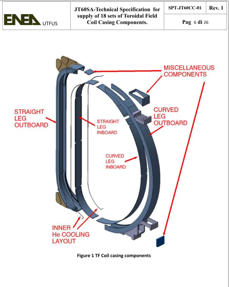
1.3 The TF coil casing
The TF coil casing mission is to embed and support the superconducting winding pack. Due to the embedding and assembling procedure, it has to be realized in 4 main parts intended to be welded at the end of the assembly procedure. Figure 1 depicts the lay-out of the casing divided into its parts.
2 Scope of Supply
The Contractor is asked to supply:
1. Two sets of mock-ups as described in §3.2.
2. Two groups of 9 complete sets each of TF Coil Casing Components.
3. The technical and quality documentation related to the manufactured items and the production process relevant aspects.
3 Deliverables
3.1 TF Coil Casing Components
The Contractor must provide 18 sets of TF Coil Casing Components, divided in two groups of 9 sets each. Each group will be delivered to a different TF coil manufacturer where the integration of the Winding Pack will be carried out. The two TF coil manufacturers are ASG Superconductors and Alstom.
Each TF Coil Case consists of 4 main parts: straight leg outboard, straight leg inboard, curved leg outboard and curved leg inboard. All the details needed for the manufacturing of all these parts are reported in the following referred drawings.
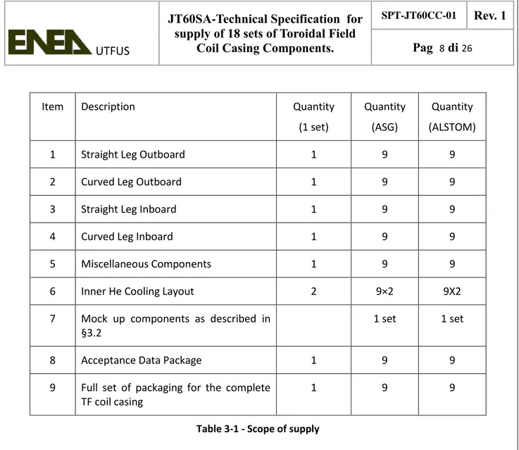
The items as shown in Table 3-1 are included in the scope of supply for a single set of Coil Casing Components.
Item Description Quantity (1 set) Quantity (ASG) Quantity (ALSTOM)
1 Straight Leg Outboard 1 9 9
2 Curved Leg Outboard 1 9 9
3 Straight Leg Inboard 1 9 9
4 Curved Leg Inboard 1 9 9
5 Miscellaneous Components 1 9 9
6 Inner He Cooling Layout 2 9×2 9X2
7 Mock up components as described in §3.2
1 set 1 set
8 Acceptance Data Package 1 9 9
9 Full set of packaging for the complete TF coil casing
1 9 9
Table 3-1 - Scope of supply
As far as the TF Coil is concerned (see Figure 1), two different welding are required:
1. A welding between the Straight leg and the Curved leg both on the inboard and the outboard side (Transverse welding). The thickness to be welded is about 50mm.
2. A welding between the outboard and the inboard part, both for Straight and Curved legs (Longitudinal welding) . The thickness to be welded is about 20mm.
These welding will be performed during the final assembly and are not part of this contract. Nevertheless, the TF Coil Casing Components have to be supplied with the proper preparation which shall be agreed between the Contractor and the two TF Coil manufacturers, basing on the welding procedure defined by the latter.
3.2 Mock-ups
The casing will be delivered by the Contractor to the Company in charge of inserting the winding pack into the coil casing, as a number of separate prefabricated components.
After insertion and wedging of the winding into the casing, the transverse and longitudinal welding of the closure plates will be performed by the winding pack manufacturers.
In order to define the welding process to be followed, it is needed to perform some tests and to qualify the welding procedure for both the transverse weld and the cover (longitudinal) weld. Demonstration of the quality of this weld will be achieved by the winding pack manufacturer through the use of mock-ups. In order for the winding pack manufacturer to carry out the welding tests, representative samples must be prepared by the casing contractor. The casing contractor shall
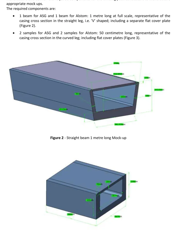
manufacture and deliver the required components for the winding pack contractors to manufacture appropriate mock ups.
The required components are:
1 beam for ASG and 1 beam for Alstom: 1 metre long at full scale, representative of the casing cross section in the straight leg, i.e. 'V' shaped; including a separate flat cover plate (Figure 2).
2 samples for ASG and 2 samples for Alstom: 50 centimetre long, representative of the casing cross section in the curved leg; including flat cover plates (Figure 3).
Figure 3 - Sample 50 cm long
3.3 Quality Documentation
The Contractor must provide complete documentation both for the manufacturing process and the deliveries. The documents have to be issued respecting the following schedule:
Prior to start the manufacturing of the mockups: 1. Quality Plan
2. Production Process description 3. Validation program.
4. Control Plan
During the manufacturing of the Mock-ups:
5. Chemical analysis, destructive and non destructive test reports for the raw material, the sub-assembly parts and welding of the Mockups.
Linked to the delivery of the mock-ups:
6. Validation Report for all the special process related to the mock-up construction 7. Acceptance data package for the mockups.
Prior to the manufacturing of the Casing Components 8. Validation Report for all the special process. During the manufacturing of the Casing Components:
9. Chemical analysis, destructive and non destructive test reports for the raw material and the parts used to assemble the Casing Components.
10. Reports of NDT during production welding. Linked to the delivery of the TF Coil Casing Components:
11. Acceptance data package for TF Coil Casing Components.
Apart of the reports, for all the test performed (both DT and NDT) the Contractor shall also store the relevant output of the test (digital signals time-histories, radiography etc.) on record.
The requirements for these documents will be explained in details throughout this document in the relative proper sections.
3.4 Reference documents
3.4.1 Codes and standards
During execution of the work the following codes and standards in their current revision shall be applied. In particular the following standards shall be applied:
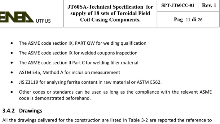
The ASME code section IX, PART QW for welding qualification
The ASME code section IX for welded coupons inspection
The ASME code section II Part C for welding filler material
ASTM E45, Method A for inclusion measurement
JIS Z3119 for analysing ferrite content in raw material or ASTM E562.
Other codes or standards can be used as long as the compliance with the relevant ASME code is demonstrated beforehand.3.4.2 Drawings
All the drawings delivered for the construction are listed In Table 3-2 are reported the reference to the single parts drawings.
Drawing number (ASG: CS1 to CS9) Drawing number (ALSTOM: CS10 to CS18) Rev Description 010301-503000 010301-503100 Casing Components
010301-503001 010301-503101 Straight Leg Outboard
010301-503003 010301-503103 Curved Leg Outboard
010301-503002 010301-503102 Straight Leg Inboard
010301-503004 010301-503104 Curved Leg Inboard
010301-503006 010301-503106 Inner He Cooling Layout
010301-503005 010301-503105 Miscellaneous Components 010301-503007 010301-503008 010301-503107 010301-503108 Mock-ups
Table 3-2 – TF Coil Casing Drawing Numbers.
Since the two TF coil manufacturers have different requirements for the amount of over material required in different locations of the casing two complete sets of drawings are provided, one for each coil manufacturer. The contractor shall take care to these differences in order to supply the proper casing components to each of the two TF coil manufacturing contractors.
3.5 Responsibilities
The Contractor: shall develop detailed design of the casing on the base of the preliminary design reported in Table 3-2;
shall prepare two complete sets of CATIA models and the associated CATIA drawings for the complete Casing Component Set, one for ALSTOM and one for ASG. These models are to be provided prior to manufacture. The models shall then be updated by the Contractor where a design deviation affects the geometry of the components throughout the whole manufacturing process;
shall inspect the incoming material and guarantee that it fulfill the requirements of this contract;
shall supply and provide all the Casing Components as required for the fulfillment of the contract;
shall use sub-contractors only with the authorization of ENEA. In this case the sub contractor shall be indicated in the Quality Plan and the responsibility of the performance and of the compliance of the parts involved in sub-contracting shall be of the Contractor;
shall be responsible to provide the supply with the proper packaging in order to deliver it perfectly;
shall ensure that all the Quality requirements are fulfilled and all the Quality Documentation are drawn, filled and signed.
ENEA shall provide the weld preparation drawings and the surface machining specification to the Contractor. Two different set of drawings, one for the ASG casings, the other for the Alstom casings; will be prepared based on the requirements of the two winding pack manufacturers.
4 Manufacturing
The coil casing components will finally provide the necessary containment and support to the 18 winding packs which will be embedded inside them.
Each single set consists of four main sub-components, as described in Table 3-2, which are represented together in exploded view of the final assembled casing in drawing number 010301-503000 for ASG and 010301-503100 for Alstom
The manufacture of the TF coil casing includes:
1.
Construction of the components2.
Machining of the internal surfaces3.
Weld grooves preparation4.
Installation of cooling channelThe mock-up manufacturing is based on a similar procedure following steps 1, 2 and 3.
4.1 Materials
Materials purchased by the manufacturer in plate form shall be made to ASTM 480 and ASTM A-240.
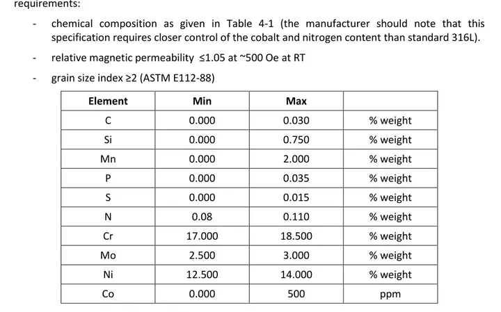
The coil casings shall be made from 316L austenitic stainless steel with the following specific requirements:
- chemical composition as given in Table 4-1 (the manufacturer should note that this specification requires closer control of the cobalt and nitrogen content than standard 316L). - relative magnetic permeability ≤1.05 at ~500 Oe at RT
- grain size index ≥2 (ASTM E112-88)
Element Min Max
C 0.000 0.030 % weight Si 0.000 0.750 % weight Mn 0.000 2.000 % weight P 0.000 0.035 % weight S 0.000 0.015 % weight N 0.08 0.110 % weight Cr 17.000 18.500 % weight Mo 2.500 3.000 % weight Ni 12.500 14.000 % weight Co 0.000 500 ppm
Table 4-1: Chemical composition of casing material
The mechanical requirements for the material at room temperature are specified in the corresponding ASTM code indicated above.
All materials must be certified as complying with the requirements of this section. In addition samples prepared according to both ASTM E1450-09 (tensile) and JIS Z 2284 (fracture toughness) from 10% of all plates and 10% of all forgings must be provided to ENEA for independent testing. The location of these samples will be provided by ENEA.
4.2 Identification
Each part (plate, sheet, strip) has to be marked by stamping or electric pencil in order to identify: 1. Supplier
2. Batch/Cast number 3. Lot/Forging number 4. Type/Grade of material
4.3 General Requirements
4.3.1 Workshop personnel
All personnel involved in any manufacturing operation shall be informed of the special requirements of the work associated with the TF Coil Casing Components manufacture. In particular:
It is essential that workshop personnel do not deviate in any way from the design, or make repairs to resolve any manufacturing issue, without ENEA involvement. As such, there must be an open channel of communication between workshop personnel and ENEA.
All personnel entering the area of the TF Coil Casing Components manufacture shall be formally informed of the importance of the points as noted in 4.3.2.
All welders must be qualified for the welding technique chosen. A copy of the welder’s license shall be provided.
Personnel performing NDT has to be qualified according to reference codes.
Personnel performing welding inspection has to be qualified according to reference codes. In relation to the above points, ENEA shall be present while workshop personnel are informed of these requirements.4.3.2 Cleanliness
All manufacturing operations shall be performed under clean conditions. Particular care must be taken to ensure the following:
Any other non related process which may be carried out in the vicinity of manufacture of the TF Coil Casing Components will not adversely affect the manufacture of the TF Coil Casing Components.
No painted or unpainted ferromagnetic material shall be allowed to be in contact with the TF Coil Casing Components. No ferromagnetic material dust or debris should be allowed in the manufacturing area of the TF Coil Casing Components.
All the tools used for the manufacturing of the TF Coil Casing Components, including clamps, hammers, brushes, welding tools, support, handlers, lifting and moving tools, must be suitable for Stainless austenitic steel.All the details about the cleanliness management shall be described in the Production Process Description.
4.3.3 Handling
During the manufacture of the TF Coil Casing Components, many handling operations are required. In order to minimise the risk of damage to any components due to handling operations being carried out, it is expected that the Contractor will pay close attention to all expected handling operations prior to commencement of the operation.
With reference to and meeting the requirements of 6.1, the Contractor shall submit a Detailed Procedure for all of the handling operations which are expected to be carried out during the
manufacturing process. In developing the Detailed Procedures, the Contractor will consider the complete manufacturing process, and will:
Attempt to carry out all manufacturing processes with a minimum number of intermediate handling operations;
Install suitable supports around the components to be handled to ensure that the components do not undergo plastic deformation;
Ensure that all pipes are protected from mechanical damage;
Ensure that the cooling channel ends are sealed and protected from the ingress of particulate or liquid material;
Not weld any equipment to any component of the TF Coil Casing Components e.g. lifting equipment;
Ensure that there is no direct contact between painted or unpainted ferritic steel and any of the TF Coil Casing Components;
Design and manufacture appropriate jigs and fixtures for all handling processes;The list of Detailed Procedures depends on the chosen manufacturing process(es), however, it is expected that a Detailed Procedure will be submitted for all the handling procedures including:
Lifting of all casing components;
Turning of all casing components;
Storage of all casing components;
Moving of the assembly during the preparation for the shipment.4.4 Construction
A number of raw materials will be procured by the Contractor and will be assembled into all casing components. The raw materials may be in form of plates, bars, tubes, ingots and the like. The Contractor remains responsible for choosing the construction technology, either forging, automatic welding, machining or similar, which best suits their manufacturing processes. However, for all processes, the Contractor shall submit a Detailed Procedure for endorsement by ENEA.
The construction of the casing components will include: Receipt of the raw materials (plates, ingots, tubes), Incoming inspection of all material certificates,
Acceptance tests on raw material, sampling the needed specimens, Forging of the ingots into formed parts, if required,
Bending/rolling of plates,
Acceptance tests on forged parts and/or plates, sampling the needed specimens, Welding of plates/formed parts into components,
Performing of NDT and
Cleaning and degreasing of the constructed components, sandblasting if required.
4.4.1 Technical Requirements
The Contractor shall organize a design review with the presence of ENEA in order to approve the detailed design.
The Contractor shall verify, after receipt of each batch of raw materials, that the material certificates are duly filled and complete, and that the requirements reported in 4.1 are met. The Contractor shall provide the facilities, either internal or by sub-contractors, needed for the
successful construction of the casing components: such facilities include, but are not limited to: o Welding stations and equipment (for the welding processes chosen by the Contractor) o Drop or press forging equipment (where forged parts must procured)
In case of sub-contracting, ENEA reserves the right to inspect the sub-contractor’s facilities during production of the casing components.
The Contractor shall combine the raw materials in the casing components using the process of their choice, being it either automatic/manual welding of smaller plates, or forging of large sections. Whatever the choice, it has to be described in the Quality plan and control plan by means of the needed Detailed Procedure and ENEA reserves the right to approve the process and to inspect the facility which carries it out.
The Contractor has to prepare detailed drawings of the assembly and of the parts to be welded including chamfers.
An overview of the Casing Components is given in drawing 010301-503000. The main structural parts of each casing set are the Straight Leg Outboard (drawing 010301-503001) and Curved Leg Outboard (drawing 010301-503003). These will be welded together by each of the two Coil Manufacturers to provide a supporting structure for the Winding Pack. The casing closure is completed by the welding of the Straight Leg Inboard (drawing 010301-503002) and Curved Leg Inboard (drawing 010301-503004).
4.4.2 Tooling Requirements
In order to satisfactorily construct the casing components, the following is required:
Suitable lifting equipment to handle the raw materials.
Suitable supports for storage and preparation of the raw materials.
Suitable jigs and fixtures to allow a controlled welding process and to limit distortions to a minimum.
Tooling needed to manufacture and transport the sub-assembly of the casings.4.4.3 Acceptance Testing/Other Measurements
If the casing components is obtained by welding parts, the non destructive test specified in the welding requirements have to be carried out. Details about welding are reported in 4.5.
The 100% of the parts obtained from forging ingot or bending/cutting plates have to be subjected to Acceptance test.
Firstly a visual examination have to be carried out to verify that cracks, scratch and, in general, surface defects are not present. Furthermore the parts are also required to pass ND exams. The Contractor will choose the more appropriate technique (radiographic test or ultrasonic test or other). The NDT procedure will need to be approved by ENEA and will be part of the Production Process Description.
The Acceptance Criteria have to be the defined applying the relevant International Standard depending by the process used (forging, bending, cutting etc.). The reference Standard, as well as the description of the control itself, shall be clearly indicated in the relevant Detailed Procedure. The opportunity of repairing a defect shall be considered case by case and shall ONLY be carried out AFTER agreement with ENEA. Repaired parts shall be submitted to the acceptance test once again. After final machining of the casing components, the following checks shall be carried out:
Geometrical survey of the inner surfaces of the casing inboard and outboard components. The survey could be carried out by using go-no go gauges, to check the channel widths, and/or 3D measuring devices (like touch probes, measuring arms, laser trackers, laser scanners and the like) to check for the flatness of the internal surfaces and the straightness of the internal channel profile.
4.5 Welding
"Weld quality shall be assured by the general provisions of the ASME Boiler and Pressure Vessel Code (“the ASME Code”). The following requirements apply to all welds:
1. All welding procedures must be qualified before welding commences according to the procedure given in Section IX, Article II, of the ASME Code. This means that a procedure is written for each weld to be performed, sample welds must then be performed with the as-supplied base material and filler material and subjected to tests to determine the chemical composition and mechanical properties of the joint. Both the procedure and the qualification of the procedure must be documented as described in the same article of the ASME Code. The coil cases will operate at 4K and all materials must comply with the toughness requirements of Section VIII Division 2 Part 3.11.4 of the ASME Code.
2. All welding personnel (welders and welding operators) must be qualified according to the procedure in Section IX of the ASME Code. This means that the people carrying out the work must have welded test coupons which have passed the inspections as described in Section IX, Article III.
3. Every weld must be subject to 100% visual inspection, following the procedure described in Section V, Article 9 of the ASME Code.
4. Every weld must be subject to 100% surface inspection for cracks using a dye penetrant technique, performed according to Section V, Article 6, T641 of the ASME Code. The fluids used shall be suitable for vacuum components.
5. Every weld must be subject to 100% volumetric inspection by radiography or, where this is not possible, by ultrasonic inspection. These techniques must be applied as described in Section V, Article 2 and Article 4 respectively of the ASME Code. In addition, where ultrasonic
inspection is used in lieu of radiographic examination, it must be carried out in accordance with ASME VIII Division 2 Section 7.5.5.
6. The acceptance criteria to be applied are those given in Section VIII, Division 2, Part 7.5 of the ASME Code, with the additional requirement that the largest permissible defect shall be smaller than 5 mm2 in area with an aspect ratio of 3:1.
In addition to the requirements of the ASME Code, for qualification purposes the following destructive tests shall be performed:
Tensile test at room temperature, 2 specimens; Impact test at room temperature, 2 specimens;
Tensile test at 4K, 2 specimens (2 specimens will be delivered to Fusion for Energy that will carry out the test under its responsibility);
Metallographic test: 1 macroexamination, 1 microexamination. For all welded parts the Contractor shall:
Prepare detailed drawings of the assembly and of the parts to be welded including chamfers; Define a pWPS, qualify the process (also drawing a WPQR) and finalize the WPS to be approved
by ENEA. The pWPS must include all the relevant parameters that can impact the characteristics of the welded joint, as prescribed by the reference rule.
4.6 Machining
The roughness of the internal surfaces is a key aspect in the winding pack embedding and impregnation. For this reason the casing components internal surface must be machined with care in order to achieve the specified levels of dimensional and geometrical tolerances as specified in the drawings.
External surfaces must be machined to remove excess material up to the values specified in the following sections.
Machining of the casing components internal surfaces includes:
Pre-machining of the channels inside the Straight Leg Outboard and Curved Leg Outboard components.
Stress relieving of the components, as required by the chosen manufacturing process. Final machining of the channel inside the Straight Leg Outboard and Curved Leg Outboard
components.
4.6.1 Technical Requirements
The geometry and the dimensional requirements of the internal casing surfaces are detailed in the Straight Leg Outboard drawing 010301-503001 and in the Curved Leg Outboard drawing 010301-503003.
It is suggested that the Contractor shall execute the machining of the components in two passes: the first coarse pass should be used to remove most of the material, from both the internal and (if necessary) external surfaces of the fabricated casing components, and it shall be followed by a stress relieving procedure in order to remove residual stresses due to welding and machining. After the stress relieving, the fine machining of the casing internal faces can be carried out. Modifications to this sequence of steps (coarse machining, stress relieving, fine machining) can be proposed by the Contractor, but ENEA reserves the right to review the procedure and accept the proposal.
The Contractor shall remove, after the fine machining phase, all traces of grease and dirt from the machined components, and provide a suitable space for their storage in the time lapse prior to the following manufacturing steps.
A Detailed Procedure is required describing the complete machining process. As a minimum, the following points shall be covered in the Detailed Procedure:
o Details of the chosen machine centre such as size, capacity and number of degrees of freedom of the cutting tool.
o The proposed orientation of the coil for each setup.
4.6.2 Tooling Requirements
In order to satisfactorily machine the casing components, the following is required:
A numerically controlled milling machine, able to machine each casing segment with an accuracy of at least 0.1 mm, possibly with the component fixed in a single position, shall be used for the machining of the casing components. Alternative solutions may be proposed, but ENEA reserves the right to review the procedure and accept the proposal.
4.6.3 Acceptance Testing/Other Measurements
After machining of the casing components, for those surfaces which were exposed by the machining passes, the following checks shall be carried out:
Visual inspection to verify that the external surface is free of defects.
The Contractor may execute the inspection of the non-machined surfaces, as reported in 4.4.3, at this same point in time. This choice has to be documented in the official test results. A geometrical survey of the machined surfaces to confirm compliance with the values specified in drawing number 010301-503001 (Straight Leg Outboard) and in drawing number 010301-503003 (Curved Leg Outboard).
A three dimensional mapping of the inner surface to be carried out with the proper method (laser tracking or equivalent). This will be supplied to the TF coil manufacturer in order to compare the map with the winding pack one and support the embedding operation.
4.7 Weld grooves preparation
The machined casing components must be prepared for the welding operations which will be carried out during integration of the Winding Pack in the casing. These operations, that will be carried out by the TF Coil manufacturer contractor, include:
Execution of transverse welds, which are relatively thick (~ 50 mm) butt welds applied on the three thick sides of the casing cross section, between the inboard and outboard casing components.
Execution of longitudinal welds, which are relatively thin (~ 20 mm) fillet or butt welds applied between the casing components and their closure plates.
The Contractor shall take care of the preparation of the parts to be welded as agreed with the TF Coil manufacturers. Before the manufacturing of the first complete set of casing components ENEA will supply the relevant drawings basing on the TF coil manufacturers needs. Being two different contractors in charge for the final assembly of the magnet it is expected that two different sets of drawings will be supplied clearly marked with the relevant winding pack manufacturer's name. Weld grooves preparation will include:
Machining of the inboard and outboard casing components Machining of the inboard and outboard closure plates
4.7.1 Technical Requirements
The precise details of the weld grooves shall be agreed with the TF Coil Manufacturer Contractors under the ENEA supervision, prior commencing of the execution, on the basis of the requirements coming from the coil manufacturer. Since there are two different coil manufacturers, each taking care of nine coils, it is possible that two different sets of weld preparations will be requested, on the basis of the individual preference of the manufacturers. It is expected that the TF coil manufacturers will work with the Contractor to define the weld preparation detail to suit their manufacturing process.
The TF coil casing welding design will be agreed with the TF Coil Manufacturer under ENEA coordination. Consequently the preparation of the grooves, including the chamfer shape and dimension, the surface condition and extra material must be compliant with the foreseen weld execution method.
The location of the weld grooves is indicated in drawing number 010301-503001 (Straight Leg Outboard) and in drawing number 010301-503003 (Curved Leg Outboard).
4.7.2 Tooling Requirements
In order to satisfactorily prepare the weld grooves, the same machining requirements reported in 4.6.2 must be met.
4.7.3 Acceptance Testing/Other Measurements
After machining of internal surfaces the Contractor shall perform geometrical checks of all weld grooves, either by using rigid templates or 3D measuring devices thus ensuring that the geometry, the dimension and the surface roughness meet the TF Coil assembly Contractor requirements.
4.8 Installation of the cooling channel
The Straight Leg Outboard casing component is equipped with two internal cooling channels, one per side, which are first fitted in curved grooves machined in the component curved sections and then welded all along the straight part of the component itself. Each channel has two termination pipes, of round section, which penetrate the component side wall through slightly oversized holes. Installation of casing cooling channel includes:
Manufacture of the cooling channel by bending and welding.
Preparation of channel grooves and holes in the Straight Leg Outboard component. Welding of the cooling channel along the Straight Leg Outboard component.
4.8.1 Technical requirements
The Contractor must form the tube according to the requirements reported in drawing 010301-503006 for ASG and drawing number 010301-503106 for Alstom. Bending must be carried out using equipment equipped with non-ferromagnetic rollers, to avoid contamination of the stainless steel of the tubes.
Provisions must be taken in order to avoid squeezing or buckling of the pipe during bending. After bending the pipe must be thoroughly cleaned from any traces of inert material.
The tube must be closed at both ends, by using welded plugs. Openings must be drilled on the side wall and the round termination pipe must be welded in place.
The extension of the termination pipe must be sufficient to allow welding of the external cooling line after the final impregnation of the casing.
The Straight Leg Outboard component must be machined in order to create the groove for the insertion of the cooling channel, and passing holes must be prepared where the termination pipes crosses the segment lateral plates.
The cooling channel must be welded on the straight section of the Straight Leg Outboard component channel walls, up to the insertion in the grooves of the top/bottom curved parts of the Straight Leg Outboard component. The welds must ensure that no trapped volume is created between the casing and the pipe. The weld must be a continuous weld along the entire length of the tube.
It must be demonstrated that there is no major blockage of the cooling channel. This could be done by endoscopic examination or pressure drop measurement. The Contractor shall agree the procedure with ENEA prior to the commencement of manufacturing.
4.8.2 Tooling Requirements
In order to satisfactorily install the cooling channels, the following is required:
The bending tools must be equipped with non-ferromagnetic rollers, and no ferromagnetic part of any kind shall be in contact with the cooling tube at any time during the forming process.
Appropriate supports and fixtures to be used during forming and storage. Appropriate clamping tools to be used during welding process.
Appropriate welding tools.
Non destructive weld testing equipment. Pressure testing equipment.
4.8.3 Welding
For the welding of the cooling channel the Contractor has to:
Prepare detailed drawings of the assembly and of the parts to be welded including chamfers (if any);
Define a pWPS, qualify the process (also drawing a WPQR) and finalize the WPS to be approved by ENEA
4.8.4 Acceptance Testing/Other Measurements
After welding of the cooling tube in the Straight Leg Outboard component, the following checks shall be carried out, under an independent THIRD PARTY INSPECTION AUTHORITY, to certify that activities are carried out in accordance with the agreed codes and standards:
Leak test of the cooling channel. The leak rate at 2.5 MPa must be less than 10-8Pa·m3 / s. Pressure test of each cooling channel using nitrogen or helium at 2.5 MPa, for one hour
time.
The Supplier shall arrange free access for the inspector(s) to his works or at the works of his subcontractor’s, so that the inspector(s) may carry out his duties as described. The Supplier shall provide the inspector(s) with copies of all relevant test reports and other facilities, as may be necessary, so that he is able to certify that deliverables meet the technical requirements.
5 Delivery Requirements
The casing components will be delivered as welded components prepared for winding pack insertion. The surfaces will be machined according to the geometry, the dimensions, the roughness and the tolerances defined in the drawings.
To confirm that the fabrications are within specification, a series of acceptance tests are made during manufacture (see 6.5). A report detailing the results of the acceptance tests will be made available to the Contractor. The acceptance tests include:o Non destructive testing of all welds;
o Conformity check on all material certificates;
o For the ASG casing components, detailed measurement of key dimensions as shown in drawing numbers 503001, 503002, 503003, 010301-503004, 010301-503005 and 010301-503006.
o For Alstom, detailed measurement of key dimensions as shown in drawing numbers 010301-503101, 010301-503102, 010301-503103, 010301-503104, 010301-503105 and 010301-503106 for ASG.
The components will be free from burrs and sharp edges.
The components will be cleaned and free from oil or other debris.
The components will be uniquely labelled
The packaging is designed to ensure there are no permanent deformations in the structures during road transport. The packaging is designed to allow the components to be stored outside.5.1 Packaging
The Contractor is responsible for the design and manufacture of the packaging for the casing components. As such, the Contractor shall submit a Detailed Procedure in accordance with the requirements of the Validation program, describing the complete proposed packaging arrangement. The Detailed Procedure shall consider the following key points:
Each set of casing components must be packaged in a suitable fashion for road transport up to its specific coil manufacturing site (ASG SUPERCONDUCTORS Genova, Italia; ALSTOM Belfort, France) .
Each set of casing components must be protected from moisture by usage of absorber bags and application of air-tight plastic wrap.
The casing components shall be fitted with suitably located accelerometers to confirm that they have not undergone accelerations greater than 5 g during transport.
The cooling channels must be sealed.5.2 Destination
There are two manufacturers of the TF coil integration whose sites are in Italy and in France. In any case, the Contractor is the sole responsible for the delivery of each set of casing components to each of the two different coil manufacturing facilities.
The Contractor is asked to supply a complete documentation related to all the aspect of the production process as well as a proper set of documents accompanying each set of Mock-ups and Casing Components delivered.
6.1 Quality plan and control plan
The Contractor shall supply a quality plan and a control plan basing on the requirements specified in the Management Specification.
6.2 Production Process description
The Contractor shall propose a complete Production Process description covering all the steps, from the acceptance of the raw material to the delivery of the TF Coil Casing Components. The Production Process description shall list all the various production phases and issue dedicated Detailed Procedures for those steps which are deemed by Contractor as “special processes”. The whole Production Process description, including the Detailed Procedures, shall be submitted to ENEA for approval prior to the commencement of the manufacturing process. Since ENEA relies on the experience of the Contractor to define the production process, the responsibility of product quality compliant with the Technical specification requests after following the procedure remains with the Contractor.
Basing on the approved Production Process Description, ENEA will define the preliminary Control Point list.
6.3 Validation program
It is expected that some parts of the manufacturing activities will include special processes (those for which a Detailed Procedure is required, see 6.1) that need to be validated prior to the production stage. The Validation Program shall include the list and the detailed description of such processes. Validation could be carried out using any of the following means:
• Manufacture and testing of one or more partial mock-up which is representative of the final design geometry using the proposed manufacturing processes, or
• By review of similar manufacturing processes which have been carried out previously in the same facility, and have demonstrated success in a similar operating environment.
In any case, the Contractor shall provide suitable documentation to demonstrate confidence in the process.
The manufacturing of the mockups described in 3.2 could be part of the validation program as far as the building of the mock-up is based on the same processes that will be used to manufacture the Casing Components.
Being the welding a special process, it shall be surely included in the validation program. A preliminary Welding Procedure Specification shall be prepared by the Contractor for each welding to be performed in the manufacturing process. Each WPS shall include the details about the welding process, the geometry of the part to be joined and the preparation (by means of detailed drawings) and the relevant welding variables (arc current and voltage, consumables, backing/shielding, welding
position, number of run, position etc.). A WPQR shall be prepared at the end of the welding validation phase and be referenced by the WPS.
6.4 Validation Report for all the special process
The Validation of special processes should be documented issuing a Validation Report for each item foreseen in the Validation Program. Such Report shall include the description of the activities performed to demonstrate the effectiveness and the repeatability of the process, together with the results of the test carried out to confirm the fulfillment of the requirements. Hence, visual inspection, geometrical check, destructive test on mock-up, non destructive test, etc. should be part of the Validation report.
Validation shall be performed for all the welding process issuing the needed Welding Procedure Specification. The WPS must include all the information relevant to identify the welding process, to control the repeatability and to supply the instruction to the welding operators. The WPS shall be available for reference by welders or welding operators, the responsible welding engineer and the authorized Inspector.
The information included in the WPS must be compliant with the requirements of the reference standards. A Welding Procedure Qualification Report must support the WPS and shall contain the details about the method of qualification (mockup or similar process already qualified or standard welding procedure reference). The number and the type of Destructive and Non Destructive test must be at least compliant with the reference standard and furthermore integrated with the test required for the specific component as described in the relative paragraph in this document. WPS and WPQR together with the reports for the DT and NDT performed during qualification for all the welding foreseen shall be included by the Contractor in the Validation Report.
6.5 Acceptance Data Package
For each set of TF Coil Casing Components, an Acceptance Data Package shall be compiled. The requirements will be defined in detail by ENEA that will issue a report format after the approval of the quality documents. Basically the Acceptance Data Package will include at least:
All certificates of successful passing of all the required quality checks or tests in all the production stages: raw material, unfinished parte stage, delivery and final test. These documents must include report from :o NDT;
o Helium channel leak check;
o chemical and material performance test (both for raw materials and for forged ingots and/or bent plates);
o 3D measurements (e.g. laser tracking)
Identification number for all the billet used to realize parts and or sub-assembly.
Travellers with the evidence by signature of the executing person for each production phase.
Details of any modifications made to the Detailed Procedure including a description of why the modifications were required (i.e. approved Deviation Request).
Records detailing any design changes which have been agreed and incorporated in the actual manufacturing process (i.e. approved Deviation Request). Where design changes have been carried out, the following shall be included:o the technical details of the design change,
o the implications of the design change on the manufacturing process, and o agreement reached with ENEA for the design change.
Non conformity reports (if any) including the following details: o detail of the non conformity,o proposed resolution for the non conformity including supporting analysis,
o agreement reached with ENEA and, where appropriate, F4E, for the resolution of the non conformity,
o formal communication that the non conformity case has been solved.
Drawings of the Component “as built” in case of non conformity that impact the dimensions, the geometry or the tolerances. Otherwise is intended that the components delivered perfectly fit the drawings.
Results of all measurements carried out during manufacture.
Material certificates for all raw materials, including welding materials, used during the manufacturing process.All of the above documentation shall be included in the Acceptance Data Package for each set of TF Coil Casing Components set and must be delivered together with the components themselves. The documentation shall be complete and self consistent, containing also the records already supplied during the manufacturing phase.
TITLE
JT60SA-Management Specification for supply of
18 sets of Toroidal Field Coil Casing Components.
CLASSIFICATION: C
Association EURATOM-ENEA
Agenzia nazionale per le nuove tecnologie, l’energia e lo sviluppo economico sostenibile
This document specifies the quality and management requirements:
the Bidder shall comply when preparing its offer/proposal;
the Supplier shall comply within the course of the Contract.
The description of the Supplier quality management system shall be established in a dedicated
QUALITY PLAN for managing ENEA work activities.
This document is issued for the execution of the Agreement of Collaboration between Fusion for Energy,
CEA and ENEA for the joint implementation of the procurement arrangement for the design and
manufacture of the toroidal field magnet for the Satellite Tokamak Programme.
Rev. 0 of 10 October 2011
0
10/10/2011
Paolo Rossi
Luigi Di Pace
Antonio Cucchiaro
Table of Contents
1. PURPOSE ... 4 2. DELIVERY TIME SCHEDULE ... 5 3. Ownership and responsibilities ... 6 4. SCOPE OF THE SUPPLIER QUALITY PLAN ... 6
4.1. AT TENDER (OR PROPOSAL) LEVEL ... 7 4.2. AT CONTRACT LEVEL ... 7
5. RESPONSIBILITIES ... 8
5.1. ENEA RESPONSIBILITIES... 8 5.2. SUPPLIER RESPONIBILITIES ... 8
6. QUALITY PLAN REQUIREMENTS ... 9
6.1. OBJECTIVES AND DELIVERABLES OF THE CONTRACT ... 9 6.2. RESPONSIBILITIES REQUIREMENTS ... 9 6.3. CONTRACT MANAGEMENT ... 10 6.4. WORK BREAKDOWN STRUCTURE (WBS)... 11 6.5. CONTROL PLAN ... 11 6.6. TIME SCHEDULE MANAGEMENT ... 12 6.7. RESOURCE MANAGEMENT ... 15 6.7.1. Special Processes Qualification ... 15 6.7.2. Staff Qualification ... 15 6.7.3. Material resources ... 16 6.8. NON CONFORMITIES AND DEVIATIONS MANAGEMENT ... 16 6.8.1. Management of Deviations ... 16 6.8.2. Nonconformity Management ... 17 6.8.3. RECORDS Management ... 18 6.9. INFORMATION AND DOCUMENTATION MANAGEMENT ... 18 6.9.1. Drawing Control ... 19 6.10. SUBCONTRACTING MANAGEMENT ... 20 6.11. ASSESSMENT AND VALIDATION MANAGEMENT ... 20 6.11.1. Measuring and Test Equipment ... 21
6.12.1. Supplier Review of the acceptance data packages and supplier release note ... 21 6.12.2. DELIVERY OF A COIL casing set ... 22 6.12.3. Acceptance OF A COIL casing set ... 22 6.13. CONTRACT RISK MANAGEMENT ... 22 6.14. HEALTH & SAFETY ... 22 6.15. CODES (REGULATORY DOCUMENTS) AND STANDARDS ... 22
7. QUALITY PLAN UP-DATE AND VALIDATION ... 23 8. INSPECTION AND Quality AUDIT VISITS ... 23
8.1. AUDITS AND SURVEILLANCE ... 23 8.2. ENEA OBSERVERS ACCESS ... 24 8.3. THIRD PARTY INSPECTION AUTHORITY ... 24
9. MANDATORY DOCUMENT FORMATS ... 24
9.1. ELECTRONIC DOCUMENTS ... 25 9.2. CONTROL PLAN FORM (WORK SCHEDULE) ... 27 9.3. DEVIATION REQUEST ... 28 9.4. NONCONFORMITY REPORT ... 29 9.5. DOCUMENTATION SCHEDULE FORM... 30 9.6. SUBCONTRACTING SCHEDULE FORM ... 31 9.7. SUPPLIER RELEASE NOTE ... 32
TERMS AND DEFINITIONS
Term Definition Acronym
Acceptance Data
Package Is the documentation package linked with a deliverable to be submitted by the supplier ADP Fusion for Energy The European Joint Undertaking for ITER and the Development of Fusion Energy F4E ENEA Technical
Responsible Officer
ENEA’s responsible for communicating all technical contractual actions and decisions to the Supplier
TRO
IPR Intellectual Property Rights IPR
Supplier Technical Responsible Officer
Supplier’s responsible for communicating all technical contractual actions and decisions to ENEA
KOM Kick-Off Meeting of the Contract KOM
Subcontractor All economic operators who supply items to the Supplier under the Contract
WBS Work Breakdown Structure WBS
Supplier
The supplier is the Contractor as defined in the supply Contract.
The successful Bidder (Tenderer or Applicant) is referred in the document as the “supplier”. The supply-chain follows the scheme below
Supplier -> Customer (ENEA)
Bidder The Bidder is the tenderer for the supply or service Contract (economic operator tendering for).
REFERENCE DOCUMENTS
[1] JT-60SA Integrated Project Team Common Quality Management System (CQMS) [2] EU-Quality Management System (EU-QMS)
1. PURPOSE
This document specifies the quality and management requirements that:
the Bidder shall comply with when preparing its offer/proposal;
the Supplier shall comply with during the course of the Contract.
The subject of this contract is the manufacture of the 18 sets of TF coil casing components, 2 sets of mock-up
components, works acceptance tests, packaging . The contract also includes the delivery of nine sets of TF coil casing
components to ASG SUPERCONDUCTORS (Genova, Italia) and the other nine to ALSTOM (Belfort France) for the subsequent coil integration activities with the winding pack and for the final coil machining.
The associated technical specification defines the detailed technical requirements for the coil casing components manufacture, transport frame, packaging and associated documentation (acceptance data package). Additionally, technical information associated with delivery requirements for the components are provided.
The quality management system of the Supplier and their Subcontractors implemented to complete the work shall be compliant with the requirements defined in this document and in the technical specification.
The description of the Supplier quality management system shall be established in a dedicated Quality Plan for managing ENEA work activities. This Quality Plan shall:
comply with the requirements defined in §6, and
2. DELIVERY TIME SCHEDULE
Considering that the contract signature date will be within week 20/2012, the mock-ups components and the eighteen packaged coil casing components sets with their associated transport frame and acceptance data package shall be delivered to ASG SUPERCONDUCTORS (9 sets) and ALSTOM (9 sets) according to the following time schedule:
Mock-up components 50/2012
Coil Casing Set (CS) 1 delivery week/year 35/2013
Coil CS 10 delivery 41/2013 Coil CS 11 delivery 47/2013 Coil CS 2 delivery 01/2014 Coil CS 12 delivery 07/2014 Coil CS 3 delivery 13/2014 Coil CS 13 delivery 19/2014 Coil CS 4 delivery 25/2014 Coil CS 14 delivery 31/2014 Coil CS 15 delivery 37/2014 Coil CS 5 delivery 43/2014 Coil CS 16 delivery 49/2014 Coil CS 6 delivery 03/2015 Coil CS 17 delivery 09/2015 Coil CS 18 delivery 16/2015 Coil CS 7 delivery 22/2015 Coil CS 8 delivery 38/2015 Coil CS 9 delivery 53/2015
3. OWNERSHIP AND RESPONSIBILITIES
After acceptance by ENEA of the provisional acceptance data package (ADP, quality documentation to be provided with each delivered coil for the works acceptance), the Supplier will be responsible for the transport of the coils to ALSTOM in France and ASG Superconductors in Italy. The acceptance data package will only be complete after completion of the transportation.
Upon delivery ENEA or its representative will sign a ‘receipt note’ (recognition of receipt only) if the deliverable is in the specified conditions, and the transport was performed as required.
The responsibility for the coil is then transferred to the organization in charge of the subsequent coil integration activities with the winding pack and for the final coil machining ( ALSTOM and ASG SUPERCONDUCTORS).
ENEA will declare the deliverable conformity by issuing an ‘Acceptance Note’ if the coil casing components comply with the technical specification and contractual requirements. The ownership of the coil is then transferred from the
Supplier to ENEA, and contextually from ENEA to ALSTOM or ASG SUPERCONDUCTORS.
ENEA signature of the Acceptance Note shall not relieve the Supplier from any contractual obligations and responsibilities.
4. SCOPE OF THE SUPPLIER QUALITY PLAN
The Quality Plan to be provided by the supplier shall describe the operational quality system implemented by the Supplier to ensure that:
Contract requirements will be met, and
Evidence of such compliance will be maintained.
The Quality Plan may be a single document that covers the whole scope of the Contract, including work performed by Subcontractors or it may be an assembly of separate well identified documents.
The structure of the Quality Plan should follow the structure of the section 6.
The Quality Plan shall encompass all activities performed in connection with the Contract. The level of detail in the Quality Plan shall be consistent with:
The technical requirements of the Contract;
The complexity of the economic operators, functions and activities involved;
The degree of design innovation;
The involvement of innovative processes;
Design, performance or manufacturing margins.
The compliance of the Quality Plan with this document shall replace any need for QA certification. Nevertheless in presence of QA certification of the Supplier, the related documentation shall be provided.
4.1. AT TENDER (OR PROPOSAL) LEVEL
The Bidder shall provide, in its offer/proposal a meaningful outline of a preliminary dedicated Quality Plan where the plans, schedules and explanation of the provisions to comply with the following requirements will be assembled.
During offer/proposal, due to the nature of the process, the Bidder might not have all the information that they will have as a successful Bidder. As result of this limitation, at this stage the Quality Plan cannot be a “complete” version and is referenced as an “outline’ version where:
Some sections will be addressed as a description of the proposed system.
The remaining sections shall have the description of the Bidder’s current system.
4.2. AT CONTRACT LEVEL
After the Contract signature, the Quality Plan shall encompass the following sequential stages:
1. at the kick-off meeting the parties shall agree on the improvement of the preliminary Quality Plan and on
the particular provisions to include in it;
2. 60 days after the kick-of-meeting the supplier shall issue the updated quality plan to ENEA for approval.
3. the Supplier shall not begin any manufacturing or purchase activity without the Quality Plan being
approved in writing by ENEA;
4. during Contract implementation, the Supplier shall update the Quality Plan (or parts of it) as/if required and shall submit it for approval to ENEA.