_______________________________________________________________________________________________
ACKNOWLEDGEMENT
The financial support of The Education, Audiovisual and Culture Executive Agency –
EACEA/European Commission within the “Erasmus Mundus Doctorate in Membrane
Engineering – EUDIME” (ERASMUS MUNDUS Programme 2009-2013, FPA n. 2011-0014,
SGA n. 2014-0970) is kindly acknowledged.
i
Contents
Summary ... 1 Sommario ... 4 Samenvatting ... 7 CHAPTER 1: ... 9 INTRODUCTION ... 91. Energy and targets ... 10
2. Salinity gradient energy ... 11
3. Theory ... 13
4. Reverse Electrodialysis ... 15
5. Challenges related to RED components ... 18
5.1. Ion exchange membranes ... 18
5.2. Spacers ... 28
5.3. Electrode and electrolyte solution ... 30
6. Conclusion ... 31
7. References ... 32
CHAPTER 2: ... 37
REVERSE ELECTRODIALYSIS PERFORMANCE FOR RIVER WATER/SEAWATER MIXING ... 37
1. Introduction ... 38
2. Materials and Methods ... 42
2.1. Solutions ... 42
2.2. Reverse Electrodialysis Setup... 43
2.3. Ion Chromatography ... 44
2.4. Electrochemical Impedance Spectroscopy ... 44
3. Results and discussion ... 46
3.1. SGP-RE tests ... 46
3.2. Uphill transport ... 51
3.3. Electrochemical Impedance Spectroscopy ... 53
4. Conclusion ... 56
5. References ... 57
CHAPTER 3: ... 61
ii
1. Introduction ... 62
2. Materials and methods ... 65
2.1. Solutions ... 65
2.2. Salinity gradient power-reverse electrodialysis setup ... 65
2.3. Electrochemical impedance spectroscopy setup ... 68
2.4. Ion transport analysis ... 69
2.5. Statistic ... 70
3. Results and discussion ... 71
3.1. Salinity Gradient Power-Reverse Electrodialysis performance ... 71
3.2. Electrochemical Impedance Spectroscopy test results ... 74
3.3. Ion transport ... 77
4. Conclusion ... 80
5. Acknowledgments ... 82
6. References ... 82
CHAPTER 4: ... 85
ASYMMETRIC CATION EXCHANGE MEMBRANE PREPARATION BY SULFONATED POLYSULFONE FOR REVERSE ELECTRODIALYSIS ... 85 1. Introduction ... 86 2. Experimental ... 89 2.1. Materials ... 89 2.2. Sulfonation ... 89 2.3. Polymer Characterization... 90
2.3.1. Fourier Transform Infrared (FTIR) ... 90
2.3.2. Nuclear Magnetic Resonance (NMR) ... 90
2.3.3. Membrane preparation ... 90
2.4. Membrane characterization ... 91
2.4.1. Permselectivity ... 91
2.4.2. Resistance ... 92
2.4.3. Morphology ... 94
3. Results and discussion ... 95
3.1. FTIR ... 95
3.2. 1H NMR ... 96
iii
3.4. Co-solvent addition ... 100
3.4.1. Characterization of membranes which DMF used as main-solvent ... 101
3.4.2. Characterization of membranes which NMP used as main-solvent ... 103
3.5. RED performance of selected membrane ... 104
3.5.1. Permselectivity ... 105
3.5.2. Non-gradient resistance ... 106
3.5.3. Gradient resistance ... 108
3.6. Theoretical power density calculation ... 109
4. Conclusion and outlook ... 110
5. References ... 112
CHAPTER 5: ... 115
IMMERSION PRECIPITATION CATION EXCHANGE MEMBRANE PREPARATION BY SULFONATED POLYETHERSULFONE FOR REVERSE ELECTRODIALYSIS... 115
1. Introduction ... 116 2. Experimental ... 119 2.1. Materials ... 119 2.2. Membrane Preparation ... 120 2.3. Membrane Characterization ... 121 2.3.1. Permselectivity ... 121 2.3.2. Resistance ... 122 2.3.3. Morphology ... 124
3. Results and Discussion ... 125
3.1. Membranes by solvent evaporation ... 125
3.2. Membranes by immersion precipitation ... 126
3.3. RED performance of selected membranes ... 132
3.3.1. Permselectivity ... 132
3.3.2. Non-gradient resistance ... 133
3.3.3. Gradient resistance ... 134
3.3.4. Theoretical power density calculation ... 135
4. Conclusion and outlook ... 137
5. References ... 138
CHAPTER 6: ... 140
iv
1. General Conclusion ... 141
2. Outlook ... 144
2.1. Strategies for complex solutions ... 144
2.2. Membrane production by wet phase inversion ... 145
2.3. Integrated membrane application ... 146
3. References ... 147
1
Summary
Reverse Electrodialysis for Energy Recovery: Material Development and Performance Evaluation
Salinity Gradient Power- Reverse Electrodialysis (SGP-RED), so-called blue energy, is a promising untapped membrane based renewable and sustainable energy generation technology. Salinity gradient energy can be defined as the energy reveals during the mixing of two solution having different concentration. Creating a controlled mixing in a RED stack gives the opportunity to transfer the mixing energy directly to electricity by redox reactions. Alternate arrangement of cation exchange membranes (CEM) and anion exchange membranes (AEM) form the required compartment design for controlled mixing. When high and low concentration solutions are fed from neighboring compartments, electrochemical potential difference of the solutions drive the ions from high to low concentrations. However, only charges opposite to membrane fixed charge can diffuse through, i.e. for an ideal membrane only cations can transport through CEM. Therefore, an ionic flux can be generated inside of the stack.
Understanding the fundamentals of the technology and the present challenges of SGP-RED is very important for the evaluation of the experimental study. Therefore, Chapter 1 deals with the theory behind SGP-RED, potential of current state of art and challenges on performance and commercialization.
Most of the RED literature investigate RED performance by using artificial solutions that only contains NaCl. In Chapter 2, the effect of real river and seawater solutions (collected from river of Amantea, Italy) is experimentally investigated on lab-scale RED stack prototype. Different flow rates and temperature are studied to find an optimized condition. RED effluents are characterized to have a better understanding on transport mechanisms of monovalent and multivalent ions. Ion characterization results indicate multivalent ions tends to transport against their concentration gradient. Moreover, investigations on electrochemical properties concludes Mg2+ has the most
severe effect on RED performance by causing an order of magnitude reduction on CEM conductivity.
2
After concluding drastic negative effect of Mg2+ on power generation in the second chapter,
Chapter 3 is dedicated to investigate broad range of magnesium content in mixing brine and
seawater. Magnesium is known as second most abundant cation in the natural seawater solution and concentration varies from region to region. 0.5 and 4 molal solutions from 0 to 100 % Mg2+ content are tested in RED setup. Ionic characterization of outlet solution is completed to see effect of concentration on transport of ions. It is observed that uphill transport is limited to 0 – 30% of MgCl2. Ohmic and non-ohmic resistance of the CEM and AEM characterized in the test solutions.
Resistance characterization reveals that cation exchange membrane resistance is critically affected by Mg2+ concentration while resistance of AEM remains unaffected.
Due to RED is a non-commercialized technology, there is no commercial ion exchange membranes designed for RED. Therefore, most of the RED studies investigates electrodialysis (ED) membranes because of the similarity. In Chapter 4, cation exchange membranes are prepared considering the needs of RED. A well-known polymer, polysulfone, is sulfonated by chlorosulfonic acid to obtain negatively charged polymer. After the characterization of the polymer, CEMs are prepared with an asymmetric porous morphology by wet phase inversion method. Phase inversion parameters, e.g. solvent type, co-solvent ratio, are studied to optimize the membrane resistance and permselectivity. Among the prepared membranes, most promising one is further characterized for different NaCl concentration to estimate the power density. The results encourage to consider wet phase inversion method as a fabrication method for CEM.
Commercial cation exchange membranes are produced as dense homogeneous membranes by functionalized polymeric materials as standalone or into a support to have a mechanical stability. In Chapter 5, sulfonated polyethersulfone membranes are prepared by wet phase inversion and solvent evaporation method. In solvent evaporation method, polyethersulfone/sulfonated polyethersulfone blend ratio is optimized considering electrochemical and mechanical properties. In wet phase inversion, effect of co-solvent, evaporation time, coagulation bath composition and concentration are studied to optimize the membrane electrochemical properties. Best performing wet phase inversion membrane, solvent evaporation membrane with corresponding ion exchange capacity and a benchmark commercial membrane CMX (Neosepta, Japan) are characterized to estimate RED performance for different solution concentration. Competitive results point out the possibility of CEM production by wet phase inversion.
3
Chapter 6 is dedicated to conclude and discuss the achievements of the conducted work. In
addition, some outlook for the future works was mentioned based on the deductions of the experimental work
4
Sommario
Elettrodialisi Inversa per il Recupero di Energia: nuovi materiali e prestazioni.
L’Elettrodialisi Inversa per la produzione di energia da Gradienti Salini (SGP-RED), o “Blue
Energy”, é una promettente e innovativa tecnologia a membrana che consente la generazione di
energia rinnovabile ed eco-sostenibile. L’energia da gradienti salini é legata alla miscelazione di due soluzioni aventi diversa concentrazione: quando tale processo è condotto in modo controllato in un’unità RED, l’energia libera di miscelamento è convertita in elettricità tramite lo svolgimento di reazioni redox agli elettrodi. In particolare, l’alternanza di membrane a scambio cationico (CEM) e anionico (AEM) costituisce la soluzione tecnologica attraverso la quale si promuove un flusso controllato di cariche. Quando soluzioni ad alta e bassa concentrazione sono alimentate in due compartimenti adiacenti, la differenza di potenziale elettrochimico indirizza il flusso di ioni dal compartimento più concentrato (HCC) a quello più diluito (LCC). Tuttavia, la presenza di membrane permselettive consente la diffusione solo degli ioni aventi carica opposta (contro-ioni) rispetto alle cariche fisse della membrana: idealmente, le AEM (con cariche fisse positive) consentono esclusivamente il trasporto di anioni e, viceversa, le CEM (con cariche fisse negative) consentono esclusivamente il trasporto di anioni. In ultima analisi, la segregazione delle cariche genera, ai capi degli elettrodi, una differenza di potenziale.
La comprensione dei principi e dei limiti della tecnologia RED costituisce la premessa per l’impostazione dello studio sperimentale. Il Capitolo 1 del presente lavoro di tesi analizza gli aspetti teorici alla base del processo RED, lo stato dell’arte e le sfide da affrontare per migliorare le attuali prestazioni della tecnologia e renderla commercializzabile.
In molti degli studi presenti in letteratura, le prestazioni della RED sono valutate rispetto a soluzioni artificiali di NaCl. Nel Capitolo 2, invece, si analizza sperimentalmente – su un prototipo RED in scala laboratorio – l’effetto di miscelazione di acqua di fiume e di acqua marina naturali (campionati da siti in Amantea, Italia) al fine di ottimizzare le condizioni operative rispetto a portata di alimentazione e temperatura. La caratterizzazione ionica delle correnti in uscita al modulo RED consente una migliore comprensione dei meccanismi di trasporto degli ioni monovalenti e multivalenti: i risultati indicano che gli ioni multivalenti tendono – in alcuni casi - ad essere trasportati contro il gradiente di concentrazione. Inoltre, le indagini sulle proprietà
5
elettrochimiche del sistema rivelano che gli ioni Mg2+ esercitano l’effetto più rilevante sulle prestazioni della RED, determinando una riduzione della conduttività delle CEM fino a un ordine di grandezza.
Acquisita l’evidenza dell’impatto negativo degli ioni Mg2+ sulla generazione di potenza in RED,
il Capitolo 3 è dedicato allo studio degli effetti determinati dal contenuto di magnesio in acqua di mare e in salamoia. Il magnesio é, per ordine di abbondanza, il secondo catione presente nelle acque di mare naturali, e la sua concentrazione varia con la localizzazione geografica. I risultati di test sperimentali in RED eseguiti su soluzioni 0.5 and 4 molali con contenuto di Mg2+
nell’intervallo 0-100%, e le successive caratterizzazioni delle correnti in uscita dal modulo, consentono di quantificare l’effetto della concentrazione sul trasporto delle specie cariche. In particolare si osserva che il trasporto contro gradiente di concentrazione (fenomeno noto come “uphill transport”) è osservato solo entro l’intervallo 0–30% di MgCl2. Inoltre, la caratterizzazione
delle resistenze ohmiche e non-ohmiche delle membrane a scambio cationico e anionico mostra che la resistenza elettrica delle CEM è influenzata in maniera significativa dalla concentrazione di ioni Mg2+, mentre la resistenza delle AEM ne rimane sostanzialmente inalterata.
Poiché ad oggi la tecnologia RED non é commercializzata, non sono disponibili sul mercato membrane a scambio ionico che siano progettate in maniera specifica per la RED. Di fatto, la maggior parte degli studi RED fa uso di membrane da elettrodialisi (ED). A tal proposito, nel
Capitolo 4, l’attività sperimentale é rivolta alla preparazione di membrane a scambio cationico in
vista del soddisfacimento dei requisiti della RED. Un polimero ampiamente utilizzato in commercio, il polisolfone, è solfonato mediante acido clorosolfonico al fine di innestare sulla struttura gruppi carichi negativamente. Una volta caratterizzato il polimero solfonato, le membrane CEM sono preparate mediante metodo d’inversione di fase per ottenere una morfologia asimmetrica. I diversi parametri operativi, quali il tipo di solvente, la quantità di co-solvente o il tipo di non solvente etc., sono studiati al fine di ottimizzare la resistenza e la permselettività della membrana. Tra le diverse membrane preparate, le più promettenti sono testate in soluzioni di NaCl per valutare la densità di potenza generata. I risultati incoraggianti indicano come il metodo d’inversione di fase possa essere utilizzato per la fabbricazione di membrane CEM.
Le membrane commerciali a scambio cationico possiedono una struttura densa e omogenea e sono realizzate a partire da materiali polimerici funzionalizzati utilizzati tal quale o integrati in supporti che conferiscono maggiore stabilità meccanica. Nel Capitolo 5 si descrive la preparazione di
6
membrane di polietersolfone solfonato mediante inversione di fase in non-solvente oppure con evaporazione di solvente. In quest’ultimo caso, il blending polietersolfone/polietersolfone solfonato é ottimizzato rispetto alle proprietà elettrochimiche e meccaniche della membrana ottenuta. Nel caso di inversione di fase in non-solvente è investigato l’effetto del co-solvente, del tempo di evaporazione e dalla composizione del bagno di coagulo sulle proprietà elettrochimiche delle membrane. Le membrane che mostrano le prestazioni migliori - le cui capacità di scambio ionico sono comparabili con quelle di membrane commerciali CMX (Neosepta, Japan) - sono testate in RED; i risultati comparabili confermano la possibilità di produrre CEM via inversione di fase.
Infine, il Capitolo 6 é dedicato alla ricapitolazione e alla discussione dei risultati più rilevanti ottenuti nel presente lavoro. In aggiunta, sulla base delle deduzioni del presente lavoro sperimentale, sono tracciate le prospettive di sviluppo della tecnologia RED.
7
Samenvatting
Omgekeerde Electrodialyse voor energie-terugwinning: Materiaalontwikkeling en prestatie-evaluatie
Zout-gradiënt stroom door middel van omgekeerde elektrodialyse (afgekort SGP-RED), zogenaamde Blue Energy, is een veelbelovende membraan-gebaseerde hernieuwbare en duurzame energie-generatie technologie. Zout gradiënt energie kan gedefinieerd worden als de energie die vrijkomt tijdens het mengen van twee oplossingen met verschillende zoutconcentraties. Een gecontroleerde menging in een RED stack geeft de mogelijkheid om de mixenergie direct om te zetten naar elektriciteit door middel van redox reacties. Alternerende plaatsing van kation uitwissel membranen (CEMs) en anion uitwissel membranen (AEMs) vormen de benodigde compartimenten voor de gecontroleerde menging. Als hoog- en laaggeconcentreerde oplossingen worden gevoed in compartimenten naast elkaar, treedt er een elektrochemisch potentiaalverschil op wat de ionen van de hoge naar de lage concentratie doet willen gaan. Echter, alleen ladingen met een tegenovergestelde lading aan de vaste lading in het membraan kan door het membraan diffunderen. Dat wil zeggen dat voor een ideaal membraan alleen kationen getransporteerd kunnen worden door een CEM. Op deze manier kan een flux van ionen worden gegenereerd in de stack.
In hoofdstuk 1 wordt de theorie achter deze technologie behandeld. In hoofdstuk 2 wordt het effect van natuurlijk rivier (van de Amantea in Italië) en zeewater experimenteel bestudeerd door middel van labschaal RED stacks. In hoofdstuk 3 wordt gekeken naar de invloed van Mg2+ in zeewater en brijn op RED stroom productie. In hoofdstuk 4 worden nieuwe CEMs ontwikkeld door polysulfon te sulfoneren met chlorosulfonzuur. Dit polymeer wordt vervolgens gebruikt om een assymetrisch membraan te maken door middel van fase inversie. In hoofdstuk 5 wordt een
8
mengsel van commercieel-beschikbaar polyethersulfon en gesulfoneerd polyethersulfon gebruikt om membranen te maken door middel van fase inversie. Deze membranen worden vergeleken met commerciële membranen. In hoofdstuk 6 wordt deze thesis samengevat en wordt er vooruitgekeken naar toekomstig werk op dit gebied.
9
CHAPTER 1:
INTRODUCTION
10 1. Energy and targets
Paris agreement (2016) shows developed countries from all over the world are finally aware that current energy policies are unsustainable. The continuous increase on world surface temperature due to CO2 emission can be a fatal risk on next generations. An increase of 34% on world
energy-related CO2 emissions, from 32.2 billion metric tons in 2012 to 43.2 billion metric tons by 2040,
is expected by the IEO2016 report [1]. To reduce the greenhouse gas emission, many countries/regions have already set their goal for 2030. United States was projected to reduce emissions by 28% in 2025, respectively. China targeted for 2030 to lower the emission per unit of GDP by 60-65% from level of 2005 while European Union target was 40% reduction in total greenhouse gas emission by 2030 compared to 1990 [2]. Implementing energy efficiency standards, increasing electrical or hybrid technologies in transport and increasing renewable energy rate are some of the trends that countries follow for their targets [2].
Regarding energy policies, European Union is one of the leading regions in the world. Their energy policies can be summarize in three main parts;
The reliable provision of energy must be ensured by secure energy supplies
Energy providers’ operations in a competitive environment must be ensured for affordable energy prices for homes, businesses, and industries
Energy consumption must be sustainable, through the lowering of greenhouse gas emissions, pollution, and fossil fuel dependence.
Renewable energy was suggested as a key policy by EU to achieve their objectives. By 2020, 20% increase in share of renewable energy is planned compared to 2010 and by 2030, it is projected as 27% [3].
11
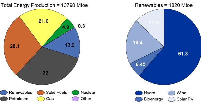
Renewable energy technologies are now a major global industry. Wind and solar PV have led recent growth in renewables-based capacity, though hydropower and bioenergy remain by far the largest source of supply [2]. In 2015, 1820 Mtoe of the 13790 Mtoe total energy production was covered by renewable technologies such as hydo, wind, solar and bio energy (Fig. 1).
Figure 1. Total energy production and the share of renewables in 2015.
Considering future targets, countries should increase the share of current renewable energies or implement new promising non-commercial renewable energies. In this regard, salinity gradient energy is a promising, renewable, sustainable and environmentally friendly alternative.
2. Salinity gradient energy
Salinity gradient energy (SGE) can be defined as mixing energy of two solutions with different salinity. In 1954, for the first time, Pattle remarked that the free mixing energy of sea and river water is equal to potential energy of 680 ft. high waterfall [4]. This untapped energy is available wherever a river meets with the sea. One of the earliest study, roughly estimated the theoretical SGE potential of equal amount of seawater/river water mixing energy as 2.43 TW by accounting
12
the total world river flow is 1.08 x 10⁶ m3/s [5]. A more recent study has reported only 57% of the 1.72 TW theoretical potential is technically available due to limitations associated with physical and technical characteristics [6]. A more detailed investigation by Alvarez-Silva et al. (2016) has indicated the extractable global potential of SGE gets decreased to 625 TWh/a when availability of the rivers, extraction factor, capacity factor were taken into consideration [7].
In theory, complete mixing of 1 m3 seawater (30 kg NaCl/m3) and 1 m3 river water (0 kg NaCl/m3) produces 1.7 MJ energy. This energy can be increased up to 6.1 MJ at 298 K when volumetric ratio of riverwater/sea water is 10 [8].
Mixing energy is available also in other sources than sea and river water. Some of them are; anthropogenic brines (salt mines, salt ponds, solar ponds, salt domes of oil wells or natural
gas wells), natural sources (hypersaline lakes), geothermal brines or brines of desalination units,
aqueous waste water with sufficient salinity,
thermolytic solutions (e.g. Ammonium bicarbonate).
Mixing solutions with a wide range of salinity generates different amount of energy. Fig. 2 illustrates the extractable Gibbs energy of mixing 1 m3 of diluted solution (0.1- 0.5 M NaCl) and 1 m3 of concentrated solution (0.5- 5.4 M NaCl) [9]. Mixing seawater (0.5 M NaCl) and saturated brine solution coming from membrane distillation (5.4 M NaCl) produces approximately 5 MJ energy where mixing seawater and brine solution coming from reverse osmosis (1 M NaCl) produces 0.25 MJ energy.
13
Figure 2. The theoretical Gibbs free energy of mixing for 1 m3 of NaCl solutions at 293 K [9]. 3. Theory
The theoretically available amount of energy obtainable from the controlled mixing of a concentrated salt solution and a diluted salt solution can be calculated from the Gibbs free energy.
c d
m
mix G G G
G
(1)
where ∆Gmix is the free energy of mixing (J·mol-1), Gm is the Gibbs energy of the mixture, the
brackish water (J·mol-1), G
c is the Gibbs energy of the concentrated salt solution (J·mol-1) and Gd
is the Gibbs energy of the diluted salt solution (J·mol-1).
The Gibbs energy of an ideal solution is the sum of chemical potentials of the individual chemical components present in that solution:
ini
14
In this equation, G is the Gibbs energy of the system (J·mol-1), µi is the chemical potential of
component i in the solution (J·mol-1), and n
i is the number of moles of component i in the solution.
The chemical potential of the component i in an ideal solution can be simplified when no pressure change or charge transport is considered upon mixing of a concentrated and a diluted salt solution:
i i i RT lnx 0 (3)
where µi0 is the molar free energy under standard conditions (J·mol-1), R is the universal gas
constant (8.314 J·(mol·K)-1), T is the absolute temperature (K), xi is the mol fraction of component
i. When Equation (3) is substituted in Equation (1) and n is replaced by solution concentration c (mol·m-3) and volume V (m3), the final Gibbs free energy of mixing can be described as follows:
i m i m m i d i d d i c i c c i mix c VRT x c V RT x c V RT x G , ln , , ln , , ln , (4)Harvesting salinity gradient energy is possible by several membrane based techniques; pressure-retarded osmosis (PRO) [10] and reverse electrodialysis (RED) [11] are the ones close to commercialization stage. Also technologies like capacitive mixing (CapMix) [12] and capacitive reverse electrodialysis (CRED) [13] are gaining attention recently.
Pressure retarded osmosis (PRO) works in an opposite way of reverse osmosis (RO). As in RO, a semi-permeable membrane that only allows the transport of the water and retains the salts were fed in between solutions with different salinity. Due to osmotic pressure water transport through to concentrated compartment and increase the pressure of the compartment. Kinetic energy of pressurized flow can be converted to electrical power by utilizing a turbine and a generator on the effluent of the concentrated solution flow[14,15].
15
Working principle of reverse electrodialysis (RED) is opposite of electrodialysis (ED). Both technology uses same orientation of alternated cation and anion exchange membrane which allows only transport of positive or negative charges (i.e. cation exchange membranes only let cations permeate and exclude anions). In RED electrochemical potential gradient drives ions from concentrated to diluted compartments. Created ionic flux can be converted to electricity by redox reactions at the electrode compartments in the end.
4. Reverse Electrodialysis
Salinity gradient energy can be harvested in a RED stack where ion exchange membranes were utilized, as demonstrated in Fig. 3. Creating a controlled mixing in a RED stack gives the opportunity to transfer the mixing energy directly to electricity. Alternate arrangement of cation exchange membranes (CEM) and anion exchange membranes (AEM) form the required compartment design for controlled mixing. When high and low concentration solutions are fed from neighboring compartments, electrochemical potential difference of the solutions drive the ions from high to low concentrations. However, only charges opposite to membrane fixed charge can diffuse through, i.e. for an ideal membrane only cations can transport through CEM. Therefore, an ionic flux can be generated inside of the stack. Ionic flux can be converted at the electrodes, by using for example a reversible redox reaction, to power an external electrical circuit [16].
Nernst equation allow is to calculate the membrane potential over an ion exchange membrane:
d c o a a zF RT V ln (5)
Where ΔVo is the theoretical membrane potential (V), R is the universal gas constant (8.314 J∙
16
membrane permselectivity (-), z is the electrochemical valance (-), ɑc is the activity of the
concentrated solution (mol∙l-1) and ɑ
d is the activity of the concentrated solution (mol∙l-1). Overall
stack potential can be calculated by adding up the individual membrane potentials.
Figure 3. Schematic of reverse electrodialysis.
Every component between two electrodes create a resistance against the transfer of the ions. A RED stack consist of cation exchange membranes, anion exchange membranes, spacers to create channels, high and low concentrated solutions, red-ox electrolyte solution and electrodes . Therefore all these components contribute as ohmic resistance of the stack. In addition to ohmic resistance, non-ohmic resistance is present due to concentration changes in bulk solutions and concentration change in the boundary layer. Rstack can be defined as [17];
17 ohmic non ohmic stack R R R (6)
where Rohmic is;
electrodes LCC LCC HCC HCC CEM AEM m ohmic R h h R R N R 2 2 1 1 2 (7)
in which RAEM and RCEM are the areal resistances of anion and cation exchange membrane (Ω∙m2),
respectively, h is the intermembrane distance (m), κ is the electrolyte conductivity (S∙m-1) and Relectrodes is the (ohmic) resistance of both electrodes and electrolyte compartments (Ω∙m2). The
spacer porosity ε, and the mask fraction β are dimensionless. Rnon-ohmic is;
BL C ohmic
non R R
R (8)
where RΔC is resistance due to the concentration change in the bulk solution (Ω∙m2) and RBL is
resistance due to concentration gradient (Ω∙m2).
The power can be estimated using Kirchoff’s law;
2 2 2 load stack load o load R R R V R I W (9)Here I is the current (A), Rload is the resistance of the load (Ω), Rstack is the stack resistance (Ω) and
V0 is the stack open circuit potential (V). When Rstack is equal to Rload maximum power can be
obtained analytically [18].
stack o R V W 4 2 max (10)18
Calculation of maximum power depends on open circuit voltage and Rstack. Therefore for the
optimization of RED, these two parameters and related parameters, i.e. permselectivity is related to OCV, must be considered.
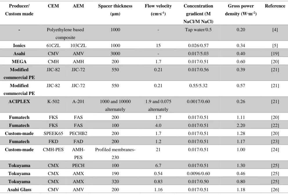
Several attempts have been made to extract the mixing energy of solutions in a RED stack. These studies have been conducted with different ion exchange membranes, feed solutions, spacers, operating conditions or number of cells. Table 1 shows the operating conditions, utilized materials and obtained gross power densities for several major studies in the literature. It can be pointed out, in seawater/river water mixing, compartment thickness had a great importance because produced energy is limited by the river water resistance. Importance of salinity ratio was also emphasized in Table 1. High salinity ratio increase the driving force on the ions and enhance the transport.
5. Challenges related to RED components
A RED stack unit compromise cation exchange membranes, anion exchange membranes, spacers, high concentration solution, low concentration solution, electrodes and electrolyte solution. Each component has critical duty in the stack and optimization of these components are possible.
5.1. Ion exchange membranes
A required medium for controlled transport of ions with opposite charges can be created by utilizing ion exchange membranes in RED. According to Strathmann (2014), high permselectivity, low electrical resistance, good mechanical and dimension stability, and high chemical stability are desired properties for an ion exchange membrane [35]. However, regarding the requirements of the process, aforementioned properties can differ. For example, due to milder solutions operated
19
Table 1. Operating conditions and power densities from the literature. Producer/
Custom made
CEM AEM Spacer thickness
(µm) Flow velocity (cm∙s-1) Concentration gradient (M NaCl/M NaCl) Gross power density (W∙m-2) Reference - Polyethylene based composite 1000 - Tap water/0.5 0.20 [4] Ionics 61CZL 103CZL 1000 15 0.026/0.57 0.34 [5] Asahi CMV AMV 3000 - 0.017/5.03 0.40 [19] MEGA CMH AMH 200 1.7 0.017/0.51 0.60 [20] Modified commercial PE JJC-82 JJC-72 550 0.21 0.017/0.56 0.39 [21] Modified commercial PE JJC-82 JJC-72 550 0.21 0.55/5.32 0.57 [21]
ACIPLEX K-502 A-201 1000 and 10000
alternately 1.9 and 0.075 alternately 0.0017/0.60 0.26 [21] Fumatech FKS FAS 200 1.7 0.017/0.51 1.11 [20] Fumatech FKS FAS 100 4.0 0.017/0.51 2.20 [22]
Custom-made SPEEK65 PECHB2 200 1.7 0.017/0.51 1.28 [20]
Fumatech FKD FAD 200 1.2 0.017/0.51 1.17 [23]
Custom-made CMH-PES
AMH-PES Profiled membranes-230 21 0.017/0.51 1.00 [24] Tokuyama CMX PECH 100 6.7 0.017/0.51 1.30 [25] Tokuyama CMX AMX 190 0.54 0.0096/0.60 0.46 [25] Tokuyama CMX AMX 320 0.83 0.017/0.50 0.80 [25]
20
Table 1. Operating conditions and power densities from the literature (Continued) Producer/
Custom made
CEM AEM Spacer thickness
(µm) Flow velocity (cm∙s-1) Concentration gradient (M NaCl/M NaCl) Gross power density (W∙m-2) Reference Fujifilm 80050 80045 270 0.62 0.50/5.40 2.4 [9] Fujifilm 80050 80045 270 0.41 0.50/4.0 1.06 [27] Neosepta CMS ACS 100 0.41 0.01/5.0 3.80 [28] Fujifilm 80050 80045 270 0.41 0.79/2.67 0.39 [29] Fujifilm 80050 80045 270 1.00 0.1/5.0 1.95 [30] Neosepta CMX AMX 200 0.12 0.01/2.40 1.86 [31]
Fumasep FAK-20 FAS-20 270 4.00 0.1/5.0 12.0 [32]
Fujifilm 80050 80045 270 1.00 0.03/4-5 2.70 [33]
21
in RED, membranes can be designed considering parameters that has crucial effect on power generation and cost of the produced electricity by RED [36,37]. For a RED ion exchange membrane, resistance and the permselectivity has a direct effect on generated power. Even though properties like swelling degree, ion exchange capacity and charge density seems as secondary, they are interrelated with resistance and permselectivity. Other than being interrelated, most of the parameters also have a counteracting relationship (e.g. swelling degree vs. permselectivity and resistance).
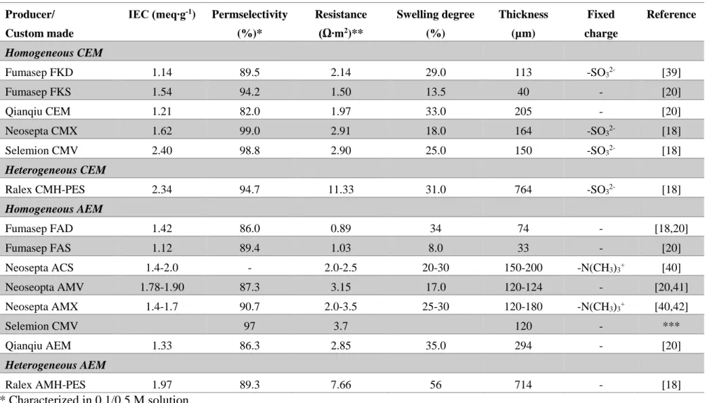
When eq. 5, 6, 7, 10 are investigated carefully, resistance and permselectivity can be concluded as performance determining parameters of ion exchange membranes. Table 2 tabulates the properties of some commercial ion exchange membranes tested in RED stack previously [38]. Permselectivity of commercial membranes vary from 86% to 99% where ideal value is 100%. On the other side, areal resistance has a broad range between 0.89 and 11.33 Ω∙m2.
5.1.1. Resistance
Heterogeneous ion exchange membranes are produced by mixing a charged resin and uncharged polymer. In order to have mechanically stable membrane films, thickness of these membranes are higher than homogenous membranes. Thickness together with having local uncharged regions across the membrane cause high areal resistance. Therefore, even though heterogeneous membranes have worthy permselectivity, utilizing them in RED results in low power density.
Most commonly, homogeneous ion exchange membranes are preferred in RED performance tests. Resistance range of these membranes are narrower (0.89-3.70 Ω∙m2). Up to date, the best performing membrane pairs for artificial sea and river water mixing were FKS and FAS provided by Fumatech (Germany). This performance was obtained for 100 µm spacer thickness at 4 cm∙s-1
22
Electrochemical properties of IEMs can be misleading because characterization conditions may not represent the process solutions accurately. Most common characterization solution for membrane resistance is 0.5 M NaCl while 0.1/0.5 M NaCl solutions are preferred for permselectivity. Membranes in RED, however, are exposed to a concentration gradient, in other words, both face of the membrane are in contact with different concentration. Concentration gradient can be 0.017/0.51 M NaCl (river water/seawater mixing) or 0.5/5.4 M NaCl (seawater/saturated brine mixing). Under these condition, membrane resistance and permselectivity differ from the measured value in 0.5 M NaCl or 0.1/0.5 M NaCl, respectively. Geise et al. (2014) characterized Selemion CMV and AMV membranes in a single concentration (1.0 M NaCl) and in a concentration gradient (0.01/1.0 M NaCl). CMV and AMV resistances measured 15 times and 13 times higher, respectively, when membranes were characterized in gradient solution instead of single solutions. Characterization in single solution for a 0.01-1.0 range also revealed that membrane resistance was dependent to solution concentration at a value lower than 0.5 M NaCl [43].
Dlugolecki et al. (2010) was also noted that at low solution concentrations (<0.1 M NaCl), very sharp increase of commercial AMX, CMX (Neosepta) and FAD, FKD (Fumatech) resistances were observed [44]. A detailed study on resistance of CMX membranes, covering 0.01 to 1.1 M NaCl solutions for single and concentration gradient experiments, was completed by Galama et al. (2014). In that study, 0.3 M NaCl was decided as a critical concentration where membrane resistance depends on external concentration [45].
23
Table 2. Properties of some commonly used ion exchange membranes Producer/
Custom made
IEC (meq∙g-1) Permselectivity (%)* Resistance (Ω∙m2)** Swelling degree (%) Thickness (µm) Fixed charge Reference Homogeneous CEM Fumasep FKD 1.14 89.5 2.14 29.0 113 -SO32- [39] Fumasep FKS 1.54 94.2 1.50 13.5 40 - [20] Qianqiu CEM 1.21 82.0 1.97 33.0 205 - [20] Neosepta CMX 1.62 99.0 2.91 18.0 164 -SO32- [18] Selemion CMV 2.40 98.8 2.90 25.0 150 -SO32- [18] Heterogeneous CEM
Ralex CMH-PES 2.34 94.7 11.33 31.0 764 -SO32- [18]
Homogeneous AEM Fumasep FAD 1.42 86.0 0.89 34 74 - [18,20] Fumasep FAS 1.12 89.4 1.03 8.0 33 - [20] Neosepta ACS 1.4-2.0 - 2.0-2.5 20-30 150-200 -N(CH3)3+ [40] Neoseopta AMV 1.78-1.90 87.3 3.15 17.0 120-124 - [20,41] Neosepta AMX 1.4-1.7 90.7 2.0-3.5 25-30 120-180 -N(CH3)3+ [40,42] Selemion CMV 97 3.7 120 - *** Qianqiu AEM 1.33 86.3 2.85 35.0 294 - [20] Heterogeneous AEM Ralex AMH-PES 1.97 89.3 7.66 56 714 - [18] * Characterized in 0.1/0.5 M solution. ** Characterized in 0.5 M NaCl solution. ***Information from manufacturer.
24
Areal solution resistance values was converted from the conductivity values by using Eq. 11 from Galama’s study (2016) while CMX and AMX resistance used as it is [46] ;
A L
Rsolution (11)
Where Rsolution is solution resistance (Ω), ρ is the solution specific resistivity (Ω∙cm), L is the
thickness (cm), A is the area (cm2) [30].
Depending on the process conditions, ion exchange membrane resistances can be important. Fig. 4 compares the areal resistances of commercial AMX and CMX in different NaCl concentration with the corresponding areal solution resistance where compartment thickness is 270 µm. In low concentration, up to 0.05 M NaCl, solution resistance is higher than the membranes’. After 0.1 M NaCl solutions membrane resistance remain constant and solution resistance decreases. As a result, seawater/river water mixing in RED is limited by river water resistance. Improving membrane conductivity cannot enhance produced power significantly. On the other hand, power generation is limited by membrane resistance in case of seawater/brine mixing.
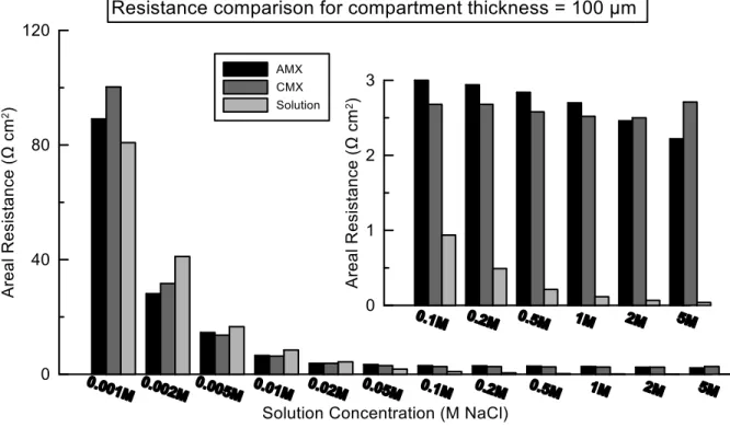
Reducing compartment thickness reduces the dominant effect of low concentration compartment on total resistance. In Fig. 5, CMX, AMX and solution areal resistances are compared for 100 µm compartment thickness. For this case membrane and compartment resistance are comparable starting from really low concentration (i.e. 0.001 M NaCl).
25
Figure 4. Areal resistance of the solutions, AMX and CMX. 270 µm compartment thickness was assumed for calculation of solution.
Fig. 4 and 5 encourage preparing IEMs designed especially for RED application and for desired process conditions. The comparison also indicates that there is a possibility for membrane engineering to reduce the membrane resistance and generate more energy in return, for the processes where total resistance is dominated by IEMs. Since resistance is proportional to the thickness, reducing membrane thickness can be an opportunity to get benefit from such processes. Considering, also, mechanical properties is related to the thickness, an optimization can be conducted. An alternative to thinner membranes can be a thin active layer membranes with same thickness. Creating dense thin layer that maintain the permselectivity and a porous support that enhance the conductivity can answer the needs of the RED.
26
Figure 5. Areal resistance of the solutions, AMX and CMX. 100 µm compartment thickness was assumed for calculation of solution.
Another challenge related to membrane resistance is the mixing solution contains more than NaCl. Most of the RED study so far has been run for the artificial solutions mimicked by NaCl [22,26,28,36]. However, natural solutions are more complex. For example, average real seawater contains 10% of other ions (e.g. Mg2+ and SO42-) [47]. There are several attempts evaluated the
effect of other ions or natural solutions [27,33,48–50]. Evaluation the effect of Mg2+, which is
second highest cation in the seawater, for seawater/brine mixing revealed that power reduction was strongly related to increase of the CEM resistance in presence of magnesium [27]. Fig. 6 illustrates the relation between magnesium concentration and IEMs. Introduction of 10% of MgCl2
to the solution (0.5 m NaCl solutions were used for the characterization) resulted in a 3 times higher total CEM resistance, while effect on AEM was insignificant. This drastic effect can be explained by the affinity of the ions. Mg2+ has higher affinity to the fixed charged groups (i.e.-SO32-) than Na+ [35]. Due to this high affinity, Mg2+ is preferentially selected by the fixed groups
27
of the membrane and dissociate slower than the Na+ ions [51]. High affinity and slow dissociation cause charge screening or partial neutralization of charged groups. Ultimately, condensation of counter-ion/fixed-charge pairs takes place, and cause a higher membrane resistance.
Figure 6. Resistances of membrane (Rm), diffusion boundary layer (RDBL), and electric double layer (REDL) at increasing MgCl2 content for: a) Fuji-CEM-80050 cation exchange membrane; b)
Fuji-AEM-80045 anion exchange membrane [27].
One strategy to avoid charge screening can be coating the membrane surface with a very thin layer of charges opposite to the fixed charge sign [52]. This thin layer can prevent Mg2+ penetration through the membrane electrostatically. Moreover, because sodium has smaller hydration radius than magnesium, the extra layer create less resistant to sodium ion. Though, the possibility of increasing the resistance due to extra layer must be considered carefully.
5.1.2. Permselectivity
Permselectivity indicates ability to select counter ions over co-ions. Most of the commercial ion exchange membranes has permselectivity higher than 90% while ideal permselectivity is 100%. Although membranes are close to ideal value in characterization solution (0.1/0.5 M NaCl), more realistic process solutions or having different concentrations can alter the permselectivity.
28
Previous studies showed that permselectivity of a membrane strongly related to concentration of test solutions. Membranes tested in diluted environment resulted in with a permselectivity close to ideal [30,53,54]. Hosseini et al. (2012) measured the permselectivity of the heterogeneous Ralex CMH and AMH membranes in 0.01/0.1, 0.05/0.5, 0.1/1.0 M NaCl by keeping the molar ratio at a constant value 10. AMH permselectivity showed a clear decrease by increasing salt content while insignificant effect was observed on CMH. Moreover, for 0.01/0.1 M, having Ba2+ reduced CEM permselectivity from %91.2 to %65.2 while having SO42- reduced it from 84.8% to 43.0% [54].
Similarly, Fontananova et al. (2017) observed a sharp reduction on AEM800 provided by Fujifilm when using 0.5/4 M NaCl for characterization; from 0.93 to 0.68. Furthermore, it reduced to 50% in case 0.473 M NaCl+0.014 M MgCl2/3.78 M NaCl+0.11 M MgCl2 used [30]. Due to divalent
ions form stronger bonds, it has a screening effect on polymer fixed charge as it is explained earlier. Therefore, charge density get reduced, so permselectivity. One strategy to overcome this problem can be preparing monovalent selective membranes. Preparation of monovalent selective membranes can be based on the different affinity, hydration radius or electrostatic interaction.
Counter acting effect of membrane properties makes membrane optimization a difficult process. In addition, membrane properties differ depending on concentration and content of ions. Therefore, producing a membrane that can work for all conditions is not possible. Trade-offs and process conditions must be taken into account during the optimization of the RED membranes.
5.2. Spacers
High and low concentration compartments in a RED stack is provided by equipped spacers between cation and anion exchange membranes. They also act as a turbulent flow promoter owing to their meshed geometry.
29
Total stack resistance is the sum of the resistance of every single component (see eq. 7). In RED processes that is fed with low concentration solutions (<0.3 M NaCl), power production is limited by the low compartment resistance. Since compartment thickness is decided by the spacers, their effect on produced power is significant.
A straightforward strategy to reduce stack resistance and increase gross power density is using thin spacers. Following this strategy, Vermaas et al. (2011) was successful to double the gross power density when using 100 µm thick spacers. On the other hand, when thickness is further reduced to 60 µm, flow rate could only be increased up to some extend because of high shear stress. Moreover, lowering the thickness increased the pump energy loss and reduced the net power density [22].
In a RED stack, after piling up membranes and spacer they are replaced and pressed from both side so feeds cannot leak from the loose parts. In this kind of arrangement spacers contact to membranes and cover a specific area of the membrane depending on their opening. Therefore, ion transport can only occur from the open area. This phenomena is called as “shadow effect” in the literature. There were several attempts to reduce the shadow effect. Dlugolecki et al. (2010) used ion conductive spacers made by cutting CMX and AMX membrane to the desired shape. Ion conductive spacers were compared with non-conductive spacers which has same open area (54%), porosity (73%) and thickness 0.32 mm. Due to enhancement in the conductive medium and reduction in the concentration polarization, 3-4 times higher power density was obtained when ion conductive spacers were used [55].
Spacerless design for RED was suggested by Vermaas et al. (2011) in order to overcome so called shadow effect. On top of one side of the membranes, heterogeneous membranes were hot pressed and desired profiles were formed at 230-245 µm thickness. RED experiments revealed that ohmic
30
resistance was reduced while non-ohmic resistance was increased in return. Therefore, expected improvement on power could not be achieved [56]. Yet, other attempts with different profile geometry had some achievements [25,57].
5.3. Electrode and electrolyte solution
In a RED stack, electrode compartments are placed at the end of the membrane pile. It consist an anode, a cathode and recirculating electrolyte solution. Most of the time, electrode compartments are separated from inner compartments carefully considering environmental risks. To avoid a possible leakage from electrolyte solution to discharged RED effluents a special membrane (i.e. Nafion) [58] or 2 same kind of ion exchange membranes [59] are used in between. Scialdione et al. (2012) reported that perfluoronated Nafion was impermeable to redox couple while Selemion anionic membranes allowed very slow transport of redox couple to the neighboring compartment [58].
There are a few study that investigated electrodes and electrolyte solutions particularly in RED [58–61]. Lee et al. (2016) prepared a Vulcan coated graphite electrode that resulted in less resistance than the Ir-coated titanium mesh, Pt-coated titanium plate and graphite foil. Lowering electrode resistance helped to increase power density by 5-10%. It is also noted hexacyanoferrate(III) and hexacyanoferrate(II) as redox couple with 1 M Na2SO4 showed good
reversibility. It is also stated using Na2SO4 and Vulcan coated graphite can lower the capital and
operational cost [61]. Burheim et al. (2012) tested different red-ox salts and electrode material. They concluded mass transfer in the electrolyte controlled the electrochemical reactions. Therefore, replacing cheap electrodes (i.e. graphite) can be possible [60].
31 6. Conclusion
Reverse elecrtodialysis is a developing, membrane based, renewable and environmentally friendly technology. The purpose of introduction chapter, was to give a general sense about the theory behind the RED, achievements so far and challenges related to the RED component.
The maximum gross power for artificial seawater/river water mixing was obtained as 2.2 W∙m-2,
up to date [22]. This chapter showed the power density can be increased by some straightforward modification on the membrane components easily (i.e. decreasing thickness of low concentration compartment). It was also noted, membrane components must be design by taking process conditions into account. On the other hand, it was underlined that results reported with artificial solution do not represent the real performance of the RED. In more realistic solutions, electrochemical properties (e.g. permselectivity, resistance) differ significantly from the characterization values.
Due to counteracting behavior of ion exchange membrane properties, optimization of the RED is quite challenging. But, this counter acting effect also gives an opportunity to optimize the properties, for the sake of RED.
32 7. References
[1] U.S. Energy Information Administration, International Energy Outlook 2016, Washington, USA, 2016.
[2] International Energy Agency, World Energy Outlook 2016, Paris, France, 2016.
[3] European Comission, Communication from the commission to the European parliament, the council, the European economic and social committee and thecommittee of the regions, Brussels, Belgium, 2011.
[4] R.E. Pattle, Production of electric power by mixing fresh and salt water in the hydroelectric pile, Nature. 174
[5] J.N. Weinstein, F.B. Leitz, Electric Power from Differences in Salinity: The Dialytic Battery, Science, 191 (1976) 557–559.
[6] J. Kuleszo, C. Kroeze, J. Post, B.M. Fekete, The potential of blue energy for reducing emissions of CO2 and non-CO2 greenhouse gases, J. Integr. Environ. Sci. 7 (2010) 89–96.
[7] O.A. Alvarez-Silva, A.F. Osorio, C. Winter, Practical global salinity gradient energy potential, Renew. Sustain. Energy Rev. 60 (2016) 1387–1395.
[8] J. Veerman, M. Saakes, S.J. Metz, G.J. Harmsen, Reverse electrodialysis: Performance of a stack with 50 cells on the mixing of sea and river water, J. Memb. Sci. 327 (2009) 136– 144.
[9] R.A. Tufa, E. Curcio, E. Brauns, W. van Baak, E. Fontananova, G. Di Profio, Membrane distillation and reverse electrodialysis for near-zero liquid discharge and low energy seawater desalination, J. Memb. Sci. 496 (2015) 325–333.
[10] F. Helfer, C. Lemckert, Y.G. Anissimov, Osmotic power with pressure retarded osmosis : theory , performance and trends – a review, J. Memb. Sci. 453 (2014) 337–358.
[11] N.Y. Yip, D.A. Vermaas, K. Nijmeijer, M. Elimelech, Thermodynamic, energy efficiency, and power density analysis of reverse electrodialysis power generation with natural salinity gradients, Environ. Sci. Technol. 48 (2014) 4925-4936.
[12] R.A. Rica, R. Ziano, D. Salerno, F. Mantegazza, R. van Roij, D. Brogioli, Capacitive mixing for harvesting the free energy of solutions at different concentrations, Entropy, 15 (2013) 1388–1407.
[13] D.A. Vermaas, S. Bajracharya, B. Sales, M. Saakes, Environmental science clean energy generation using capacitive electrodes in reverse electrodialysis, Energy Environ. Sci. 6 (2013) 643–651.
[14] S. Loeb, Production of energy from concentrated brines by pressure-retarded osmosis I. preliminary technical and economic correlations, J. Memb. Sci. 1 (1976) 49–63.
[15] K. Gerstandt, K. Peinemann, S. Erik, T. Thorsen, T. Holt, Membrane processes in energy supply for an osmotic power plant, Desalination. 224 (2008) 64–70.
33
[16] J.W. Post, J. Veerman, H.V.M. Hamelers, G.J.W. Euverink, S.J. Metz, K. Nymeijer, C.J.N. Buisman, Salinity-gradient power: Evaluation of pressure-retarded osmosis and reverse electrodialysis, J. Memb. Sci. 288 (2007) 218–230.
[17] D. a. Vermaas, E. Guler, M. Saakes, K. Nijmeijer, Theoretical power density from salinity gradients using reverse electrodialysis, Energy Procedia. 20 (2012) 170–184.
[18] P. Dlugolecki, K. Nymeijer, S. Metz, M. Wessling, Current status of ion exchange membranes for power generation from salinity gradients, J. Memb. Sci. 319 (2008) 214– 222.
[19] R. Audinos, Electrodialyse inverse. Etude de l’energie electrique obtenue a partir de deux solutions de salinites differentes, J. Power Sources. 10 (1983) 203–217.
[20] E. Güler, R. Elizen, D. a. Vermaas, M. Saakes, K. Nijmeijer, Performance-determining membrane properties in reverse electrodialysis, J. Memb. Sci. 446 (2013) 266–276. [21] J. Jagur-Grodzinski, R. Kramer, Novel process for direct conversion of free energy of
mixing into electric power, Ind. Eng. Chem. Process Des. Dev. 25 (1986) 443–449. [22] D.A. Vermaas, M. Saakes, K. Nijmeijer, Doubled power density from salinity gradients at
reduced intermembrane distance., Environ. Sci. Technol. 45 (2011) 2010–2011.
[23] J. Veerman, R.M. de Jong, M. Saakes, S.J. Metz, G.J. Harmsen, Reverse electrodialysis: Comparison of six commercial membrane pairs on the thermodynamic efficiency and power density, J. Memb. Sci. 343 (2009) 7–15.
[24] D.A. Vermaas, M. Saakes, K. Nijmeijer, Enhanced mixing in the diffusive boundary layer for energy generation in reverse electrodialysis, J. Memb. Sci. 453 (2014) 312–319. [25] E. Güler, R. Elizen, M. Saakes, K. Nijmeijer, Micro-structured membranes for electricity
generation by reverse electrodialysis, J. Memb. Sci. 458 (2014) 136–148.
[26] J. Veerman, M. Saakes, S.J. Metz, G.J. Harmsen, Electrical power from sea and river water by reverse electrodialysis: a first step from the laboratory to a real power plant, Environ. Sci. Technol. 44 (2010) 9207–12.
[27] A.H. Avci, P. Sarkar, R.A. Tufa, D. Messana, P. Argurio, E. Fontananova, G. Di, E. Curcio, Effect of Mg2+ ions on energy generation by Reverse Electrodialysis, 520 (2016) 499–506. [28] A. Daniilidis, D.A. Vermaas, R. Herber, K. Nijmeijer, Experimentally obtainable energy
from mixing river water, seawater or brines with reverse electrodialysis, Renew. Energy. 64 (2014) 123–131.
[29] E. Farrell, M.I. Hassan, R.A. Tufa, A. Tuomiranta, A.H. Avci, A. Politano, E. Curcio, H.A. Arafat, Reverse electrodialysis powered greenhouse concept for water- and energy-self-sufficient agriculture, Appl. Energy. 187 (2017) 390–409.
[30] E. Fontananova, D. Messana, R.A. Tufa, I. Nicotera, V. Kosma, E. Curcio, W. Van Baak, E. Drioli, G. Di Profio, Effect of solution concentration and composition on the electrochemical properties of ion exchange membranes for energy conversion, J. Power Sources. 340 (2017) 282–293.
34
[31] K. Kwon, J. Han, B.H. Park, Y. Shin, D. Kim, Brine recovery using reverse electrodialysis in membrane-based desalination processes, Desalination. 362 (2015) 1–10.
[32] M. Tedesco, E. Brauns, A. Cipollina, G. Micale, P. Modica, G. Russo, J. Helsen, Reverse Electrodialysis with saline waters and concentrated brines: a laboratory investigation towards technology scale-up, J. Memb. Sci. 492 (2015) 9–20.
[33] M. Tedesco, C. Scalici, D. Vaccari, A. Cipollina, A. Tamburini, G. Micale, Performance of the first Reverse Electrodialysis pilot plant for power production from saline waters and concentrated brines, J. Memb. Sci. 500 (2015) 33–45.
[34] M. Turek, B. Bandura, P. Dydo, Power production from coal-mine brine utilizing reversed electrodialysis, Desalination. 221 (2008) 462–466.
[35] H. Strathmann, Ion-Exchange Membrane Separation Processes, Elsevier, Amsterdam, The Netherlands, 2004.
[36] E. Guler, Y. Zhang, M. Saakes, K. Nijmeijer, Tailor-made anion-exchange membranes for salinity gradient power generation using reverse electrodialysis, ChemSusChem. 5 (2012) 2262–2270.
[37] J.W. Post, C.H. Goeting, J. Valk, S. Goinga, J. Veerman, H.V.M. Hamelers, P.J.F.M. Hack, Towards implementation of reverse electrodialysis for power generation from salinity gradients, Desalin. Water Treat. 16 (2010) 182–193.
[38] J.G. Hong, B. Zhang, S. Glabman, N. Uzal, X. Dou, H. Zhang, X. Wei, Y. Chen, Potential ion exchange membranes and system performance in reverse electrodialysis for power generation: A review, J. Memb. Sci. 486 (2015) 71–88.
[39] P. Długołecki, A. Gambier, K. Nymeijer, M. Wessling, Practical potential of reverse electrodialysis as process for sustainable energy generation, Environ. Sci. Technol. 43 (2009) 6888–6894.
[40] A. Elattar, A. Elmidaoui, N. Pismenskaia, C. Gavach, G. Pourcelly, Comparison of transport properties of monovalent anions through anion-exchange membranes, J. Memb. Sci. 143 (1998) 249-261.
[41] R.K. Nagarale, G.S. Gohil, V.K. Shahi, Recent developments on ion-exchange membranes and electro-membrane processes, Adv. Colloid Interface Sci. 119 (2006) 97–130.
[42] E. Volodina, N. Pismenskaya, V. Nikonenko, C. Larchet, G. Pourcelly, Ion transfer across ion-exchange membranes with homogeneous and heterogeneous surfaces, 285 (2005) 247– 258.
[43] M. Geise, A.J. Curtis, M.C. Hatzell, M.A Hickner, B.E. Logan, Salt concentration differences alter membrane resistance in reverse electrodialysis stacks, Environ. Sci. Technol. Lett. 1 (2014) 36–39.
[44] P. Długołęcki, B. Anet, S.J. Metz, K. Nijmeijer, M. Wessling, Transport limitations in ion exchange membranes at low salt concentrations, J. Memb. Sci. 346 (2010) 163–171. [45] A.H. Galama, D.A. Vermaas, J. Veerman, M. Saakes, H.H.M. Rijnaarts, J.W. Post, K.
35
Nijmeijer, Membrane resistance: The effect of salinity gradients over a cation exchange membrane, J. Memb. Sci. 467 (2014) 279–291.
[46] A.H. Galama, N.A. Hoog, D.R. Yntema, Method for determining ion exchange membrane resistance for electrodialysis systems, Desalination. 380 (2016) 1–11.
[47] M. Kennish, (2001), Practical Handbook of Marine Science, 3th ed., Boca Raton, Florida, CRC Press
[48] D.A. Vermaas, J. Veerman, M. Saakes, K. Nijmeijer, Influence of multivalent ions on renewable energy generation in reverse electrodialysis, Energy Environ. Sci. 7 (2014) 1434. [49] R.A. Tufa, E. Curcio, W. van Baak, J. Veerman, S. Grasman, E. Fontananova, G. Di Profio,
Potential of brackish water and brine for energy generation by salinity gradient power-reverse electrodialysis (SGP-RE), RSC Adv. 4 (2014) 42617–42623.
[50] J.W. Post, H.V.M. Hamelers, C.J.N. Buisman, Influence of multivalent ions on power production from mixing salt and fresh water with a reverse electrodialysis system, J. Memb. Sci. 330 (2009) 65–72.
[51] G.M. Geise, H.J. Cassady, D.R. Paul, B.E. Logan, M.A. Hickner, Specific ion effects on membrane potential and the permselectivity of ion exchange membranes, Phys. Chem. Chem. Phys. 16 (2014) 21673–21681.
[52] E. Güler, W. van Baak, M. Saakes, K. Nijmeijer, Monovalent-ion-selective membranes for reverse electrodialysis, J. Memb. Sci. 455 (2014) 254–270.
[53] A. Zlotorowicz, R. V Strand, O.S. Burheim, S. Kjelstrup, The permselectivity and water transference number of ion exchange membranes in reverse electrodialysis, J. Memb. Sci. 523 (2017) 402–408.
[54] S.M. Hosseini, S.S. Madaeni, A.R. Khodabakhshi, The electrochemical characterization of ion exchange membranes in different electrolytic environments: Investigation of concentration and pH effects, Sep. Sci. Technol. 47 (2012) 455–462.
[55] P. Długołęcki, J. Dąbrowska, K. Nijmeijer, M. Wessling, Ion conductive spacers for increased power generation in reverse electrodialysis, J. Memb. Sci. 347 (2010) 101–107. [56] D.A. Vermaas, M. Saakes, K. Nijmeijer, Power generation using profiled membranes in
reverse electrodialysis, J. Memb. Sci. 385–386 (2011) 234–242.
[57] S. Pawlowski, T. Rijnaarts, M. Saakes, K. Nijmeijer, J.G. Crespo, Improved fluid mixing and power density in reverse electrodialysis stacks with chevron-profiled membranes, 531 (2017) 111–121.
[58] O. Scialdone, C. Guarisco, S. Grispo, a. D. Angelo, a. Galia, Investigation of electrode material – Redox couple systems for reverse electrodialysis processes. Part I: Iron redox couples, J. Electroanal. Chem. 681 (2012) 66–75.
[59] J. Veerman, M. Saakes, S.J. Metz, G.J. Harmsen, Reverse electrodialysis: Evaluation of suitable electrode systems, J. Appl. Electrochem. 40 (2010) 1461–1474.
36
electro-dialysis and electro-dialysis, Desalination. 285 (2012) 147–152.
[61] S.Y. Lee, Y.J. Jeong, S.R. Chae, K.H. Yeon, Y. Lee, C.S. Kim, N.J. Jeong, J.S. Park, Porous carbon-coated graphite electrodes for energy production from salinity gradient using reverse electrodialysis, J. Phys. Chem. Solids. 91 (2016) 34–40.
37
CHAPTER 2:
REVERSE ELECTRODIALYSIS PERFORMANCE FOR
RIVER WATER/SEAWATER MIXING
Abstract
The effectiveness of Salinity Gradient Power - Reverse Electrodialysis (SGP-RE) in real practice is still not clearly defined due to the lack of specific studies in literature, being investigations in large part limited to on pure NaCl solutions or aqueous mixtures of two salts. In this work, we experimentally assessed the impact of natural feed streams (collected from Licetto river and Tyrrenian sea in Amantea - Italy) in terms of Open Circuit Voltage (OCV) and power density (Pd)
measured on lab-scale SGP-RE stack prototype; results have been compared to those obtained when using NaCl solutions having equivalent ionic strength. Highest OCV (3.68 V and 4.09 V) and Pd values (0.46 and 1.41 W∙m-2) were observed at temperature of 60°C for real and synthetic
feeds, respectively.
The extent of electrical resistances (ion exchange membrane/electrical double layer/diffusion boundary layer) was elucidated by electrochemical impedance spectroscopy (EIS); in particular, a critical effect of real solution on cation exchange membrane (CEM) resistance was detected. In addition, ionic characterization of process effluents revealed the occurrence of uphill transport of multivalent ions Mg2+, Ca2+ and SO42-.
38 1. Introduction
According to US Energy Information Administration, world net electricity generation is expected to increase from 20 trillion to 40 trillion kWh in the coming 30 years; among all sources which presently fulfill the increasing demand of energy, renewable energy is the fastest-growing source of electric power with an annual 2.8% increase [1]. An emerging renewable energy source is Salinity Gradient Power (SGP), originally proposed for sea and river water mixingmore than 60 years ago [2]. The total technical potential of SGP is estimated to be around 647 GW, which is 23% of the global electricity consumption [3]. Possible application areas of SGP techniques are estuaries where freshwater rivers run into seawater [4–7], high salinity wastewater (brine from desalination [8–11] or salt mining and saltworks [12–14]) and saltwater lakes [15,16].
There are two common technologies which harvest SGP by utilizing membrane-based processes: Reverse Electrodialysis (RE) – object of the present work - and Pressure Retarded Osmosis (PRO) [17]. In a typical SGP-RE system, cation exchange membranes (CEM) and anion exchange membranes (AEM) are piled up alternately between cathode and anode (Fig. 1). CEMs and AEMs are separated by spacers to allow the diluted and concentrated salt solutions flow through. Due to salinity gradient across the membranes, ions diffuse through the membranes from High Concentration Compartment (HCC) to Low Concentration Compartment (LCC): the ionic flux is converted to electronic flux in the electrode compartments by reduction and oxidation reactions on the electrode surface [10].
39
Figure 1. Conceptual scheme of a SGP-RE Unit
The most abundant natural salinity gradient sources are seawater and river water. Theoretically, the generated mixing energy of two solution with different concentration can be calculated by Gibbs free energy equation [6]:
M C C C M D D D mix C C C V C C C V RT G 2 ln ln (1) C D C C D D M V V C V C V C (2)
40
concentration CD, VC is volume of concentrated solution with concentration CC, CM is the
concentration of mixed solution, R is the gas constant (R=8.31432 Jmol-1K-1) and T is the
temperature (K). Eq. 1 assumes entropy change in the water and activity of the solutions having negligible effect on final ΔGmix.
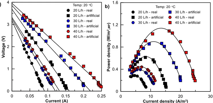
In theory, complete mixing of 1 m3 seawater (assumed as 30 kg ∙m-3 NaCl) and 1 m3 river water (assumed as pure water) produces 1.7 MJ energy, that can be increased up to 6.1 MJ at 298 K when volumetric ratio of river water/seawater is 10 [6]. The numerous attempts made to investigate extractable energy of seawater and river water mixing resulted in gross power density between 0.20 - 2.2 W∙m-2 depending on membrane type, spacer type, spacer thickness, membrane area, number of cells, linear flow velocity, slight difference on concentration gradient and temperature [2,18–27,7,28]. One of the first measurements of power density was reported as 0.20 W∙m-2 by Pattle (1954). In that study, maximum power was obtained for polyethylene mixed with crosslinked polystyrene resins membranes and 1 mm nonconductive thickness at 39oC where 0.5 M NaCl solution and tap water were used as feed [2]. After IEM technology had improved, Veerman et al. (2009) performed synthetic seawater/river water RE experiments with six commercial membranes pairs; the highest measured power densities were 1.17 and 1.18 W∙m-2 for
Fumasep (FAD and FDK) and Selemion (AMV and CMV) membrane pairs, respectively, and a noteworthy thermodynamic efficiency (35%) was obtained [25]. Guler et al. (2013) prepared custom-made sulfonated polyetheretherketone CEM and polyepichlorohydrin AEM designed for RE; utilizing these membrane pairs resulted in 1.28 W∙m-2 gross power density [20]. Hong et al.
(2014) conducted RE experiments by pairing a custom-made composite CEM with ASV (Selemion, Japan) AEM; under optimized electrochemical properties, a maximum power density of 1.3 W∙m-2 was generated [21]. Vermaas et al. (2011) investigated the effect of intermembrane
![Figure 2. The theoretical Gibbs free energy of mixing for 1 m 3 of NaCl solutions at 293 K [9]](https://thumb-eu.123doks.com/thumbv2/123dokorg/2869042.9242/19.918.261.653.108.479/figure-theoretical-gibbs-free-energy-mixing-nacl-solutions.webp)