ALMA MATER STUDIORUM
UNIVERSIT `
A DI BOLOGNA
Scuola di Ingegneria e Architettura
Campus di Cesena
Corso di Laurea Magistrale in Ingegneria e Scienze Informatiche
DESIGN AND DEVELOPMENT
OF A UNITY BASED FRAMEWORK
FOR AUGMENTED WORLDS
Elaborata nel corso di: Programmazione Avanzata e Paradigmi
Tesi di Laurea di:
PIERLUIGI MONTAGNA
Relatore:
Prof. ALESSANDRO RICCI
Co-relatori:
Dott. ANGELO CROATTI
ANNO ACCADEMICO 2015 - 2016
SESSIONE I
Keywords:
Mixed-Reality
Augmented World
Unity
Hologram
To my beloved aunt,
family and friends,
whose words encourage me
every day . . .
Abstract
EN The way we’ve always envisioned computer programs is slowly changing. Thanks to the recent development of wearable technologies we’re experiencing the birth of new applications that are no more limited to a fixed screen, but are instead sparse in our surroundings by means of fully fledged computational objects. In this paper we discuss proper techniques and technologies to be used for the creation of “Augmented Worlds”, through the design and development of a novel framework that can help us understand how to build these new programs.
IT Il modo in cui abbiamo sempre concepito i programmi sta lentamente cam-biando. Grazie allo sviluppo delle recenti tecnologie wearable stiamo assitendo alla nascita di nuove applicazioni che non sono pi`u limitate ad uno schermo fisso, ma sono invece disperse all’interno dell’ambiente, aumentandone le caratteristiche per via di una serie di oggetti virtuali. In questo documento vogliamo analizzare quali tecniche e tecnologie utilizzare per la creazione di “mondi aumentati”, attraverso lo sviluppo di un framework che possa aiutarci a comprendere meglio i diversi punti di vista legati alla creazione di questi nuovi e innovativi programmi.
Contents
1 Introduction 1
2 Augmented World 3
2.1 Main concepts . . . 5
2.2 Towards a programming model . . . 6
3 Envisioning the framework 9 3.1 Goals . . . 9
3.2 Topsight of the system . . . 10
3.3 Hologram . . . 12
3.4 HoloDoer . . . 14
3.5 User modeling and interaction . . . 15
4 The Unity Game Engine 19 4.1 Basics . . . 19
4.2 Component based development . . . 21
4.3 Runtime Engine Overview . . . 21
4.4 Vuforia support . . . 24
4.5 The High Level API (HLAPI) . . . 26
4.6 Editor extension . . . 30 5 Development 33 5.1 Hologram . . . 33 5.1.1 View . . . 36 5.1.2 Model . . . 37 5.1.3 Network Synchronization . . . 37
5.2 User shape and interaction . . . 43
5.3 Mono Event System . . . 46
5.4 HoloDoer . . . 47
5.5 Tracking Area . . . 48
CONTENTS CONTENTS
5.7 The problem of serialization . . . 50
6 Using the framework 51 6.1 Creating the scene . . . 51
6.2 Simple Cube Example . . . 53
6.3 Tracking Area Example . . . 64
6.4 Building and testing . . . 71
6.5 Reposiory . . . 72
7 Wrapping things up 73 7.1 State of the art of technology . . . 73
7.2 Why a framework? . . . 75
7.3 The future . . . 76
Chapter 1
Introduction
If computing companies have their way, 2016 will be the year in which aug-mented and virtual reality become widely popular. Different firms such as Face-book, Sony and Microsoft are getting ready to launch their set of high tech wear-ables. Google and Qualcomm are hard working on area learning, using computer vision technologies. Meta is ready to launch his new headset and is finding new ways to have a more natural interaction with holographic entities. Looks like we’ve finally reached a point that not so long ago we envisioned only in sci-fi movies.
What these new technologies seems to have in common is the usage of some sort of headset that, being equipped with different types of sensors, is able to alter the user perception of the world. This headset can either display new information on top of what the user is already seeing, in which case we talk about Augmented Reality, or render a new world entirely in front of his eyes; we call this Virtual Reality.
Virtual Reality is fully immersive: the headset must, by necessity, block out the external world. Using stereoscopy, a technique that fools the brain into creating the illusion of depth, it transforms a pair of images into a single experience of a fully three-dimensional world. At the moment, main examples of VR technology are Facebook’s Oculus Rift[1] and HTC’s Vive[2], and their primary business is the gaming industry.
Augmented Reality on the other hand, must maintain its user connected with the real world, allowing heads-up displays to be used instead of a closed headset. It makes use of interest points, fiducial markers or optical flows in the camera images to find the right way to overlay digital content on top of a video stream. Even though AR is nowadays mainstream and widely used inside mobile applications, we are intrigued by the possibilities brought by this technology, as recently seen with the debut of Microsoft’s Hololens[3], that aims to liberate computing from a fixed screen, overlaying its user with useful additions inside his environment.
1. Introduction
(a) Microsoft Hololens
(b) HTC Vive
Figure 1.1: Figure 7.3c shows an headset with see-trough lens. Figure 7.3d is a closed headset for virtual reality, provided with special gears to track movements in a closed fixed space.
of real-time applications that place the user in-between the virtual and physical world. As technology is moving forward, new programming scenarios open of which we need to find ways to meaningfully encapsulate their complexity, for developers to build new systems.
In this document we are going design, implement and use a novel programming framework for Augmented Worlds. Each chapter is part of a process that wants to extend the knowledge of what is on top of the model.
The first chapter is about what defines an Augmented World, describing the model through a list of its related concepts. Here we analyze critical points required for a software stack usable for the creation of these applications, while arguing about different programming abstractions.
In the following chapter we are going to design the framework starting from the main concepts of the model. We will talk about the framework’s goals and have a bird-eye view of the system architecture, focusing on macro aspects of all required parts. Carrying on, we will talk about Holograms and HoloDoers, as basic units of work proposed for the envisioned framework abstraction.
Since our framework is based on the Unity videogame engine, it’s necessary to introduce its functionalities. The third chapter will explain the basics for develop-ing real-time applications with Unity, argudevelop-ing about how the engine works under the hood. Here we talk about how to use the editor, the High Level API (HLAPI) for networking and Vuforia extension for Augmented Reality.
The fifth chapter will be about the implementation of the previously exposed framework’s essentials, giving details about its basic units of work. Here we will explain how to properly use all parts of the framework as well as what they are meant for.
We will then conclude with more general thoughts, but only after giving a taste of our work through some practical example.
Chapter 2
Augmented World
The impressive leap in technology has reduced the gulf between digital and physical matter. In 1994 P. Milgram and F. Kishino defined the concept of Mixed Reality as “...anywhere between the extrema of the virtuality continuum.”[4], ex-tending from completely real to completely virtual environments, with augmented reality and virtuality ranging between.
Augmented Worlds are programs that span into Mixed Reality, increasing the functionalities of the physical environment “by means of full-fledge computational objects located in the space, that users can perceive and interact with by means of proper mobile/wearable devices”[5].
AW programs are meant to represent an extension of the real world, in which humans and artificial entities can interact and collaborate with each other, mak-ing use of augmented entities located in the environment. These entities exists independently from the actual presence of users, they can possibly have a virtual or physical body, be complex or rather simple, dynamic or static.
Augmented Worlds are multi-user systems, meaning that the state of the world is shared between multiple devices in a way that can enable collaborative actions, through the use of augmented entities, performed in the most natural way possible. Another important aspect of this concept is that the user is part of the envi-ronment, making him visible to computable entities that could perform some kind of behaviour autonomously or upon interaction. Moreover actions executed in the physical environment can have an impact on the virtual environment as well and vice versa.
Augmented Worlds are immersive environments that evolve trough time, inde-pendently from his users. Behaviour based programming, artificial intelligence or even the BDI model[6] can be used to build strong autonomous entities that can alter the state of the world in a way that can benefit his inhabitants.
An AW program could be anything related to hands-free operations, like the cooperative building of a machine, where the user, equipped with an headset, is
as-2. Augmented World
Figure 2.1: A simple representation of an Augmented World, focusing on spatial coupling aspect of augmented entities.
sisted by real time information about the process, making the assembly procedure easier to follow.
A more complex and intriguing example is a smart city or office fully equipped with sensors and actuators where coworkers can constantly perceive and influence the information layer around them using their mobiles and wearables.
What we’ve just described is now possible thanks to the enabling technology developed through the past years. With Augmented Reality we can render virtual beings on top of the user field of view, moreover using sensors and ad-hoc APIs, it’s possible to tack the position and orientation of physical objects in real time. Dynamism and graphics can be obtained using a well structured 3D real-time engine, meanwhile networking systems and state synchronization[7] techniques can also be used to achieve casual consistency. These technologies are the base for building such systems, however we’re still quite far from the real conception of how to use them to build an Augmented World Framework.
After this brief introduction, we have a feeling that the presented concept brings some interesting challenges. Head of the list the need of a clear model that pinpoints all the basic logical units of the system, so that a meaningful architecture for AW programs could be made. Follows a general understanding of the current state of the art for technologies and software that can support this idea, including wearables and relative APIs.
Following this chapter, we give major concern to problems and solutions relative to the development of real-time distributed systems, 3D real time engines and virtual/physical space coupling.
2. Augmented World 5
2.1
Main concepts
Here we see different aspects that feature an Augmented World program.
Space coupling What is meant to be represented is meant to have a position in the physical environment, space coupling means that representation of virtual entities is tight to one position in the real world.
When an augmented entity is instantiated at runtime, its local world coordi-nates must be specified, it would be then job of the system to dynamically bind this position to a specific point in the physical space. For this mechanism to work, the system needs to have some sort of reference of the environment, in order to acquire and apply the transformation matrix used to align the virtual world on top of what the user his seeing trough the device.
One way to make it possible is by using computer vision, where markers or points of interest could then be recognized directly from the camera video stream. Recently sensor fusion and smart terrain technology is used to obtain even greater results, making it possible to work in complex environments. One interesting result is shown by Google Project Tango[8], enabling applications to perform simultane-ous localization and mapping within a detailed 3D environment.
The same must be possible for the other way around. Whenever a physical ma-chine is an extension of an augmented entity, his physical position and orientation should constantly be streamed down to his virtual counterpart. This is necessary if we want to build a seamless mechanism where augmented entities can actively reason with the position and orientation of objects. For this mechanics to work, of course, we need some kind of sensor or system that can track one or more object positions in the environment. For large environments a gps and magnetometer might be used to obtain this data, while a bluetooth positioning system might be used for small indoor areas.
User modeling and interaction An augmented world is typically a multi-user application, where different users continuously influence the world and interact with each others.
When an user joins a particular augmented world, a new special entity is instan-tiated inside that world to which he’s associated. This particular entity becomes the avatar of that user, meaning it becomes his medium of interaction. All user commands and actions must be performed through this entity, of which he has the authority.
The user’s avatar should probably have a position relative to his physical loca-tion, in order reason based on this criteria. For example, special entities might be programmed to start a behaviour only when the user is near them or in a specific
2.2 Towards a programming model 2. Augmented World
area. Imagine the case where the user enters a dark room and suddenly an entity turns on the lights for him.
This being said, interaction between the user and the augmented world should be made through this particular entity, meaning that it encapsulate all meaningful actions that the user can perform inside the virtual world. An access control system could also be placed between user entities and regular AW objects, in order to have a more complex permission-based interaction system.
Physical embedding The virtual extends into the physical not only trough the user’s device screen. Some augmented entities could also have a well defined body that resides inside our own world.
We are talking about physical embedding, intended as the practice that binds computational aspects of the Augmented World with devices and machines situ-ated in the real environment.
The entity’s physical body is intended to be the extension of some virtual object inside the Augmented World; communication between this entity and his body could be made through use of device specific commands and messages. Of course this devices should be configured in a way that enables data transfer from and to the Augmented World.
Real Time As we are creating a virtual world to be exposed upon our own, it’s useful to clarify that the system expects to have some real time components.
Computational entities living in the virtual realm should be able to react ac-tively to real world events and proacac-tively start procedure based on their own belief. This entities are in fact ”alive” meaning they should evolve and reason over time, this is the basic need for creating strong behaviour based entities.
Time consistency becomes a main point inside the model, since some of the entities own a representation that is constantly updated, their time long actions should be regulated by means of some internal notion of time, shared between all virtual entities to ensure a consistent evolution over time.
Actions like moving from point A to point B at constant velocity, animations and time-based events all need the notion of time to be uniformly updated and shared across the network.
2.2
Towards a programming model
Before starting with the design of some specific programming toolkit, lets focus on the main objectives of the Augmented World model, how can they be reached, what problems should be faced and what technologies we have at our disposition.
2. Augmented World 7
Starting with a fully OOP perspective we notice that most of the complexity of this model is left unhandled. We are able to shape all static aspect of augmented entities, but everything that is actively handled like events, user interaction and commands, time long actions, etc, would require the implementation of an ad-hoc application layer.
An agent oriented abstraction is indeed nearer to the problem we are facing, allowing augmented entities to be fully autonomous, encapsulating not only a state but also a behaviour. Interaction is handled in a fully asynchronous fashion similar to the real world case. An augmented world program can then be shaped in terms of autonomous agents situated in the virtual environment, making the bridge between the physical and virtual counterpart.
However we’re still left with quite a lot of complexity to fill the gap between the agent oriented abstraction and the problem we are facing. The following concerns needs to be faced with the right approach to be efficient in concern of having a scalable system architecture and the creation of a ready to use framework.
State synchronization State synchronization between local and remote in-stance of the augmented entity should be made in a way that is transparent to the user, but still effective for both the network efficiency and a programming perspective.
Let us consider a star network topology where the central server holds the concrete instance of the augmented world. AW applications should constantly receive information from the central node so that their representation and belief of the world is at some extend consistent. From the other way around, user commands and actions should be sent by clients and handled directly on the server. For the developer it’s then needed:
• a way to continuously stream data from server to clients.
• some sort RPC mechanism or messaging system with an efficient way to serialize data.
Visual representation Visualization of augmented entities is another main con-cern. As the state of the world is constantly updated, changes in one object graph-ics should be visible in real time, with time based movement and animations. This means that AW applications should be equipped or based on a real time graphic engine, on top of which augmented reality functionality could also be implemented. For an excellent graphical effect we should also consider the possibility of im-plementing a mixed sorting layer that takes into account both virtual and physical objects of the scene, so that we are able to see only what we effectively have in
2.2 Towards a programming model 2. Augmented World
front of us. Different ways to achieve a mixed sorting layer are based upon ad-vanced computer vision techniques and sensor fusion, that can constantly update the virtual world with occlusion masks.
From a programming perspective all that has been just discussed should happen in a way that is transparent to the developer. When an object is instantiated into the scene it will be rendered automatically by using its local position, its graphical properties and the camera field of view.
The handling of animations and other time long actions should be regulated by a fixed notion of time. This usually done by writing a function that is called before every frame is rendered on screen, in an update loop pattern[9] fashion.
Chapter 3
Envisioning the framework
The following section will be about the design of a simple framework for Aug-mented Worlds. This is not intended to be an optimal design for the model, but mostly an experiment to bring us closer to what might be like to work with such complex a system.
The design process will take into account the core features of the model. We will focus mostly on augmented entities, space coupling, state synchronization and entities visual representation.
3.1
Goals
We want to develop a software abstraction that is close to the Augmented World model; that can enable the creation of real-time 3D applications based on a multi-user shared augmentation of the real world.
The main goal is to provide the developer the right tools to build AW programs easily, by composing the environment with augmented entities and some basic units of work.
Asynchronous actions and object dynamics, should be a concrete functionality provided to the developer. Their mechanism and code should be hidden inside the core of the application, without him worrying about how such actions are actually performed.
The same applies also for Networking and state synchronization. The goal is to hide all complex networking and serialization aspects of communication from the developer and make him only worry on how to perform interactions between the user and augmented entities.
Space coupling is provided with the minimal configuration from the developer, that should only be able to specify references of the physical environment used by the system to bind virtual entities.
3.2 Topsight of the system 3. Envisioning the framework
Another important aspect of this framework regards modularity. The software stack comes with a variety of subsystems that work together, each adding a major contribute to the provided functionality of the application. For example, different modules could handle physics, networking, collision, input; and of course some of them wight not be independent from each other.
The goal is to build a framework in which at least the functionality regarding graphics and network communication can be switched out without making the developer rewriting most of the application code. This should allow more flexibility to the developers, that can choose from a variety of supported system, as well as writing their own.
3.2
Topsight of the system
For his nature an augmented world program is based on a distributed system. Different clients all connects to the AW mainframe where the instance of the Augmented World is running.
The mainframe, being this a central server or a more complex cluster of ma-chines, constantly informs clients of changes of their surroundings so that users can see a consistent augmentation of his environment. Therefore, the server holds the current state of the world, while clients are the window to the Augmented World for the user to see through.
The client’s application should be able to create the effect of space coupling, by simply using some reference of the physical environment and the entities position, rotation and scale. This application should also be able to send commands to the server to inform when user wants to perform a particular action meant to change the state of the world in some way.
At the core of each instance must reside a well tight set of subsystems; this set is part of the engine of the application, needed to cover all aspects of the simulation. What subsystem is actually required may vary from server to clients, for instance, sound and graphics might not be concern of the server at all.
These are the required blocks needed by the AW system:
• A 3D dynamic model of the world: required to model space and to have a consistent measurement system for object positioning, orientation and scale. This is meant to be part of the same engine that regulates how the state of the world changes during time.
• A state synchronization system: to be used for both streaming data from server to client and message sending in general.
3. Envisioning the framework 11 Figure 3.1: The image sho ws an abstract represen tation of the syste m. Eac h blo ck can b e pro vided b y a unique soft w are stac k and it’s an indep en den t core function alit y of the run time engine. The figure do esn’t necessary means that eac h part can’t b e lo cated on b o th serv er or clien t side, it only sho ws what blo cks are required on eac h pro cess. The net w orking system is split b et w een serv er and clien t, eac h managing a differen t side of comm unication.
3.3 Hologram 3. Envisioning the framework
• A space coupling system: that can correctly overlay onto the user perspec-tive augmented objects on clients (for example, using Augmented Reality technology).
3.3
Hologram
Until now we’ve stated that the system is shaped in terms of augmented en-tities, being them static or dynamic. Let’s focus on the static ones, that we call Holograms.
An Hologram is a three-dimensional image perceived by the user trough his device. It can be simply a non-interactive object, like compass always pointing in a direction, or either be a tool that the user can use to perform some kind of action.
An Hologram is instantiated at runtime, and it’s position is bound the a specific point in the physical environment.
His visualization must be, at some degree, consistent between all devices con-nected to the same Augmented World. It encapsulates a flexible mechanism for state synchronization, and as well exposes methods in order to allow remote inter-action.
Like in a standard OOP object, this particular augmented entity is completely static, it doesn’t encapsulate a behaviour, but only a state. This state can be however continuously altered by some other real-time component in order to expose some kind of dynamism.
Applying separation of concerns, we divide an Hologram in three function spe-cific parts.
View The view object should expose methods and functionality regarding only the visual representation of the entities, like changes in shape, material and ani-mations. It could eventually encapsulate response to device specific reactions to user input: like key pressing, gestures, etc. This component is strongly tight to the graphic module used inside the application, since it is the software stack that actually renders the object onto the screen.
Model The model object encapsulates the state of the Hologram and exposes methods that alter his properties. It is meant to be instantiated only inside the server, but a local copy could also be present inside the client for fault management. State Synchronization The last object, the state synchronization one, is based upon the networking system. It is the bridge between the local view and the remote model, regulating how data received from the server is interpreted and the view
3. Envisioning the framework 13
Figure 3.2: The image shows the conceptual diagram of the Hologram. An Holo-gram is composed by three different parts: the View, the NetSynch and the Model. This separation ensure that changes regarding these subsystems, like the state syn-chronization one, only affects part of the general application.
updated. It also encapsulates the behaviour in regard of received messages and user commands for that specific hologram.
We want to apply division of labour between concern specific parts of an Holo-gram. From a programming perspective, however, we want a seamless interaction with a specific Hologram, there should be no need to directly call methods of each Hologram components distinctly. The Hologram must then be able to direct calls of generic methods to his parts.
When an Hologram performs an action, some other entities might take notice. We recall that an Augmented World is inhabited not only by the user, but by au-tonomous entities as well. When something of matter happens in the environment, these special entities needs to take notice. In this perspective, an Hologram is an EventSender, thought as something that is able to release some sort of information in the environment, of which special entities might take notice at the time.
3.4 HoloDoer 3. Envisioning the framework
Figure 3.3: In this example, some external entity requires the Hologram to perform the action “inc()”, that increments the value of some counter. Each part of the Hologram takes in action a different aspect of this call, the view might update his representation, the model increases the holding value, the NetSynch propagates the call to the server.
3.4
HoloDoer
By only relying on Holograms, it’s not possible to shape entities that require some kind of dynamism, for this reason we introduce the HoloDoer. An HoloDoer is not a static entity like the Hologram, instead it is based on top of the real-time capabilities of the application, unlocking dynamism within a consistent self-evolution over time. His name remarks how it is intended purpose is handling one or more Holograms, in this sense, an Hologram might expose a dynamic behaviour when his visualization is continuously updated by an HoloDoer.
This entities are what makes the Augmented World truly “alive”, ranging from simple units of work to full-fledged autonomous entities. It’s important to notice that this entities don’t require to be shared across all clients, they only resides inside a specific instance of the program, being this mostly the one hosted by the server.
In this perspective, an HoloDoer should be used to build autonomous entities residing in the Augmented World. These entities might be able to proactively react to changes in the environment, or even trigger some behaviour when an user or Hologram enters a specific area.
An event context is a purpose-specific set of listeners implemented by the de-veloper or created dynamically at runtime. An HoloDoer registers itself to one or more event contexts to which it is interested; it can then react accordingly to events generated inside that context.
3. Envisioning the framework 15
Figure 3.4: An HoloDoer conceptual diagram. This entity implements the EventListener interface, meaning it might be subscribed to some event context and react to specific events.
In other words, the HoloDoer is an “agent” that is meant to manage dynamic aspects around Holograms, it can act on its own and react to application based events from the event contexts it’s registered to, being them generated by Holo-grams or other HoloDoers.
An Holodoer doesn’t have a visualization, however it can make use of an Holo-gram to compose a fully autonomous augmented entity shared between different clients.
The HoloDoer object is also used as a base for more framework specific con-cepts, like Tracking Areas.
3.5
User modeling and interaction
When a user joins the Augmented World, a special kind of entity must be instantiated inside the server. This entity is bound to one definite user and it’s destroyed at the end of the client specific connection with the server.
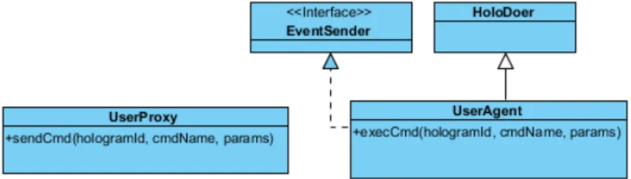
We call this entity an “user agent” as it is the virtual counterpart of the user, executing actions and commands on his behalf. This entity is strongly tight to the networking system, since it is the point where user sent commands and messages are interpreted and then eventually executed. This calls for a standardization of messages structure, ensuring that parameters sent over the network can be unserialized in some way.
3.5 User modeling and interaction 3. Envisioning the framework
Figure 3.5: Structural diagram of object regarding user modeling. UserAgent is the object that place the user inside the Augmented World. UserProxy is a simple entity that is used for remote interaction.
it could also have an Hologram associated representing the user itself.
The User Agent is then meant to be part of the server application; on the client side an User Proxy object is required in order to control the remote instance. This object is of course tight to the adopting networking system, and is from the client point of view the one gateway for user specific messages to the Augmented World.
3. Envisioning the framework 17 Figure 3.6: Example of in teraction in si de the framew ork. Notice that there’s no t guaran teed resp onse from the serv er, effec ts migh t b e seen from the clien t only if the action w as successfully executed on the Hologram. Other mec hanisms can b e placed b et w een the user agen t and serv er side holog rams to create a more complex p ermission based access system.
Chapter 4
The Unity Game Engine
Unity is a videogame engine well set in the industry, with an emphasis on portability, it allows development of 3d real time applications on top of different graphical libraries, including: Direct3D, OpenGL, OpenGL ES and other propri-etary APIs for video game consoles. Unity gives support to most commonly used 3D assets and formats, moreover it has an increasing sets of functionality like: texture compression, parallax mapping, SSAO, dynamic shadows, bump mapping, fullscreen post-processing effects, etc. The engine is targeting more and more plat-forms, and is also becoming one of the central technology onto which most known Augmented and Virtual reality tools are based upon.
4.1
Basics
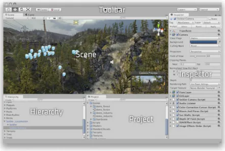
For building strong Unity-based applications, one must be first familiar with the provided Editor. The editor is a standalone program used not only to arrange objects into the scene, it is in fact an essential part of the developing process, providing useful functionality in the configuration of overall aspects of the program. Scripts order of execution, configuration of in-scene properties at start time, key-command binding, rendering properties, audio and image compression, are all features handled by this tool.
The main editor window is made up of several tabbed panels known in Unity as Views. There are several types of Views in Unity each one with a specific purpose.
The Project Window displays the library of assets that are available to use in the project. When you import assets into your project, they appear inside this view. This include prefabs (precomposed objects created directly from the scene), textures, materials, audios, meshes, etc.
4.1 Basics 4. The Unity Game Engine
Figure 4.1: The Unity Editor interface.
The Scene View allows you to visually navigate and edit your scene. This view has a 3D and 2D perspective, depending on the type of project you are working on. The Scene View can be used to select and position scenery, characters, cameras, lights, and all other types of Game Object.
The Hierarchy contains every GameObject in the current Scene. These objects can either be legacy Unity entities like basic shapes, lights, the camera, while other might be assets imported into the project. Objects can be arranged inside this view making use of Parenting; simply by dragging one object on top of another. As objects are added and removed from the scene, they will appear and disappear from the Hierarchy as well. By default the GameObjects will be listed in the Hierarchy window in the order they are made.
The Inspector Window shows all the properties of the currently selected ob-ject. These properties are public variables defined in the component script, and can be edited at both setup and run time. Because different types of objects have different sets of properties, the layout and contents of the inspector window will often vary.
The Toolbar provides access to the most essential working features. On the left it contains the basic tools for manipulating the scene view and the objects within it. In the center are the play, pause and step controls for running the application inside the editor.
4. The Unity Game Engine 21
4.2
Component based development
Unity is a component based engine, adopting a design pattern that was origi-nally pioneered in order to avoid annoying class hierarchies. The idea is to package all functionality of Game Objects into separate behaviour-based scripts. A sin-gle GameObject is just the sum of his parts, being them legacy or user written components.
Unity comes with a vast set of legacy components used to extend one Game Object’s functionality in terms of graphics, physics, user interface, audio, etc. User written scripts are mostly meant to be newborn components for GameObjects, following a well defined structure in concern of the engine execution lifecycle[10].
This reused-based approach to defining, implementing and composing loosely coupled independent components into systems is widely used in game engines and is one of the fundamental design pattern adopted to give the user the right flexibility to deal with most of the complexity brought by 3D real time applications[11].
GameObject components can be assigned inside the Inspector View, or by script, using the AddComponent call of GameObject. Each public property is directly rendered inside the Inspector with a special controller, to aid the developer in both configuration and debugging.
4.3
Runtime Engine Overview
Most of the complexity of Unity built games is hidden behind the inner runtime engine. This engine is the core of all Unity applications and even if his main structure is hidden from the public eye, we can still have a simplistic view at its possible implementation.
The Unity runtime is written in C/C++. Wrapped around the Unity core is a layer which allows for .NET access to core functionality. This layer is used by the user for scripting and for most of the editor UI.
This core is what really handles, in what is expected to be the most efficient way possible, the application main loop, including aspects regarding resource handling, front-end initialization and shoutdown, input decoupling and more.
At their heart, graphical real-time applications, such as videogames, are driven by a game loop[12] that performs a series of tasks every frame. By doing those tasks every frame, we put together the illusion of an animated, living world. The tasks that happen during the game loop perform all the actions necessary to have a fully interactive game, such as gathering player input, rendering, updating the world, and so forth. It is important to realize that all of these tasks need to run in one frame.
4.3 Runtime Engine Overview 4. The Unity Game Engine
4. The Unity Game Engine 23
main while block that sequentially calls all subsystem functionality to be executed in a single frame. This would also include the execution of all component-specific update functions for that exact frame rate. It’s clear that without a proper struc-ture and optimization the result would be quite unpleasant, even after adopting the fixed time step & variable rendering practice[13].
A more optimized solution can be earn by exploiting caching. The approach is to store all game objects inside a sequential array, so that calls to the components update function can be made following the memory linear traversal[14]. The idea here is that when you retrieve something from the RAM the likelyhood of requiring to fetch something nearby is high, so the data in that area is grabbed all at once. Of course this approach would have some impact on the complexity of game object deletetion, but it’s often unnoticeable.
Another solution would be exploiting parallelism, in one multiprocessor game loop architecture. A way to take advantage of parallel hardware architecture is to divide up the work that is done by the game engine into multiple small, relatively independent jobs. A job is best thought of as a pairing between a chunk of data and a bit of code that operates on that data. When a job is ready to be run, it is placed on a queue, to be picked up and worked on by the next available processing unit. This can help maximize processor utilization, while providing the main game loop with improved flexibility[15].
Structure 4.1 A naive approach for building a game object. Note that the code isn’t optimized to fully exploit caching.
c l a s s GameObject {
public :
Component ∗GetComponent ( i d ) ;
void AddComponent ( Component ∗comp ) ; bool HasComponent ( i d ) ;
private :
s t d : : v e c t o r <Component ∗> m components ; } ;
Structure 4.2 The naive approach for a system update would be to pass a list of game objects like so.
4.4 Vuforia support 4. The Unity Game Engine
void Engine : : Update ( f l o a t dt ) {
f o r ( u n s i g n e d i = 0 ; i < m systems . s i z e ( ) ; ++i )
m systems [ i ] . Update ( dt , O b j e c t F a c t o r y −>G e t O b j e c t L i s t ( ) ) ; }
4.4
Vuforia support
Vuforia is a software stack for building AR applications with a large set of carefully encapsulated advanced computer vision features. Vuforia’s recognition and tracking capabilities can be used on a variety of images and objects, like: single marker, multi-markers, cylinder targets, text and objects.
Vuforia provides tools for creating targets, managing target databases and securing application licenses. The Vuforia Object Scanner (available for Android) helps developers to easily scan 3D objects into a target format that is compatible with the Vuforia Engine. The Target Manager is a web app available on the developer portal that allows you to create databases of targets to use locally on the device, or in cloud. Developers building apps for optical see-through digital eyewear can make use of the Calibration Assistant which enables end-users to create personalized profiles that suit their unique facial geometry. The Vuforia Engine can then use this profile to ensure that content is rendered in the right position.
The Vuforia Extension for Unity comes as a simple unitypackage and allows developers to create AR applications and games easily using the Unity game engine. Installing the extension is just a matter of extracting the package inside the project and setup the provided prefabs into the scene. We’ll briefly explain the basic steps on how to setup a simple Unity project.
License Key The first thing to do before starting using Vuforia, is to obtain a license key for the application to be used inside the project. The license key can be easily created using the developers portal, after subscribing as a developer. Adding Targets In Vuforia, objects that can be identified by the computer vision system are called targets. For target binding, the extension provides a vast number of prefabs ready to be used inside the scene. Before starting using this components, however, we need to tell the scripts how these targets can be detected. We need to add a Device Database to our project, this can be done by
4. The Unity Game Engine 25
either creating a new database or using an existing one. To create a new database we need to use Vuforia Target Manager. After that, we just double-click on the downloaded package to import it into the project.
Figure 4.3: Assets imported into the project by Vuforia. ImageTarget, Object-Target, MultiTarget are all prefabs implementing a behaviour that automatically handles the recognition and binding of one target.
Add AR assets and prefabs to scene Now that we have imported the Vuforia AR Extension for Unity, we can easily adapt our project to use augmented reality. First of all we need to delete, or disable, the scene Main Camera, replacing it with ARCamera from the Prefabs folder instead. This object is responsible for rendering the camera image in the background and manipulating scene objects to react to tracking data. Remember that this object needs to be configured with a legit license key. The Database Load Behaviour script also needs the list of DataSets to be loaded when the application starts.
We now drag an instance of ImageTarget into the scene, the object that rep-resents the marker inside the scene. By looking at the Inspector we see that the object has an ImageTargetBehaviour attached, with a property named DataSet. This property contains a drop-down list of all available Data Sets for this project. When a Data Set is selected, the Image Target property drop-down is filled with a list of the targets available in that Data Set. We can now select the DataSet and Image Target from StreamigAssets/QCAR, these are the same target we’ve generated in the TargetManager.
Add 3D objects to scene and attach to trackables We can now bind 3D content to our Image Target, we just need to place it as a child object of our
4.5 The High Level API (HLAPI) 4. The Unity Game Engine
ImageTarget by dragging it on top of the parent inside the Hierarchy window. We can now test the application, the results should show the 3D content under the ImageTarget bound to the physical marker.
(a) An Image Target (b) Vuforia Target Manager
Figure 4.4: After an image with a good entropy is added to the dataset using the manager, it can be easily used as an image target.
More informations on how to setup the Vuforia extension for Unity can be found on the website in the developer’s library[16].
4.5
The High Level API (HLAPI)
There are tons of different ways for dealing with networking in Unity. For example one is free to choose between different legacy and currently holding net-working systems, like Unet, the Low Levl API and others, while still being able to handle .Net sockets directly. However the problem of portability persist, and while working with Unity it is advised to use always engine specific functions, since they are already part of the application lifecycle.
The High Level API (HLAPI)[17] is a the current standard for developing multiplayer games. It was introduced with Unity 4 promising to make the code regarding networking more maintainable, compared to the previous Unet system. It uses the lower transport layer for real-time communication, and handles many of the common tasks that are required for multiplayer games. While the transport layer supports any kind of network topology, the HLAPI is a server authoritative system; although it allows one of the participants to be a client and the server at the same time, so no dedicated server process is required.
The HLAPI allows developers to:
4. The Unity Game Engine 27
Figure 4.5: The Image shows the various layers of functionality of HLAPI, using as a base the Low Level API. Each layer is either a class, component or GameObject provided by Unity.
• Operate “client hosted” games, where the host is also a player client. • Serialize data using a general-purpose serializer.
• Send and receive network messages.
• Send networked commands from clients to servers.
• Make remote procedure calls (RPCs) from servers to clients. • Send networked events from servers to clients.
HLAPI uses functions that are embedded in the engine, it also provides ad-hoc editor extensions in order to ease the correct configuration of the scene. Part of the basic set of components and functionalities provided by the system are:
• A NetworkIdentity needed to give an unique reference to the object through the network.
• A NetworkBehaviour for writing networked scripts exposing: – An automatic synchronization mechanism for script variables. – Ways of performing remote procedures calls.
4.5 The High Level API (HLAPI) 4. The Unity Game Engine
– Message sending capabilities.
• A Configurable automatic synchronization of object transforms, provided by the NetworkTransform component.
• Support for placing networked objects into the Unity scenes.
Spawning entities In Unity, GameObject.Instantiate creates new Unity game objects. But with the networking system, objects must also be “spawned” to be active on the network. This can only be done on the server, and causes the ob-jects to be created on connected clients. Once obob-jects are spawned, the Spawning System uses distributed object life-cycle management and state-synchronization principles.
Players, Local Players and Authority In this networking system, player objects are special. There is a player object associated with each person playing the game, and commands are routed to that object. A person cannot invoke a command on another person’s player object, but only on their own. So there is a concept of “my” player object. So, in contrast of common single player games, the “local player” object must first be instantiated by the server, and then added into our scene locally.
State Synchronization State Synchronization is done from the Server to Remote Clients. Data is not synchronized from remote clients to the server, this is a job for Commands.
There are two different ways to stream data from server to clients, first is an automatic process through the concept of SyncVars, the other is by writing custom serialization and deserialization callbacks.
SyncVars are member variables of NetworkBehaviour scripts that are synchro-nized from the server to clients. When an object is spawned, or a new player joins a game in progress, they are sent the latest state of all SyncVars on networked objects that are visible to them. Member variables are made into SyncVars by using the [SyncVar] custom attribute.
SyncVars can be basic types such as integers, strings and floats. They can also be Unity types such as Vector3 and user-defined structs. SycnVar updates are sent automatically by the server when the value of the variable changes, so there is no need to perform any manual dirtying of fields for SyncVars.
Remote Actions SynchVars are a way to stream data from the server to his clients. HLAPI also offers a way to send specific message from client to server and vice versa . These type of actions are sometimes called Remote Procedure Calls.
4. The Unity Game Engine 29
There are two types of RPCs in the networking system: Commands, which are called from the client and run on the server and ClientRpc calls, which are called on the server and run on clients.
Figure 4.6: The diagram shows different types of interactions supported by HLAPI. Inside a NetworkBehaviour script the developer can use all provided attributes, as long the right conditions are met.
The arguments passed to commands and ClientRpc calls are serialized and sent over the network. These arguments can be:
• basic types (byte, int, float, string, UInt64, etc) • arrays of basic types
• structs containing allowable types
• built-in unity math types (Vector3, Quaternion, etc) • NetworkIdentity
• NetworkInstanceId • NetworkHash128
4.6 Editor extension 4. The Unity Game Engine
• GameObject with a NetworkIdentity component attached
Arguments to remote actions cannot be subcomponents of GameObjects, such as script instances or Transforms. They can’t be any other unserializable types.
4.6
Editor extension
Unity lets developers extend the editor with their own custom views and inspec-tors. It is possible, in fact, to create complex editor windows usable to automatize the creation and management of in-scene objects; or to use property drawers in order to define how properties are visualized for all instances of a particular script.
Property Drawers have two uses:
• Customize the GUI of every instance of a Serializable class. This can be done by attaching a new class that extends PropertyDrawer to a Serializable class by using the CustomPropertyDrawer attribute and pass in the type of the Serializable class that this drawer is for.
• Customize the GUI of script members with custom Property Attributes. This can be used to limit the range of values of a specific attribute of a component, or simply for changing how it is displayed inside the inspector. This can be done by writing a class placed inside the Editor that has the CustomPropertyDrawer attribute to which it’s specified the name of the attribute to render.
By extending the editor it is not only possible to shape how custom components are rendered and used by the developer in the Inspector, but we’re also able to write code that is directly executed inside the editor while defining the scene.
It is not hard to extend the editor main menu, adding new items and create custom windows. Making a custom Editor Window involves the following simple steps:
• Create a script that derives from EditorWindow. • Use code to trigger the window to display itself. • Implement the GUI code for drawing the content.
Scripts extending the editor needs to be placed under a subfolder of Assets named Editor. These scripts are then automatically executed during the editor lifecycle at the right moment, there’s no need to compile them by hand, everything is handled automatically by the editor’s runtime.
4. The Unity Game Engine 31
Example 4.3 Example of a custom window in C# using U ni t yE n gi n e ;
using U n i t y E d i t o r ;
using System . C o l l e c t i o n s ;
c l a s s MyWindow : EditorWindow {
//The a t t r i b u t e t e l l s t h e e d i t o r t o p l a c e // t h e window i n t h e t o p menu under t h e
// l o c a t i o n ”Window” w i t h t h e name ”My Window” [ MenuItem ( ”Window/My Window” ) ]
public s t a t i c void ShowWindow ( ) {
EditorWindow . GetWindow ( typeof (MyWindow ) ) ; }
void OnGUI ( ) {
// The a c t u a l window c o d e g o e s h e r e }
}
More information about how Unity editor can be extended can be found in the documentation[18].
Chapter 5
Development
In this chapter we’re discussing the development of the AW framework, speci-fying the implementation of concepts previously exposed in the design section.
The objective is not to write a software stack that implements all Augmented World functionality from the ground up, but instead to use different technologies to address most complex requirements by binding them together, in order to have a taste of simple AW framework for writing 3D Augmented World programs.
Choosing Unity as a 3D real-time engine we have the advantage of a tool that encapsulates most of the core functions required by Augmented World programs, providing ready to use means for developing graphics, geometry of the environment and handling real-time behaviours.
Following we’ll see how to exploit Unity advanced features to develop a frame-work on top of the engine that also extends the editor. We’ll discuss the imple-mentation of all basic AW framework concepts exposed in the previous chapters.
5.1
Hologram
Let’s take a look at the framework’s implementation of the Hologram concept. Since Unity is a component-based engine, it’s only natural for the Hologram to be in fact an extension of the MonoBehaviour class.
We present HologramComponent, the concrete implementation of an Hologram, shaped by the sum of his parts. Its usage is based on top of the basic aspect of the component pattern. The functionality of an Hologram is sparse between the three main concern exposed in the previous chapter; these objects, referred by the component, might as well not be present or not implementing a specific function for that Hologram, simply because there might be no need.
In this perspective, the View, Model and NetworkSynch parts of the Hologram all become Unity components as well, having the advantage to be all accessible
5.1 Hologram 5. Development
Figure 5.1: Class diagram of HologramComponent. Every module of Hologram is a Unity component as well.
from the same GameObject. The Hologram functionalities are shaped in a Unity-like fashion, the class isn’t meant to be extended, its behavior changes by the effect of his parts.
In practice we think that by separating the functionality of an Hologram into different components assigned to the same GameObject we have two main advan-tages.
The first one is that it’s possible to assign this entities trough the inspector and eventually handle its inspector-specific visualization trough an editor extension. This makes easier to the developer to track mistakes in the setup of the Hologram, in a more dynamic experience compared to the standard error message visualized in the debug console. Moreover it’s possible to have a major flexibility in writing specific behaviour-based scripts that can be parameterized from the editor.
The second advantage is that there’s no need for the developer to write struc-tural specific code. Everything is handled in a more dynamic way, since there’s no direct link between calls from an HologramCompoent to his parts.
5. Development 35
In this Unity-based framework, the Hologram becomes a well defined GameOb-ject to witch are assigned the View, Model and NetworkSynchronization compo-nents. Other legacy scrips might then be used to extend its functionality. For ex-ample, a mesh, collider and material component must be assigned to the GameOb-ject and then be properly handled by the View if we want it to be rendered on screen.
The HologramComponent is meant to be the main point of interaction with this specific Augmented Entity, its parts shouldn’t be accessed directly. When an HoloDoer, or some other entity, interacts with the Hologram, it is meant to be done directly through the Invoke method. This method propagates the call to the respective View, Model and NetSynch portions of the Hologram by checking out if the specified method is implemented on each subcomponent using reflection. This allows the developer to separate the payload of a method between the three main concerns, making the coding of an Hologram much cleaner and still quite flexible. Moreover this conceptual separation is critical if we want to build a framework that can work with different technologies, as said in the previous chapters.
An important aspect of an Hologram is that it is constantly rendered on top of the user perceived vision of the real world. This is intrinsically handled behind the scene by the chosen AR system. All HologramComponents are rendered applying the transformation matrix that is fetched directly by recognizing points of interest from the device video feed. The coordinates onto which the binding happens are specified by the world GameObject’s Transform, that is always used as a link from the virtual to the physical world. All HologramComponents should then be child of this GameObject, making their position relative to the physical point where space coupling happens.
Figure 5.2: The image shows an error in the configuration of this Hologram re-garding the HLAPI networking system.
Since this component might not be so much straight forward to use, and re-quires the copresence of his parts to work properly, an ad-hoc editor extension
5.1 Hologram 5. Development
comes to aid. The Inspector view of HologramComponent informs the developer about the correct configuration of that single augmented entity, in agreement to the currently holding framework specifics. For example, if Vuforia is the used AR technology, a message informing that the GameObject should have a parent with a TargetBehaviour is shown if that’s not the case.
5.1.1
View
The View Component is meant to handle all aspects of an Hologram regarding his graphics. There’s no strong requirement for this component, besides imple-menting the IView interface, that makes him recognizable by the HologramCom-ponent.
What this script should be used for is to write essential graphic handling logic. Here we can rightfully find access to specific legacy components like: materials, mesh, animations, and so on. It should expose methods that change the Hologram visualization in some way and can make use of the standard Update method to perform some time-based animation.
Here is a list of legacy components that makes sense to handle inside the a View component:
• Any Mesh Renderer • RigidBody
• Any Colldier • Particle Effects • Animation • Materials
If the user needs to interact with this Hologram in any way, this component can also be used to catch input from the device (like the screen gestures, key pressing, etc), directly from the Update method. However for a correct separation it is advised to use a different component entirely, we’ll argue about this in later chapters.
This component is of course tight to Unity graphics and it is not mean to be reusable outside the Engine.
5. Development 37
5.1.2
Model
In its most pure form, an Hologram has memory, meaning it holds a state. This state needs to be consistent, accessed and updated, like any standard plain old object.
We encapsulate this simple concern inside a specific component, called Model. The Model holds data regarding the state of an Hologram, exposing methods that alter its state.
This object holds all structural information about an Hologram. Its instance has sense to be located only on the server process, since Hologram specific infor-mations are private and centralized. This doesn’t mean that redundancy can’t be used to exploit this component for handling synchronization errors on clients, improving fault tolerance in regard to faulty networks.
This script needs to extend MonoBehaviour and implement IModel, however this is only necessary because we want the object to be treated like an Unity component, so that it can appear inside the Inspector. A Model component is meant to be used like a standard OOP object, MonoBehaviour functions, especially Update, need to be ignored. This way, by removing MonoBehaviour from the class declaration, the object can also be used in other environments not bound to the Unity engine.
In brief, this object is used by this framework as a server-side data space for a specific Hologram. The Model isn’t accessed directly form other scripts, his state is regulated by calls performed by its HologramComponent.
5.1.3
Network Synchronization
One major concern about Holograms regard their synchronization mechanism. In our envisioned network architecture, one central node holds the main instance of the world, from which others update their view state.
This main instance is what really has the authority on all Hologram related data and functions. Clients can request for a specific action be executed on a Hologram by sending particular interaction messages, that we call commands. Client-side Holograms are continuously notified about updates to their remote counterpart, so that they can quickly react and update their visualization accordingly.
The behaviour surrounding message passing and data transfer between clients and server is encapsulated in a framework specific component. This component is the Network Synchronization one.
The Network Synchronization component is tight to the specific type of Net-working System chosen for the application, whose functions are provided by some sort of Network Manager. This means that in the future, if the provided Network-ing System doesn’t sweets the developer needs, it can be swapped out by only
5.1 Hologram 5. Development
5. Development 39 Figure 5.3: Bird’ s-ey e view of cl ien t-serv er in teraction in the framew ork. The figure sho ws the tw o main functions of the Net w ork Sync hronization comp onen t. The first o ne is the streaming of comp onen t sp ecific data from the serv er to all cli en ts b y mean s of a Sync hV ar. The second one is the round trip of a command, that starts fro m a sp ecific clien t instance and is ev en tuall y propagated to others b y the serv er if it’s necessary .
5.1 Hologram 5. Development
Currently the AW Framework only supports the Unity based High Level API for Networking. We choose to start from this Networking System because it’s embedded in latest versions of Unity and already addresses most of the networking problems related to real-time distributed applications.
Being HLAPI on top of the real-time communication layer, it provides some standards that needs to be followed in writing the remote communication code. The following actions needs to be taken care of before writing the Network Syn-chronization component using HLAPI:
• Assign a Network Identity to the Hologram.
• Ensure that this GameObject is saved into a prefab so it can be instantiated at runtime.
• Create a component extending HLAPINetworkSynch abstract class.
HLAPINetworkSynch is the base class implementing functions that make use of the AWNetworkManager. It requires the import of the UnityEngine.Networking library, since it derives from the engine’s NetworkBehaviour class. NetworkBe-haviours are special scripts that work with objects having a NetworkIdentity com-ponent, these scripts are able to perform HLAPI functions such as Commands, ClientRPCs, SyncEvents and SyncVars.
Using HLAPI can make the process of writing the code for view-model syn-chronization quite easy, since the coordination mechanism for that Hologram is all limited to the same component. This means that both server and client side of the code are placed inside the same script. This is the standard when dealing with NetworkBehaviours.
Inside a script that derives from HLAPINetworkSynch we can make use of different synchronization mechanisms. Being this an extension of a NetworkBe-haviour we can use SynchVar to dynamically update the state of a variable from server to clients. We can also make use of standard message passing, on top of which it is build the SendCmd function, used to remotely invoke methods on the specific server-side Hologram. Moreover, the attribute [ClientRPC] can be used in order to remotely invoke a method from server to all clients.
HLAPINetworkSych registers itself for remote messages from AWNetworkMan-ager automatically as soon as a remote connection is established.
The method SendCmd() is used to remotely invoke a method on the same Hologram. The arguments of the call are automatically serialized in a stream of bytes, but they require to be basic types, implement Serializable or be built-it Unity math types (like Vector3, Quaternion, etc).
It is possible to use the method AskCurrentStateMessage() to receive specific information on the remote state of that Hologram. For this mechanism to work,
5. Development 41
Figure 5.4: The figure shows the process behind the SendCmd call. The message is sent through the network as a bytestream by the AWNetworkManager. The message can’t reach the Hologram directly, it has to pass trough PlayerAgent, of witch the client has the authority.
the developer must implement the abstract methods GetCurrentState and OnCur-rentStateReceived.
GetCurrentState() is meant to generate a message holding a snapshot about the Hologram state of affairs. It returns a StateMessage that holds data with a key-value specification. OnCurrentStateReceived is the handler of the message, so it is meant to fetch data from the StateMessage and update the Hologram’s view accordingly.
This mechanism is useful when a client connects to the server and needs to fetch all meaningful Hologram information at once. By doing this, its view can be updated with the remote Hologram’s data, and the synchronization process can continue from that point forward. AskCurrentStateMessage() isn’t meant to be used repeatedly, for a continuous update of the Hologram’s representation it’s advised for SynchVars to be used instead.
5.1 Hologram 5. Development Figure 5.5: In teraction diagram fo r the AskCur ren tStateMessage() call. Messages are serialized and unserialized in to ob jects on b oth parts.
5. Development 43
5.2
User shape and interaction
The User needs to be part of the model of the world. There are various reasons for this, already addressed in the previous chapters. First of all, autonomous entities might reason about the position and state of users. Secondly we need a client specific means of interaction, especially if we want to use HLAPI.
When a clients joins the scene, a special GameObject is instantiated at runtime by the AW Framework Manager. This GameObject is bound to a specific client instance, that owns the authority for that object. This means that the application can send Commands to that particular entity alone. By using Commands we can trigger server side execution of code for scripts deriving from Network Behaviour of which the client owns the authority.
For security reasons the User Agent is the only one GameObject a client can own the authority. The structure of this entity needs to be known by the AW Network Manager, so that it can be automatically instantiated and destroyed at runtime.
The framework already provides a standard GameObject inside the assets folder to be used for development and testing. This prefab is really basic, it only holds the required PlayerCommands script without any other specific component, besides the Network Identity one.
PlayerCommands expose the method Interact that can be used to remotely invoke a method of the specified Hologram, enabling remote interaction. This method doesn’t directly use the attribute [Command], but instead it simulates its behaviour trough the use of an Interaction Message. This was necessary in order to enable the developer to extend the set of supported data types that can be used as an argument.
Example 5.1 PlayerCommands script - exposing the Interaction method. // / <summary> // / I n t e r a c t w i t h t h e p a s s e d o b j e c t c a l l i n g // // t h e s p e c i f i e d method name . // / </summary> // / <param name=”go”>GameObject r e f e r e n c e // / w i t h N e t w o r k I d e n t i t y .</param>
// / <param name=”method”>Method name.</param>
// / <param name=” a r g s ”> S e r i a l i z a b l e p a r a m e t e r s </param> public void I n t e r a c t ( GameObject go , s t r i n g method ,
5.2 User shape and interaction 5. Development i f ( i s C l i e n t ) { netManager . S e n d I n t e r a c t i o n M e s s a g e ( go , method , a r g s ) ; } e l s e i f ( i s S e r v e r ) { O n G a m e O b j e c t I n t e r a c t i o n ( go , method , a r g s ) ; } } [ Command ]
void CmdInteract ( GameObject go , s t r i n g method ) { HologramComponent hc = go . GetComponent<HologramComponent> ( ) ; i f ( hc != n u l l ) { hc . I n v o k e ( method ) ; } e l s e { Debug . LogWarning ( ”Can ’ t f i n d HologramComponent f o r ” + go . name + ” u s i n g SendMessage i n s e t e a d ” ) ; go . SendMessage ( method ) ; } }
public s t a t i c void O n G a m e O b j e c t I n t e r a c t i o n ( GameObject go , s t r i n g method , object [ ] a r g s ) { HologramComponent hc = go . GetComponent<HologramComponent> ( ) ; i f ( hc != n u l l ) { hc . I n v o k e ( method , a r g s ) ; } e l s e { i f ( a r g s != n u l l && a r g s . Length > 0 ) { go . SendMessage ( method , a r g s [ 0 ] ) ; } e l s e { go . SendMessage ( method ) ; } } }