Ing. Mohammad Muhshin Aziz Khan
LASER BEAM WELDING OF
STAINLESS STEELS
UNIVERSITÀ DI PISA
Scuola di Dottorato in Ingegneria “Leonardo da Vinci”
Corso di Dottorato di Ricerca in
INGEGNERIA MECCANICA
Tesi di Dottorato di Ricerca
Università di Pisa
Corso di Dottorato di Ricerca in
Ingegneria Meccanica
Laser Beam Welding of Stainless Steels
Tesi svolta per il conseguimento del titolo di dottore di ricerca
Settore Scientifico Disciplinare: ING-IND/16 .
Allievo:
Ing. Mohammad Muhshin Aziz Khan
Relatori:
Prof. Gino Dini (DIMNP, Pisa)
Prof. Marco Beghini (DIMNP, Pisa)
Ing. Marco Fiaschi (Continental Automotive
Italy SpA)
X Ciclo Anno 2012
Allievo:
Mohammad Muhshin Aziz Khan ___________________
Relatori:
Prof. Gino Dini ________________________ Prof. Marco Beghini ________________________ Ing. Marco Fiaschi ________________________
Laser Beam Welding of Stainless Steels
Anno 2012
UNIVERSITÀ DI PISA
Scuola di Dottorato in Ingegneria “Leonardo da Vinci”
Corso di Dottorato di Ricerca in
Ingegneria Meccanica
Tesi di Dottorato di Ricerca
ABSTRACT
The main objective of this research is to study the laser beam welding of stainless steels. During experimentation, a 1.1kW CW Nd:YAG laser is used to weld as-received similar martensitic and dissimilar austenitic/ferritic stainless steels in overlap and fillet joint configurations respectively. The influence of various operating parameters such as laser power, welding speed, fiber diameter, angle of incidence, and the defocus distance, and their interactions on the weld bead geometry and mechanical properties are examined. Effects of energy density and line energy, two key process parameters from energy perspective, on the weld bead characteristics are also investigated to understand certain energy dependent welding phenomena, and to show their consequent impact on the aforesaid factors. Moreover, formation of solidification microstructures and the distribution pattern of the segregated alloying elements in the weld with varied energy input are studied and correlated with the corresponding change in local microhardness.
In order to predict and optimize the laser welding of these economically important and technologically critical stainless steels in automotive industry, full factorial design (FFD) and response surface methodology (RSM) are respectively used as a design of experiment (DOE) approach to design the experiments, develop the mathematical models, and optimize the welding operation. In these studies, for each welded material, mathematical models are developed to predict the required responses. Furthermore, the developed models are optimized by determining the best combinations of input process parameters to produce an excellent weld quality.
Finally, considering the experiment-based evidences i.e. weld resistance length is energy-limited and weld penetration depth is the characteristic factor determining the resistance length, a simplified energy-based model is developed for laser welding of ferritic stainless steels in overlap joint configuration. The developed model is quite accurate in predicting the weld penetration depth directly from the welding input parameters provided that welding is conduction-limited.
SOMMARIO
Obiettivo principale di questa tesi di dottorato è quello di studiare la saldatura laser degli acciai inossidabili. Durante gli esperimenti un laser Nd-YAG in onda continua da 1.1kW è stato utilizzato per saldare rispettivamente acciai martensitici in configurazione di piena penetrazione e combinazioni di acciai austenitici/ferritici in configurazione d’angolo. È stata studiata l’influenza di vari parametri di processo come potenza del laser, velocità di saldatura, diametro della fibra, angolo di incidenza e defocalizzazione nonché le loro interazioni sulla geometria del giunto e sulle sue proprietà meccaniche. Si sono analizzati, inoltre, gli effetti della densità di energia e dell’energia per unità di lunghezza sulle caratteristiche del giunto di saldatura in modo da evidenziare la dipendenza del processo dai fenomeni di scambio termico. Successivamente si è studiato la microstruttura della solidificazione del giunto e la relativa distribuzione degli elementi di lega per diversi valori della densità di energia correlandole con la variazione locale della microdurezza.
Durante il corso della ricerca, sono state utiliizzate tecniche di DOE come il FFD ed il RSM con l’obiettivo di modellare ed ottimizzare il processo di saldatura laser. In questa fase, per ogni materiale saldato sono stati elaborati dei modelli in grado di determinare i fattori chiave che governano il processo. Tali modelli, inoltre, sono stati ottimizzati prendendo in considerazione la combinazione dei parametri di processo che consente di avere giunti di qualità superiore in termin di geometria e caratteristiche meccaniche.
È stato, infine, elaborato un modello teorico per la determinazione della geometria di un giunto ottenibile dalla saldatura in piena penetrazione di acciai ferritici. Tale modello si basa sul concetto che la geometria risultante è funzione del tipo di scambio termico che si genera durante il processo e che a sua volta tale scmbio termico vari in funzione della densità di energia fornita dla laser. Il modello ha dimostrato una corrispondenza con i dati sperimentali con una maggior accuratezza nel caso di saldatura per conduzione.
ACKNOWLEDGMENTS
I was fortunate to have Professor Gino Dini as my main supervisor, and Professor Marco Beghini together with Ing. Marco Fiaschi as my co-supervisors. I would like to express my gratitude and appreciation for their constant guidance, valuable suggestions and encouragement during the completion of this research.
Special thanks to Dr. Luca Romoli, Department of Mechanical, Nuclear and Production Engineering, University of Pisa, for his constant support, friendly enthusiasm, constructive criticism, and motivation, which were the real driving forces behind this work. Without the discussions which I had with him, it would not have been possible for me to give a positive shape to this work. I am also thankful to his wife, Ilaria Fiori and the little master, Giulio Romoli, who made me to feel like ‘I-am-at-home’ every time I visited them.
I am grateful to Continental Automotive Italy SpA for having offered the scholarship for pursuing the doctoral study at University of Pisa. They also provided the equipment in the form of their Nd:YAG laser and on site analytical equipments. Thanks are due to Ing. Carmela Fierro for her sound technical support during the work conducted at Continental Automotive.
Special thanks go to Professor Marco De Sanctis and Randa Ishak from Department of Chemical Engineering, Industrial Chemistry and Materials Science at University of Pisa for their assistance in microstructure characterization and microhardness profiling.
I am tempted to individually thank all of my friends who, from my childhood until now, have joined me in the discovery of what is life about and how to make the best of it. However, because the list might be too long and by fear of leaving someone out, I will simply thank you very much to you all. Anyways, some of you quite lucky are: Zaki, Jamil, Lincon, Habib, Afzal, Leen, Wahab, Zahir, Mithu, Sayem, Nasima, Vivi, Salvatore I & II, Flavio, V. Romoli, Anis, Ranjan, Sakib, Himel, Mahamood, Malek, Shamsuzzoha, Arif, Mukaddes, Rashed, Gabriele, Gualtiero, and Vinicio for being some of my very best friends.
My deepest gratitude goes to my mother, Farida Akter Khanam, for her unconditional love, care, advice, and encouragement throughout my entire life. Although my father, Abdul Qaiyum Khan, is no longer with us, he is always there with me. If he were alive, he would be very proud of me and my work. My special gratitude is to my brothers and sisters who have given me an unflagging love and support throughout my life. Special thanks to my father-in-law, Faruque Ahmed, mother-in-law, Anwara Khatun, and two sisters-in-law for their love and support. And last but not least, I am sincerely indebted to my beautiful wife, Nahida Zafrin Tuly and our lovely son, Nazeef Nuwaisir Khan, who are indeed very special part of my life. This thesis would not have been possible without their incredible amount of love, care, encouragement, and patience throughout the years. I love you much more than I can express.
INDEX
ABSTRACT iii
ACKNOWLEDGMENTS v
1. INTRODUCTION 1
1.1 PREFACE 2
1.2 LASER BEAM WELDING 2
1.2.1 Laser material interaction 4
1.2.1.1 Conduction mode welding 4 1.2.1.2 Keyhole mode welding 5
1.2.2 Selection of laser welding 6
12.3 Selection of Nd:YAG laser as a heat source 7 1.2.3.1 Shielding gases for Nd:YAG laser welding 8
1.3 SELECTION OF STAINLESS STEEL 8
1.3.1 Metallurgical aspects of laser welding 9
1.4 QUALITY ISSUES FOR LASER WELDING 10
1.4.1 Weld bead geometry 10
1.4.2 Weld defects 10
1.4.3 Factors affecting the weld quality 12
1.4.4 Welding process optimization 13
1.5 ANALYTICAL MODEL DEVELOPMENT 14
1.6 RESEARCH MOTIVATION 15
1.7 OBJECTIVES OF THE PRESENT RESEARCH 15
1.8 THESIS STRUCTURE 17
REFERENCES 18
2. LASER BEAM WELDING OF MARTENSITIC STAINLESS STEELS IN AN OVERLAP JOINT CONFIGURATION
21
2.1 INTRODUCTION 22
2.1.1 Research objectives 24
2.2 MATERIALS AND EXPERIMENTAL PROCEDURES 24
2.2.1 Materials 24
2.2.2 Laser welding experimental procedures 25
2.3 RESULTS AND DISCUSSION 28
2.3.1 Effects on weld bead characteristics 28 2.3.1.1 Weld profile aspects 28
2.3.1.2 Weld width 29
2.3.1.3 Weld penetration depth 30 2.3.1.4 Weld resistance length 32
2.3.2 Effects on mechanical properties 34
2.3.2.1 Weld shearing force 34
2.3.2.2 Shrinkage 36
2.3.3 Selection of allowable range of energy density input 36
2.4 CONCLUSION 37
REFERENCES 38
3. EXPERIMENTAL STUDY ON MICROSTRUCTURE
EVOLUTION IN LASER WELDED MARTENSITIC STAINLESS STEELS
41
3.1 INTRODUCTION 42
3.1.1 Research objectives 43
3.2 EXPERIMENTAL 44
3.3 RESULTS AND DISCUSSION 45
3.3.1 Weld microstructures and microhardness profiles 45
3.3.1.1 Fusion zone 46
3.3.1.2 Heat-affected zone 51
3.4 CONCLUSION 53
REFERENCES 53
4. EXPERIMENTAL DESIGN APPROACH TO LASER WELDING
PROCESS OPTIMIZATION FOR OVERLAP
CONFIGURATION
55
4.1 INTRODUCTION 56
4.11 Research objectives 58
4.2 MATERIALS AND METHODS 59
4.2.1 Materials 59
4.2.2 Experimental design 60
4.2.3 Experimental work 61
4.2.4 Mechanical characterization 61
4.3 RESULTS AND DISCUSSION 63
4.3.1 Development of mathematical models 63 4.3.1.1 Response model selection 63 4.3.1.2 Analysis of variance (ANOVA) 65 4.3.1.3 Validation of developed models 69
4.3.2 Process parameter optimization 72
4.3.2.1 Numerical optimization 72 4.3.2.2 Graphical optimization 74
4.4 CONCLUSIONS 75
REFERENCES 75
5. LASER BEAM WELDING OF DISSIMILAR STAINLESS STEELS IN A FILLET JOINT CONFIGURATION
77
5.1 INTRODUCTION 78
5.1.1 Research objectives 79
5.2 MATERIALS AND EXPERIMENTAL PROCEDURES 80
5.2.1 Materials 80
5.2.2 Laser welding experimental procedures 81
5.2.3 Weld bead characterization 84
5.3 RESULTS AND DISCUSSION 84
5.3.1 Effects of process parameters 85
5.3.1.1 Weld bead geometry 85 5.3.1.2 Weld shearing force 87
5.3.2 Effects of line energy 88
5.3.2.1 Weld bead geometry 88 5.3.2.2 Weld shearing force 91
5.3.3 Angular distortion 92
5.3.4 Weld microstructures 93
5.3.5 Weld microhardness profile 95
5.4 CONCLUSIONS 96
REFERENCES 96
6. USING RESPONSE SURFACE METHOD TO LASER
WELDING PROCESS OPTIMIZATION FOR FILLET
CONFIGURATION
99
6.1.1 Research objectives 101
6.2 MATERIALS AND METHODS 101
6.2.1 Materials 101
6.2.2 Response surface methodology 102
6.2.3 Experimental design 103
6.2.4 Experimental work 105
6.2.5 Mechanical characterization 105
6.2.6 Optimization procedure 106
6.3 RESULTS AND DISCUSSION 107
6.3.1 Development of mathematical models 107 6.3.1.1 Response model selection 108 6.3.1.2 Analysis of variance (ANOVA) 109 6.3.1.3 Validation of models developed 114
6.3.2 Process parameter optimization 117
6.3.2.1 Numerical optimization 117 6.3.2.2 Graphical optimization 119
6.4 CONCLUSIONS 120
REFERENCES 120
7. A SIMPLIFIED ENERGY-BASED MODEL FOR LASER WELDING OF FERRITIC STAINLESS STEELS
123
7.1 INTRODUCTION 124
7.1.1 Research objectives 124
7.2 PENETRATION DEPTH MODELING 124
7.3 EXPERIMENTAL 127
7.4 RESULTS AND DISCUSSION 127
7.5 CONCLUSIONS 131
REFERENCES 131
8 GENERAL CONCLUSIONS AND SCOPE FOR FUTURE WORK
NOMENCLATURE
P Laser power [W]
S or v Welding speed [m/min]
F Optical fiber diameter [µm]
Φspot Focal spot diamter [µm]
A Angle of incidence [deg]
D Defocus distance [mm]
ED Energy density [J/mm2]
EDth Threshold energy density [J/mm
2
]
LE Line energy [kJ/m]
W Weld width [mm]
Dp Weld penetration depth [mm]
SL Weld resistance length [mm]
Pr Weld radial penetration [mm]
Fs Weld shearing force [N]
m Mass of the welded material [kg]
Qab Absorbed energy [J]
Qth Threshold energy [J]
K Reciprocal of specific energy [kg/J]
Tamb Ambient temperature [K]
Tm Melting temperature [K]
Tmax Maximum temperature [K]
Cps Specific heat in solid state [J/kg.K] Hm Latent heat at melting point [J/kg] Cpl Specific heat at liquid state [J/kg.K] PA Fraction of absorbed power [W] Ac Absorption coefficient
Pin Incident laser power [W]
Δt Irradiation time [min]
CHAPTER 1
INTRODUCTION
1.1 PREFACE
Welding is a process of joining the surfaces of two work-pieces (usually metals) through localized coalescence. It is a precise, reliable, cost-effective, and high-tech method for joining materials. No other technique is as widely used by manufacturers to join metals and alloys efficiently and to add value to their products. Most of the familiar objects in modern society, from buildings and bridges, to vehicles, computers, and medical devices, could not be produced without the use of welding.
Nowadays, welding goes well beyond the bounds of its simple description. This technique is applied to a wide variety of materials and products, using advanced technologies, such as lasers and plasma arcs. The future of welding holds even greater promise as methods are devised for joining dissimilar and non-metallic materials, and for creating products of innovative shapes and designs.
This chapter tries to clarify the various background issues concerning the laser beam welding of stainless steels.
1.2 LASER BEAM WELDING
Laser welding is a fusion joining process that produces coalescence of materials with the heat obtained from a concentrated beam of coherent, monochromatic light impinging on the joint to be welded and hence, belongs to the group of liquid-phase joining. The necessary energy is obtained from a focused laser beam which locally creates a melt pool that is moved along a joint resulting in a weld seam. These laser weld seams are typically narrower than can be produced by conventional welding techniques. The capability of laser welding to produce precise, repeatable joints at high process speeds offers a unique alternative to TIG welding, electron beam welding (EBW) and resistance welding.
The focused laser beam is one of the highest power density sources available to industry today. It is similar in power density to an electron beam as shown in the Fig. 1.1. Together these two processes represent part of the new technology of high energy density processing. However, vacuum and x-ray shielding are not required in LBW as laser can travel through air or vacuum with minimal loss of energy. These technological aspects provide competitive advantages to LBW over the EB welding from operation and cost standpoints. Moreover, unlike EBW, a wide range of dissimilar materials can be laser welded.
Fig. 1.1: Relative power densities of different heat sources [1] Air/Fuel Gas Flame Oxyacetylene Thermit Friction Arc Welding Resistance Welding (Oxygen Cutting) Electron Beam, Laser Beam 102 103 104 105 106 107 Power Density, W/cm2
Because laser welding is a high-energy density process, the material exposed to a sharply focused laser beam can melt or even vaporize to form a deep keyhole instantaneously, and welding is completed before much heat is conducted away into the bulk of the workpiece. The laser welding, therefore, results in better weld quality, deeper penetration depth, and less damage or distortion to the welded part as indicated in Fig. 1.2. Moreover, this low heat input to the welded joint has beneficial metallurgical consequences.
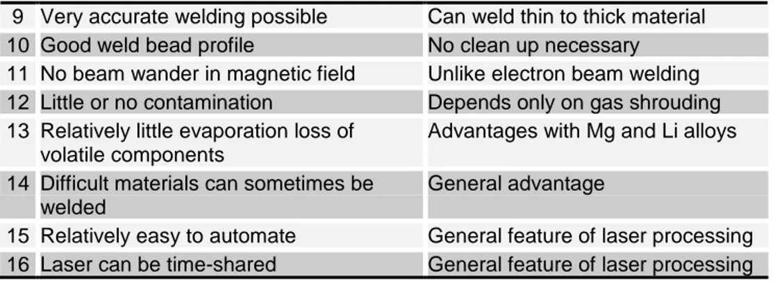
Fig. 1.2: Variation in heat input with the power density of heat source [2] The main characteristics of the laser beam welding are listed in Table 1.1. From the aforesaid table, it can be seen that the laser has something special to offer as a high-speed, high-quality welding tool. It also has advantages in areas requiring the welding of heat-sensitive components such as heart pacemakers, pistons assembled with washers in place, valve seat rest on a thin lower screen, and thin diaphragms on larger frames.
Table 1.1: Main characteristics of the laser beam welding [3]
Characteristics Comments
1 High energy density Less distortion
2 High processing speed Cost-effective (if fully employed) 3 Rapid start/stop Unlike arc processes
4 Welds at atmospheric pressure Unlike electron beam welding 5 No X-rays generated Unlike electron beam welding 6 No filler required (Autogenous weld) No flux cleaning
7 Narrow weld Less distortion
8 Relatively little HAZ Can weld near heat-sensitive materials Arc welding Gas welding High-energy beam welding Increasing: Penetration, Welding speed, Weld quality, Equipment cost Increasing: Damage to workpiece
Power density of heat sources
H e a t in p u t to w o rkp ie c e
9 Very accurate welding possible Can weld thin to thick material 10 Good weld bead profile No clean up necessary 11 No beam wander in magnetic field Unlike electron beam welding 12 Little or no contamination Depends only on gas shrouding 13 Relatively little evaporation loss of
volatile components
Advantages with Mg and Li alloys 14 Difficult materials can sometimes be
welded
General advantage
15 Relatively easy to automate General feature of laser processing 16 Laser can be time-shared General feature of laser processing
1.2.1 Laser material interaction
An important mechanism in laser beam welding is the interaction of the laser beam with the material. This interaction mechanism is influenced by many parameters, such as the laser power, the intensity distribution of this power at the surface, the welding speed, the material properties, the protection gas supply and the wavelength of the laser radiation. The latter is constant in this thesis, since only a Nd:YAG (λ =1.06 µm) laser is considered. As illustrated in the Fig. 1.3 (a)-(b), there are two modes of welding with the laser: conduction welding and keyhole or deep penetration welding. Each mode is characterized by different laser material interaction phenomena [4-5].
Fig. 1.3: Modes of welding with laser: (a) conduction and (b) keyhole welding
1.2.1.1 Conduction mode welding
This type of welding occurs at relatively low laser beam intensity (I < 1010 W/m2). The laser energy is absorbed by Fresnel absorption at the surface of the workpiece and can be described by an absorption coefficient A, indicating the fraction of absorbed laser power PA = A · P. For steel at the melting temperature (Tm = 1800
Laser beam Melt vapor Welding direction Melt pool Weld seam Vapor and plasma channel Laser induced plasma Laser beam Welding direction Melt pool Weld seam (a) (b)
K) the absorption coefficient is of the order of A = 0.4 for Nd:YAG laser radiation. The rest of the laser energy is reflected. For metal the laser energy is absorbed in a thin layer (~ 40 nm) at the surface of the workpiece where it is converted into heat. The absorbed energy is transported into the depths of the material solely through heat conduction, and the size of the weld pool is limited by the conduction of the heat away from the point that the beam impinges on the workpiece surface as shown in 1.4. For this reason, the weld depth ranges from only a few tenths of a millimeter to 1 millimeter. The heat conductivity of the material limits the maximum weld depth. If the heat is not able to dissipate quickly enough, the processing temperature rises above the vaporization temperature. Metal vapor forms, the welding depth increases sharply, and the process turn into deep penetration welding. In conduction welding, the laser produces a smooth, rounded seam that does not require any extra grinding or finishing. Pulsed or continuous-wave solid-state lasers are employed in such application.
Fig 1.4: Energy coupling into the material through (a) isotropic and (b) preferential z conduction depending on energy density input.
Fig. 1.5: (a) Energy coupling into the material, and (b) keyhole shape and energy absorption during keyhole welding [6].
1.2.1.2 Keyhole mode welding
As the intensity of the laser beam is increased (I ≥ 1010 W/m2), the molten metal in the focus of the laser beam starts to evaporate. The recoil pressure of the vapor pushes the melt aside, creating a capillary filled with hot metal gas or plasma. This capillary is known as the keyhole and can extend over the complete depth of the workpiece. The hot gas escaping from the keyhole forms plasma or plume above the workpiece as can be seen in Fig. 1.3(b). The laser beam energy is absorbed on the walls of the keyhole. The laser beam is exposed to the keyhole wall repeatedly due to the reflections down the keyhole as shown in Fig. 1.5 (b). At every reflection a fraction of the laser energy is absorbed. Because of this multiple reflections
(a) (b)
Molten pool Laser beam
Metallic vapor jet Keyhole Thin layer of liquid metal Solid Localized evaporation Hump
Recoil force induced Metal flow
(a) (b)
Welding direction
mechanism, keyhole mode welding has a high total absorption (> 80%). Furthermore, the gas inside and above the keyhole absorbs laser radiation by inverse Bremsstrahlung. For Nd:YAG laser radiation this absorption mechanism is very weak compared with the Fresnel absorption at the keyhole walls [7-8]. Due to the keyhole the energy is absorbed throughout the whole depth of the workpiece. This allows for high welding speeds in keyhole or deep penetration welding and results in welds with a high depth to width ratio and a small heat affected zone (HAZ).
1.2.2 Selection of laser welding
Laser welding, nowadays, is increasingly being used in industrial production ranging from microelectronics to shipbuilding. Automotive manufacturing, however, is among the industrial sectors which have proven to be most outstanding at developing applications that take advantage of the many benefits of this technology [9]:
- Low heat input;
- Small heat affected zone (HAZ); - Low distortion rate; and
- High welding speed.
These characteristics have made laser welding the process of choice for many applications that used conventional welding in the past. By adding the benefits of single-sided access, laser welding is given another strategic advantage, allowing it to open the door for a multitude of new applications.
Modern CNC multi-axis laser welding workstations can provide precise and repeatable welding. A successful laser weld, however, requires a combination of appropriate weld joint design, motion control, fixture design, metallurgy, production control, and quality systems.
All three of the most common joint configurations can be used: lap, butt, or fillet, but intimate contact between the materials at the joint is preferred. Under these conditions, high quality, low porosity, and controlled grain size welds with consistent weld depth and width can be achieved [10].
Weldable materials range from normal and high-strength constructional steels through to high-alloyed stainless steels. Titanium, aluminum, and nickel base materials can also be problem-free welded. Besides, high heating and cooling rates produce fine microstructures, which improve mechanical properties of the weld. Since the heat source is the energy of light, the workpiece is welded purely resulting in excellent fatigue strength of the welded joint as well.
The laser welds can be cost competitive based on minimum set-up time, low fixturing costs, high feed rates, and high-energy efficiency. Resultant welds generally have minimum part distortion with reduced rectification and decreased post-weld costs.
1.2.3 Selection of Nd:YAG laser as heat source
About 11 percent of industrial solid-state and CO2 lasers are integrated into
welding systems that are used in industries ranging from the manufacture of dental/surgical instruments on a micro scale to the macro scale, on-line assembly of automotive body-in-white. In between are a wide variety of industries, all with unique joining requirement, that make up general field of laser welding. And this diverse market, heavily product and metallurgy oriented, is one reason that laser welding has historically made up only 10-15 percent of the total laser market. Nowadays, the multi-kilowatt laser application and processing market is dominated by CO2 and Nd:YAG lasers, which combine to a total of more than 90% of all
installed laser systems. Since the late 1980’s when more than 80% of all installed multi-kilowatt lasers were CO2 lasers. The Nd:YAG lasers have constantly grown
their market share, which is now more than 50% [11]. Today with both systems being equally reliable, the focus shifts to the end user to pick the right system to address all of their customer requirements in respect to part quality and manufacturing cost. Recent breakthroughs in the field of laser diodes and fiber lasers present new opportunities for solving manufacturing tasks. However, these require thorough application-focused investigations in order to convert them into reliable manufacturing processes.
The main differences between Nd:YAG and CO2 laser sources are beam quality,
brightness, and wavelength [12]. Beam quality refers to the focusabiltiy of the laser, and brightness refers to the power density contained within the focused beam. Because the Nd:YAG laser is 1/10th the wavelength of the CO2 laser, it can be
focused to a spot size that is ten times smaller, and hence, the Nd:YAG laser has higher beam quality and brightness.
In laser welding, deep penetration and high speeds are directly related to high beam quality and brightness. However, weldability and tolerance accommodation tend to favor lesser beam quality and brightness. A balance, therefore, needs to be found between the welding performance and the quality of weld and size of the process window. It should be noted that there is always room to reduce the quality of the beam to match the application, but it is not possible to make a poor quality beam better.
This difference in wavelengths has also process and integration implications. The main process effect is that CO2 laser creates a stronger welding plume above the
weld, which diffuses the beam power density, reducing penetration and enlarging the weld width at the surface. However, during high-power Nd:YAG laser welding, the effect of plasma formation is only of secondary importance [12]. This is due to the shorter wavelength of Nd:YAG laser radiation, which is absorbed less in the plasma cloud compared to CO2 laser radiation, and the lower beam intensity.
Regarding integration, at 10.6 µm, the CO2 laser must be directed from the laser to
the focus head by mirrors. These can be orthogonal mirrors on a gantry type system or through articulated arms to enable 6-axis motion, but the alignment through the system must be maintained as must the mirror integrity. Besides, exiting the CO2 laser the beam is not perfectly collimated i.e. it expands and/or
welding process, the beam diameter on the focusing lens varies and this affects the spot size on the workpiece. As a result, the weld bead dimension and part quality will be notably different when longer parts are welded or a gantry style system is used with multiple workstations. The Nd:YAG laser, on the other hand, can be delivered by flexible fiber optic cable thus providing plug-and-play beam delivery [12]. The length of the fiber can be anywhere from 5m to 200m, which allows the laser to be positioned anywhere around the work cell and offers the option of remote laser location if needed.
1.2.3.1 Shielding gases for Nd:YAG laser welding
Laser beam absorption and scattering due to plasma formation is of secondary importance in Nd:YAG laser welding in contrast to CO2 laser welding. As a result,
helium and helium mixtures are not particularly useful as shielding gases in Nd:YAG laser welding of stainless steels.
The selection of shielding gases for Nd:YAG laser welding of stainless steels is largely determined by the need to provide protection against oxidation. Argon has been used as a welding gas for low-power Nd:YAG laser welding (less than 1000 W) of small stainless steel components for many years. Argon may also be applied in high-power welding (1–5 kW) [13]. When welding austenitic steels, argon/6–10% hydrogen may be used to reduce surface oxides in order to obtain shiny weld surfaces. The selection of argon as shielding gas in turn reduces the production cost.
1.3 SELECTION OF STAINLESS STEELS
Stainless steels constitute a group of high-alloy steels based on Fe-Cr, Fe-Cr-C, and Fe-Cr-Ni systems. To be stainless, these steels must contain a minimum of 10.5 wt% chromium. This level of chromium allows formation of a passive surface oxide that prevents oxidation and corrosion of the underlying metal under ambient, noncorrosive conditions. Also, these steels have good resistance to oxidation, even at high temperatures, and they are often referred to as high-resisting alloys. Resistance to elevated temperature oxidation is primarily a function of chromium content, and some high chromium alloys (25 to 30 wt%) can be used at temperatures as high as 1000 °C. Another form of heat resistance is resistance to carburization, for which stainless steel alloys of modest chromium content (about 16 wt%) but high nickel content (about 35 wt%) have been developed.
Corrosive media that attack and remove the passive oxide cause corrosion of stainless steels. Corrosion can take many forms, including pitting, crevice corrosion, and intergranular attack. These forms of corrosion are influenced by the corrosive environment, the metallurgical condition of the material, and the local stresses that are present. Austenitic steels are more or less resistant to general corrosion, crevice corrosion and pitting, depending on the quantity of alloying elements. Resistance to pitting and crevice corrosion is very important if the steel is to be used in chloride-containing environments. Resistance to pitting and crevice corrosion increases with increasing contents of chromium, molybdenum and nitrogen. Modern molybdenum-alloyed ferritic steels have largely the same corrosion resistance as AISI 316 but are superior to most austenitic steels in terms of their resistance to stress corrosion cracking. In general, corrosion resistance of
the martensitic stainless steels is not as good as that of the other grades, due to the relatively low chromium content and high carbon content (compared to more corrosion resistant stainless steels). Owing to their high strength in combination with some corrosion resistance, martensitic steels are suitable for applications which subject to both corrosion and wear. Engineers and designers must be very aware of the service environments and impact of fabrication practice on metallurgical behavior when selecting stainless steels for use in corrosive conditions.
Traditionally, stainless steels are categorized based on the metallurgical phase (or phases), which is predominant. The three phases possible in stainless steels are martensite, ferrite, and austenite. Duplex stainless steels contain approximately 50% austenite and 50% ferrite, taking advantage of the desirable properties of each phase. Precipitation hardenable (PH) grades are termed such because they form strengthening precipitates and are hardenable by an aging heat treatment. PH stainless steels are further grouped by the phase or matrix in which the precipitates are formed: martensitic, semi-austenitic, or austenitic types. However, in this thesis, experimental investigation will be focused on the three basic categories of stainless steels. The area of use for these stainless steels is very vast and comprises mainly applications taking advantage of properties such as resistance against corrosion and/or very high or low temperatures, hygienic surfaces, and aesthetic appearance. Increasingly, stainless steels are being used also for their mechanical properties such as the combination of very high strength and excellent formability together with high energy absorption capability in finished components [14].
1.3.1 Metallurgical aspects of laser welding
Laser welding is a process where the workpiece material experience heating, melting, and solidification and forms the fusion zone with modified grain structure. Solidification is a very complex procedure, as it depends on the material compositions, solidification modes (planer, cellular, or dendritic), cooling rate, etc. It is the grain structure developed in the fusion zone that has the most influence to the quality and performance of the laser welded parts, and usually the formation of fine equiaxed grains in the fusion zone are favorable since the fine grains can help reduce the susceptibility of the weld metal to solidification cracking during welding, and also fine grains can improve the mechanical properties of the weld, such as the ductility and fracture toughness.
Fusion area can be considered as mini-casting region [15]. Therefore, parameters important in determining microstructures in casting, such as growth rate, temperature gradient, under cooling, and alloy composition determine the development of microstructures in welds as well. But unlike in casting, during welding, where the molten pool is moved through the material, the growth rate and temperature gradient vary considerably across the weld pool. In welds, weld pool solidification often occurs without a nucleation barrier. Therefore, no significant under-cooling of the liquid is required for nucleation of the solid. Solidification occurs instinctively by epitaxial growth (the growth of one layer of crystals on another such that they have the same structure) on the partially melted grains during autogenous welding.
Much effort has been made to try for the refined grain of the weld fusion zone. Almost all laser-welding is performed on metal, and all the rules of metallurgy continue to apply on laser-welding. The metallurgical differences between laser beam welding and conventional processes are related to the small size and high intensity of the focused laser beam as a heat source. The fusion zone is small, and the part is heated (and cool down) rapidly. This is generally an advantage, as problems such as grain growth in high strength low alloy steels or the sensitization of austenitic stainless steels do not have time to appear. In addition, the relatively small volume of the fusion zone in comparison to conventional welding reduces the stresses associated with solidification shrinkage. Rapid solidification rates, however, can produce atypical microstructures and constituents in many common alloys [16].
1.4 QUALITY ISSUES FOR LASER WELDING
Defining and measuring the weld quality continue to be major issues for many manufacturing companies utilizing laser beam welding. In these contexts, ISO 13919-1:1996 standard specifying the level of laser weld quality suitable for process control or level of imperfection allowed for a particular application is used as a reference. However, the necessary weld quality should be defined by the application standard or the responsible designer in conjunction with the manufacturer, user and/or other parties concerned. In this thesis, weld quality definition includes the design requirements for the weld bead geometry and mechanical properties, and the acceptance level of weld imperfections.
1.4.1 Weld bead geometry
The weld width, penetration depth, radial penetration, and resistance length etc. are the weld bead characteristic lengths that determine the weld cross section and, with it, the strength (shearing force) of the weld joint. For this reason, attaining the proper weld characteristic lengths is crucial. For a particular application, the design criteria (mechanical requirements, dimension and tolerance, surface finish etc.) of welded joint are specified basing on ISO 15614-11:2002 and RT 1040 standards. The geometric parameters of the fabricated weld must meet these design requirements and remain constant along the entire seam in order to obtain the desired performance from the weld joint in service.
1.4.2 Weld defects
Weld defects are of two types: external and internal weld defects. Below is a list of external weld defects and their effects [17]:
Shape imperfections such as undercutting produce weak points where cracking can occur.
Expelled molten material: holes form if molten material is expelled from the seam. The holes reduce strength and make the weld porous.
Bead sagging or root concavity reduces the weld cross section and, thus, the weld strength.
Misalignment of the parts in a butt joint also reduces the weld cross section. Craters at the end of the weld reduce the weld cross section as well. They result
Spatter on the workpiece or on the surface of the weld can cause assembly problems and may require reworking.
Fig. 1.6: External and internal weld defects that can occur in laser welding of (a) a butt joint and (b) a lap joint.
Quality defects in the material and incorrectly set process parameters can cause the following problems:
Incomplete fusion: the joint gap is incompletely filled. Porosity: small air or gas bubbles are trapped in the weld.
Cracks in the weld surface or in the workpiece: causes can include stresses or material shrinkage during cooling.
From the viewpoints of design considerations; subsequent processing (e.g. surfacing); mode of stressing (e.g. static, dynamic); service conditions (e.g. temperature, environment); and consequence of failure, stringent quality level defined by ISO 13919-1:1996 standard has been used in this thesis as reference data for controlling the welding process; ensuring the dimensional requirements for the weld geometry; and limiting weld defects [18]. Table 1.2 shows the defects that occur during welding and their limits used for weld quality assurance. However, only those, which are relevant to the particular weld joint design, are considered for process and quality control.
Table 1.2: Weld defects and their limits used for weld quality assurance Imperfection, designation Limits for imperfection
Cracks Not permitted
Shrinkage cavity and crater pipe Not permitted Lack of fusion Not permitted Incomplete penetration Not permitted Weld spatter D < 0.1mm and d < 1 mm Excess weld metal h < 0.2 mm
ISO 15614-11:2002 standard also provides the conditions for welding procedure qualification test in accordance with the specified acceptance level. Qualification of welding procedure serves to demonstrate that production operations fully comply with the agreed welding procedure including preliminary and subsequent treatment. In this thesis, the examination and testing including the non-destructive examination (NDE) and destructive testing are conducted in accordance with the requirements of Table 1.3. Expelled material, crater Incomplete fusion Undercut Spatter Cracking Misalignment Pores Bead sagging Root concavity Incomplete fusion due to irregular weld depth Incomplete fusion due
Table 1.3: Examination and tests for welds
Type of weld joint Type of examination and test Extent of examination and test
Visual examination 100% Surface crack detection 100% Mechanical characterization 100%
Metallographic examination 1 sections (minimum) Hardness test 2 sections (minimum) Lap Joint
and Fillet Joint
Leak test 100%
Fig. 1.7: Ishikawa diagram showing the factors affecting the laser weld quality
1.4.3 Factors affecting the weld quality
A structured analysis of a production process is necessary to understand the process itself and develop it further. Every production process is associated with a number of parameters that affect the result of the process. The result in this particular case is the weld seam. The parameters are of various kinds, and the extent to which they impact the result also varies.
The Ishikawa diagram is a useful tool for the structuring and analysis of a complex production process in terms of its parameters. As illustrated in Fig. 1.7, the main branch of the diagram represents the entire process of laser-welding of stainless steel, the result being the required quality of the joint.
As shown in Ishikawa diagram, the factors influencing the welding with laser can be summarized under the following heads:
Laser source Parent materials Beam parameter Jigs, fixture and tooling Mechanical parameters Joint design
Shielding gas
Beam positioning (welding position, beam incident angle, defocusing etc.) The main branches are further divided functionally to depict all the parameters directly affecting the result of the laser welding, each of which may have the significant effect on formation of microstructures, and geometry of the weld. These weld characteristics in turn determine the mechanical properties of the welded joints. The selection of the welding process parameters is therefore essential for obtaining the welded joint ensuring desired weld-bead geometry, excellent mechanical properties with minimum distortion [19-21].
1.4.4 Welding process optimization
The quality of a weld joint is directly influenced by the welding input parameters during the welding process and hence, welding can be considered as a multi-input multi-output process. A common problem that the manufacturer faces is the control of the process input parameters for obtaining optimal weld geometry with minimal detrimental residual stresses and distortion. Usually, the desired welding process parameters are determined based on the information obtained from experience and from handbooks. However, this does not ensure that the selected welding process parameters can produce the optimal or near optimal weld pool geometry for that particular welding machine and environment.
Table 1.4: Comparison among the most commonly used optimization techniques Techniques Comparison GGeenneettiicc A Allggoorriitthhmm R Reessppoonnssee S SuurrffaacceeMMeetthhoodd T Taagguucchhii M Meetthhoodd F Faaccttoorriiaall D Deessiiggn n Computational
Time Very long SShhoorrt t Medium SShhoorrt t Experimental Domain Regular or Irregular RReegguullaarr oonnlly y Regular or Irregular RReegguullaarroonnlly y Model Developing No YYeess No YYees s Optimization Straight TThhrroouugghhmmooddeel l Straight TThhrroouugghhmmooddeel l
Understanding Difficult EEaassy y Normal EEaassy y
Optimization
Accuracy Level High VVeerryyHHiiggh h Normal VVeerryyHHiiggh h Application Rarely FFrreeqquueennttlly y Rarely FFrreeqquueennttllyy
The important problem to be solved in welding engineering is, therefore, to develop a model for determining the optimal process parameters. In this context, as shown in Table 1.4, various optimization methods can be applied to define the desired output variables through developing mathematical models to specify the relationship between the input parameters and output variables. In this thesis, design of experiment (DOE) techniques, such as full factorial design (FFD) and response surface methodology (RSM) in particular, have been used to carry out such optimization [22].
Design of Experiments (DOE) refers to the process of planning, designing and analyzing the experiment so that valid and objective conclusions can be drawn effectively and efficiently. In order to draw statistically sound conclusions from the experiment, it is necessary to integrate simple and powerful statistical methods into the experimental design methodology. Though experimental design approach is a powerful technique used for exploring new processes, gaining increased knowledge of the existing processes, and optimizing these processes for achieving world class performance, the success of any industrially designed experiment depends on sound planning, appropriate choice of design, and statistical analysis of data and teamwork skills[ 23].
The three principles of experimental design such as randomization, replication and blocking can be utilized in industrial experiments to improve the efficiency of experimentation. These principles of experimental design are applied to reduce or even remove experimental bias. It is important to note that large experimental bias could result in wrong optimal settings or in some cases it could mask the effect of the really significant factors.
1.5 ANALYTICAL MODEL DEVELOPMENT
The computerized simulation and modeling of laser beam welding are of great practical importance [24]. In comparison with experimental studies, a modeling study can give detailed information concerning the characteristics of weld pool and their relationship with the welding process parameters and can be used to reduce the costs of experiments. For these reasons, researchers have been working towards a model for the laser beam welding process for roughly twenty years. These models range from simple moving line heat-source models [25-27] to complex models which account for fluid dynamics and laser–plasma interaction [28-30]. Besides, a semi-quantitative description of the keyhole mechanism and the conditions of energy and material transport were reported by Klemens [31]. A 3D model with a moving Gaussian heat source, using finite-difference numerical techniques, was also investigated by Chande and Mazumder [32]. However, each of these models is associated with a number of different complicated factors, such as weld pool dynamics, metal evaporation, plasma formation, absorption mechanism in the keyhole, and interaction between laser beam and plasma plume. These factors, in fact, make the developed models very difficult for the technician working in the production line to understand and hence to use them directly for estimating the weld geometry. A simple easy-to-use model is, therefore, needed to estimate the weld penetration depth directly from the selected welding parameters. In this context, a simplified energy based model has been developed for laser welding of ferritic stainless steels in overlap joint configuration.
1.6 RESEARCH MOTIVATION
Laser beam welding has become a significant industrial process because of its outstanding advantages as a bonding process over other widely used joining techniques. As an alternative to common adhesive or solders used for joining process, laser beam welding offers a number of attractive features such as elimination of filler material; narrow width and deep penetration; higher mechanical strength; greater resistance to vibration and shock; and minimum degradation of heat sensitive components during assembly; and increased reliability [33]. This technique also provides the low heat distortion, a non-contact process, repeatability, ability to automate, and high throughput, which, in turn, have led the industrial community to recognize, accept and value the laser’s ability for precision welding. Besides, laser’s versatility has also permitted the replacement of welding systems based on resistance (spot and seam), tungsten-inert-gas, ultrasonic and electron-beam welding [34]. Laser welding being precise, low cost, highly reliable and automated technique is now widespread in various industrial sectors ranging from microelectronics to shipbuilding [35]. In automotive industries, in particular, it is being increasingly used to weld the prefabricated small and heat sensitive complex parts of the fuel injector to automotive body with a view to organize several levels of sub-assemblies as the final part can not be made of a single piece.
Traditionally, stainless steels are classified mainly by their microstructure. The major basic groups are martensitic, ferritic, austenitic and duplex (austenitic & ferritic) materials. These stainless steels have good resistance to oxidation, even at high temperatures, and they are often referred to as high-resisting alloys. They are widely used in automotive sectors to manufacture different parts of an automotive vehicle also for their mechanical properties such as the combination of high strength and excellent formability together with an acceptable toughness and impact resistance in the finished components for most engineering applications. In fabrication of stainless steel products, components, or equipment, manufacturers employ welding as the principal joining method. Most stainless steels are weldable, and a welded joint can provide optimum corrosion resistance, strength, and fabrication economy. Again, these mechanical properties together with the bead geometry of welded joint are the major factors deciding the welding quality. It is, therefore, utmost important to acquire the knowledge of how laser welding process parameters affect these weld bead characteristics, and how to optimize these parameters in order to produce excellent welded joints.
1.7 OBJECTIVES OF THE PRESENT RESEARCH
As stated in the previous sections, laser beam welding uses a moving and very high-density coherent optical source. The coherent nature of the laser beam allows it to be focused to a very small spot, leading to high energy densities. This possibility is a primary factor in establishing its potential for welding. The high joint completion rate achievable with laser welding is attractive for many applications, and this process can join virtually all grades of stainless steels.
Stainless steels may be grouped into five families, which differ from each other for the basic microstructure and the specific characteristics. The metallurgical features
of each group generally determine the weldability characteristics of the steel in that group. However, the weld or the HAZ can be different from the base metal in terms of hardness, strength, impact resistance, creep strength, and wear resistance as welding causes a significant alteration of the weld metal and heat-affected zone microstructures relative to the base metal. This can constitute a change in the desired phase balance, formation of intermetallic constituents, grain growth, segregation of alloys and impurity elements, and other reactions. In general, these lead to some level of degradation in properties and performance, and must be factored into the design and the manufacture.
Weld penetration depth, shape and final solidification structure of both fusion and heat-affected zones are determined by the manner in which the welding energy is applied to the joint. For laser welding, the energy input is controlled by the combination of the following parameters: laser power, welding speed, shielding gas, defocus distance, beam incident angle, and focal spot size. These being correct, the repetition of welding performance then depends on the material preparation, joint fit-up, and beam position accuracy. Thus, all the above mentioned parameters should be selected and optimized accurately in order to obtain a weld ensuring the required joint properties, and the equality of the exterior surface.
Besides, modeling study can be useful to know the detailed information of the weld pool geometry and eliminate the time- and cost-consuming activities currently practised in the fuel injector production line. In this context, development of a simplified model can be a solution to the concerning technicians to use the welding process parameters directly in order to estimate the weld penetration depth, a characteristic factor, that determine the desired weld resistance length and, with it, the shearing force of the welded joint.
Thus, the main objective of this PhD research is to conduct a set of scientific and systematic studies on laser welding of stainless steels with a view to acquire knowledge regarding various consequences of laser-material interactions and apply these directly as the solutions to the problems associated with laser welding in the production line. In these studies, continuous wave Nd:YAG laser is used to weld both the similar and the dissimilar stainless steels in constrained overlap and fillet joint configurations respectively. The research activities during the three years of doctoral degree can, therefore, be grouped into following three categories:
Studying Nd:YAG laser welding of martensitic stainless steels in a constrained and circular overlap configuration. These studies include:
examining the effects of welding process parameters and energy density, an important process parameter in energy term, on the weld bead geometry and the mechanical properties;
investigating the effects of energy density input on weld microstructure evolution and the consequent changes in local microhardness at various weld zones, and
applying the experimental design approach to process parameter optimization for laser welding of the selected martensitic stainless steels.
Studying Nd:YAG laser welding of dissimilar ferritic and austenitic stainless steels in a constrained and circular fillet joint configuration. These studies include:
examining the process parameters and line energy, another important process parameters from energy perspective, on the weld bead geometry and the mechanical properties,
performing metallurgical study to demonstrate the microstructures that typically form at different zones and the consequent changes in local microhardness,
applying the response surface methodology to process parameters optimization for laser welding of the selected dissimilar stainless steels, Developing a simplified energy-based model for Nd:YAG laser welding of ferritic stainless steels in overlap joint configuration.
The various activities performed to reach towards the aforesaid research goals are also illustrated schematically in the Fig. 1.8.
Fig. 1.8: Action plan showing the activities performed during the three years of PhD research.
1.8 THESIS STRUCTURE
The thesis outline is as follows; chapter one provides an introduction to the work with a brief description on why the laser welding of stainless steels is considered as the research topic. Chapter one also includes the weld quality, process optimization and analytical model development issues, research motivation, thesis
objectives, and thesis structure. Chapter two presents the experimental investigation of laser beam welding of martensitic stainless steels in a constrained and circular overlap joint configuration. Chapter three investigates the effects of energy density on development of microstructures and the consequent changes in local microhardness at various weld zones. This chapter also shows the correlation among the change in local microhardness, the evolution of microstructures, and redistribution of segregated ferrite- and austenite-promoting elements. Chapter four describes the application of experimental design approach to process parameter optimization for the laser welding of martensitic stainless steels discussed in chapter two. Chapter five examines the laser beam welding of dissimilar ferritic and austenitic stainless steels in fillet joint configuration. It also includes the metallurgical analysis on a selected weld showing only the solidification microstructure typically form at different location of the weld and the consequent variations in local microhardness. Chapter six details the application of response surface methodology to optimize the laser welding process described in the chapter five. Chapter seven presents a simplified energy based theoretical model for predicting the weld shape produced by a continuous wave Nd:YAG laser in a constrained overlap configuration on ferritic stainless steels.
REFERENCES
1. Lancaster, J. F., 1984, The physics of welding, Physics in Technology, 15:73-79.
2. Kou, S., 2003, Fusion welding processes, In: Welding Technology, 2nd Ed., John Willey & Sons Inc., NJ, USA, pp.3-36.
3. Steen, W.M., Mazumder, J., 2010, Laser welding: laser material processing, 4th Ed., Springer-Verlag London Limited, UK, pp. 199-250.
4. Merchant, V., Laser beam welding, In: Ahmed, N., editor, New developments in advanced welding, 1st Ed., Woodhead Publishing Limited, Cambridge, UK, pp. 83-84.
5. Kugler, T.R., 2001, Fusion front penetration: Conduction Welding, In: Ready, J.F., editor, LIA handbook of laser materials processing, 1st Ed., Magnolia Publishing Inc., FL, USA, pp. 310-312.
6. Matsunawa, A., 2002, Science of laser welding-mechanisms of keyhole and pool dynamics. In: ICALEO 2002 proceedings, Phoenix, LIA, Orlando, paper: 101.
7. Lacroix, D., Jeandel, G., Boudot, C., 1996, Spectroscopic studies of laser-induced plume during welding with a Nd:YAG laser, In: Proceedings of SPIE, 2789, pp. 221–227.
8. Dumord, E., Jouvard, J.M., Grevey, D., 1996, Keyhole modeling during CW Nd:YAG laser welding, In: Proceedings of SPIE, 2789, pp. 213–220.
9. Berkmanns, J., Faerber, M., 2005, Facts about laser technology: laser welding, http://www.laserdeal.com/, access date: January 20, 2012.
10. Coherent Inc., 2004, High speed welding of metals with diamond CO2 laser -
stainless steels, Technical Note, http://www.coherent.de/, access date: November 15, 2011.
11. LWS, 2006, A technical report on the LWS flexcell cladding system, http://www.laserweldingsolutions.com/, access date: April 01, 2009.
12. Shannon, G., 2009, Source selection for laser welding, http://www.industrial-lasers.com/, access date: April 01, 2009.
13. Faerber, M., Berkmanns, J., 1996, Gases for increased laser welding productivity, In: Proceedings of the ISATA Conference, pp. 791–798.
14. Schuberth S, Schedin E, Fröhlich T, Ratte E., 2008, Next generation vehicle – engineering guidelines for stainless steel in automotive applications, In: Proceedings of the 6th stainless steel science and market conference, Helsinki, Finland.
15. Kou, S., 2003, Weld metal solidification, In: Welding Technology, 2nd Ed., John Willey & Sons Inc., NJ, USA, pp.199-207.
16. Han, W., 2004, Computational and experimental investigations of laser drilling and welding for microelectronic packaging, Ph.D. Dissertation, Worcester Polytechnic Institute, Worcester, MA, USA, pp. 85-87.
17. Buchfink, G., 2007, A world of possibilities – joining, In: Kammϋller, N.L., editor, The laser as a tool, 1st Ed., Vogel Buchverlag, Wϋrzburg, Germany, pp. 166-167.
18. ISO13919-1:1996, Welding - Electrons and laser beam welded joints – guidance on quality levels for imperfections - Part I: Steel, pp. 4-13.
19. Zhang, Y.M., Kovacevic, R., Li, L., 1996, Characterization and real time measurement of geometrical appearance of the weld pool. International Journal of Machine Tools and Manufacture, 36(7):799–816.
20. Bull, C.E., Stacey, K.A., Calcraft, R., 1993, Online weld monitoring using ultrasonic. Journal of Non-destructive Test, 35(2):57–64.
21. Tarng, Y.S., Yang, W.H., 1998, Optimization of the weld bead geometry in gas Tungsten Arc welding by the Taguchi Method. Journal of Advanced Manufacturing Technology, 14:549–54.
22. Benyounis, K.Y.,Olabi, A.G.,Hasmi, M.S.J., 2008, Multi-response optimization of CO2 laser welding process of austenitic stainless steel, Optics & Laser
Technology, 40:76–87.
23. Antony, J., 2003, Introduction to industrial experimentation, In: Design of Experiments for Engineers and Scientists, Elsevier Publishing Solutions, USA, pp. 1-4.
24. Sudnik, W., Radaj, D., Erofeev, W., 1996, Computerized simulation of laser beam welding, modeling and verification, Journal of Physics D: Applied Physics, 29:2811-2817.
25. Arata, Y., Miyamoto, I., 1972, Heat processing by CO2 laser, Journal of Japan
Welding Society, 41:81.
26. Swift-Hook, D.T., Gick, A.E.F., 1973, Penetration welding with lasers, Welding Journal Research Supplement, 52:492s–9s.
27. Steen, W.M., Dowden, J., Davis, M., Kapadia, P., 1988, A point and line source model of laser keyhole welding, Journal of Physics D, 21:1255–60.
28. Dowden, J., Davis, M., Kapadia, P., 1983, Some aspects of the fluid-dynamics of laser-welding. Journal of Fluid Mechanics, 126:123–46.
29. Ducharme, R., Kapadia, P., Dowden, J., 1993, A mathematical model of the defocusing of laser light above a workpiece in laser material processing. In: Farson, D., Steen, W., Miyamoto, I., editors, Proceedings of ICALEO’92, LIA, Orlando: Laser Institution of America, 75:187–97.
30. Kaplan, A., 1994, A model of deep penetration laser welding based on calculation of the keyhole profile, Journal of Physics D: Applied Physics, 27(9):1805–1814.
31. Klemens, P.G., 1976, Heat balance and flow conditions for electron beam and laser welding, Journal of Applied Physics, 47(5):2165–2174.
32. Chande, T., Mazumder, J., 1984, Estimating effects of processing conditions and variable properties upon pool shape, cooling rates, and absorption coefficient in laser welding, Journal of Applied Physics, 56:1981–6.
33. Borland, J.C., 1960, Generalized theory of super-solidus cracking in welds (and castings), British Welding Journal, 7: 508–512.
34. Hemsworth, B., Boniszewski, T., Eaton, N.F., 1969, Classification and definition of high temperature welding cracks in alloys, Metal Construction and British Welding Journal, 2:5–16.
35. Hoffmann, P., Geiger, M., 1995, Recent developments in laser system technology for welding applications, Annals of the CIRP, 44(1):151-156.
CHAPTER 2
LASER BEAM WELDING OF MARTENSITIC STAINLESS STEELS
IN AN OVERLAP JOINT CONFIGURATION
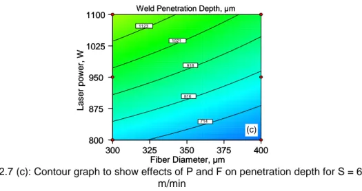
This chapter examines laser beam welding of martensitic stainless steels in a constrained overlap configuration. Experimental investigations are focused on the effects process parameters such as laser power, welding speed, fiber diameter and energy density on the bead geometry and the mechanical properties of the weld. Laser power and welding speed are found to be the most significant factors affecting the weld bead geometry and shearing force. Except on the weld width, fiber diameter has little effect on the aforestated response factors. Nonetheless, combining with other parameters, fiber diameter is found to have significant effect on them. The contour plots showing constant response lines indicate the evidence of two-factor interaction effects of laser power-welding speed, welding speed-fiber diameter, and fiber diameter-laser power on all the response factors except the weld width.
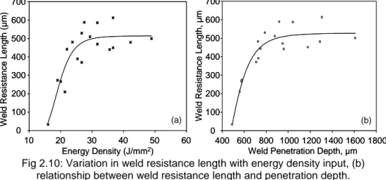
Energy density plots illustrate its linear relationship with penetration depth and limited nonlinear effects on the others. Weld shearing force varies almost linearly with weld resistance length. Both weld resistance length and shearing force are energy-limited. These factors vary positively with energy density input up to a certain limit. After that limit, any additional increase in energy input only increases the weld penetration depth and no longer affects the weld resistance length. As a result, bead profile changes its shape from conical to cylindrical.
Both shrinkage and deformation occur during laser welding. However, amount of shrinkage and behavior of deformation were found unequal and non-uniform respectively for the repeated experiments.
![Fig. 1.2: Variation in heat input with the power density of heat source [2]](https://thumb-eu.123doks.com/thumbv2/123dokorg/7565266.110991/14.723.118.598.211.557/fig-variation-heat-input-power-density-heat-source.webp)