Corso di Laurea Magistrale in Ingegneria Biomedica
CHARACTERIZATION OF HEMODYNAMIC
CONDITIONS IN TESIO AND PALINDROME
CENTRAL VENOUS CATHETER FOR
HEMODIALYSIS
Relatore: Prof. Gabriele Dubini
Correlatori: Ing. Bogdan Ene-Iordache
Ing. Michela Bozzetto
Tesi di laurea di:
Ravasio Giovanni
Matr. 883268
iii
they are waiting for the organ transplant. This treatment greatly affects patients’ life because they have to go to specialized centres twice or three times a week and undergo dialysis treatment that lasts several hours (on average from four to five). The blood is withdrawn from the patient through a vascular access that is created by the nephrologist based on patient's health status, as well as vascular anatomy and quality. The vascular access of first choice is the arteriovenous fistula (AVF) that has lower risks of complications as compared to any other type of vascular access. Since AVF requires the presence of adequate native vessels and a maturation time of about 40 days, not all patients are suitable for the construction of this vascular access and the first alternative is the graft (AVG). In the case of elderly patients or those with vessels very damaged by pathological conditions, the last possibility is to insert a Central Venous Catheter (CVC). Computational fluid dynamics (CFD) is increasingly used in the evaluation of medical devices for cardio-vascular applications. The high spatial and temporal resolution of this technique and the possibility of studying 3D models, without the expensive efforts in terms of manufacturing time of experimental set-ups, allow a reliable and accurate characterization of the blood flow field. It therefore represents a promising approach to study the effect of some hemodialysis catheter design parameters and compare the performance of different catheters in terms of flow separation and blood recirculation regions.
The main objective of the present thesis work is to set up a reliable method for the characterization of hemodynamic condition in patient-specific conditions, coupling imaging techniques and high-resolution CFD.
Key words: CVC, Palindrome, Tesio, CFD, Boundary conditions, SVC, IVC, IJV, Left
v
effettuare in attesa del trapianto di organo. Questa terapia condiziona parecchio la vita dei pazienti in quanto devono recarsi presso i centri specializzati due o tre volte la settimana e sottoporsi al trattamento dialitico che dura diverse ore (in media dalle quattro alle cinque). Il sangue viene prelevato dal paziente tramite un accesso vascolare che viene deciso in base allo stato di salute del paziente e alle condizioni dei suoi vasi sanguigni. L’accesso vascolare di prima scelta è la fistola arterovenosa (AVF) in quanto garantisce un flusso ottimale del sangue e possiede una minore percentuale di fallimento. Poiché la fistola arterovenosa richiede la presenza di vasi nativi adeguati e un tempo di maturazione di circa 40 giorni, non tutti i pazienti risultano idonei per la costruzione di questo accesso vascolare e la prima alternativa è la fistola con graft (AVG). Nel caso di pazienti anziani o con vasi molto danneggiati dalle condizioni patologiche, la terza possibilità di accesso vascolare è tramite un Catetere Venoso Centrale (CVC).
La fluidodinamica computazionale (CFD) è sempre più utilizzata nella valutazione di dispositivi medici per applicazioni cardio-vascolari. L'elevata risoluzione spaziale e temporale di questa tecnica e la possibilità di studiare modelli 3D, senza gli sforzi dispendiosi in termini di tempo di fabbricazione di set-up sperimentali, consentono una caratterizzazione affidabile e accurata del campo di flusso sanguigno. Essa rappresenta quindi un approccio promettente per studiare l'effetto di alcuni parametri di progetto del catetere per emodialisi e confrontare le prestazioni di cateteri diversi in termini di regioni di separazione del flusso e ricircolo del sangue.
L’obiettivo principale del presente lavoro di tesi è quello di impostare un metodo affidabile per la caratterizzazione delle condizioni emodinamiche in casi specifici per ogni paziente, utilizzando sia tecniche di imaging che tecniche CFD.
Parole chiave: CVC, Palindrome, Tesio, CFD, Condizioni al contorno, SVC, IVC, IJV,
vii
RINGRAZIAMENTI ... i
ABSTRACT ... iii
SOMMARIO ...v
CONTENTS ... vii
1. CLINICAL BACKGROUND ...1
1.1. Renal failure ... 21.1.1. Etiology and classification of CKD ... 2
1.1.2. Epidemiology of ESRD ... 3
1.2.
Dialysis treatment ... 51.2.1. Hemodialysis treatment ... 5
1.2.2. Vascular access ... 6
1.3. Central venous catheter ... 8
1.3.1. Catheterization ... 9
1.3.2. Insertion site ... 10
1.3.3. Temporary and permanent CVC ... 11
1.3.4. Biomaterials ... 12
1.3.5. Coating ... 12
1.3.6. Tip design ... 14
viii
2.2. Tesio catheter ... 29
2.3. State of the art of CFD inside CVC ... 33
2.4. Aim of the study ... 37
3. COMPUTATIONAL MESH CREATION ... 39
3.1. 3D model of the veins ... 40
3.1.1. Overview of geometry used in studied articles ... 40
3.1.2. Description of the geometry chosen ... 41
3.1.3. Reading DICOM files and selecting a Volume of Interest (VOI) 43 3.1.4. Level set segmentation ... 44
3.1.5. Generating the vessel wall surface with marching cubes ... 45
3.1.6. Surface smoothing and conversion to .stl format ... 46
3.1.7. Modified with Autodesk Meshmixer ... 47
3.2. Catheters 3D model ... 49
3.2.1. CVC acquisition ... 49
3.2.2. CVC modelling with VMTK ... 52
3.2.3. Autodesk Meshmixer modifications and final models ... 55
3.3. Creation of complete CVC models ... 58
3.3.1. Extrusion with Solidworks ... 58
3.3.2. Autodesk Meshmixer modification to obtain the final models .. 60
3.4. Volume mesh creation ... 66
3.4.1. Surface thresholding ... 66
ix
4.1.1. Search of appropriate boundary conditions ... 74
4.1.2. Choice of the boundary condition ... 78
4.2. CFD simulation ... 83
4.2.1. Blood rheology ... 83
4.2.2. CFD simulations of Palindrome and Tesio cases ... 83
4.3. Post-processing ... 84
5. RESULTS ...85
5.1. Velocity images of Z-axes slice ... 86
5.2. Velocity 3D streamlines ... 88
5.3. Wall Shear Stress on catheters surface ... 92
5.4. Pressure drop inside the catheters tube ... 96
5.5. Turbulent Kinetic energy ... 98
5.6. Particle tracking ... 101
6. DISCUSSION, LIMITATIONS AND FUTURE
DEVELOPMENTS ...105
6.1.
Discussion ... 1066.2. Limitations ... 108
6.3. Future developments ... 109
xi
Figure 1.1 Hemodialysis circuit ... 6
Figure 1.2 The three kind of vascular access ... 7
Figure 1.3 Different tip design [1] ... 15
Figure 2.1 Palindrome lumen design ... 24
Figure 2.2 Palindrome tip design [2] ... 24
Figure 2.3 Palindrome tip design [3] ... 25
Figure 2.4 Palindrome position inside the body ... 26
Figure 2.5 Palindrome inside the right atrium ... 27
Figure 2.6 Tesio catheter ... 29
Figure 2.7 Tesio tip design [4] ... 30
Figure 2.8 Tesio section and Tesio side hole [4] ... 31
Figure 2.9 Tesio position inside the body ... 32
Figure 2.10 Simulation environment with Niagara catheter in hollow tube [5] .. 33
Figure 2.11 Different catheter tip design [6] ... 34
Figure 2.12 Different catheter tip design [7] ... 35
Figure 2.13 Different catheter tip design [8] ... 35
Figure 3.1 Anatomy of SVC ... 42
Figure 3.2 Scheme of RA, IVC and SVC ... 43
Figure 3.3 Extraction of VOI ... 43
Figure 3.4 Level set segmentation ... 44
Figure 3.5 Surface extracted using marching cubes ... 45
Figure 3.6 Surface before the smoothing ... 46
Figure 3.7 Surface after the smoothing ... 46
Figure 3.8 Final surface after Autodesk Meshmixer smoothing ... 48
Figure 3.9 Basis of Palindrome (117 of 4328) ... 49
xii
Figure 3.13 Total Palindrome scanned ... 50
Figure 3.14 Basis of Tesio Blu (0327 of 5420) ... 51
Figure 3.15 Side hole of Tesio Blu (2486 of 5420) ... 51
Figure 3.16 Basis of Tesio Rosso (0327 of 5420) ... 51
Figure 3.17 Side hole of Tesio Rosso (2486 of 5420) ... 51
Figure 3.18 Total Tesio Rosso and Tesio Blu scanned ... 51
Figure 3.19 Palindrome view in X, Y, Z planes with VMTK ... 53
Figure 3.20 Palindrome reconstruction with VMTK ... 53
Figure 3.21 Tesio Blu reconstruction with VMTK ... 54
Figure 3.22 Tesio Rosso reconstruction with VMTK ... 55
Figure 3.23 Palindrome defects viewed in Autodesk Meshmixer ... 56
Figure 3.24 Palindrome particular view of defects in Autodesk Meshmixer ... 56
Figure 3.25 Palindrome tip: final model ... 57
Figure 3.26 Tesio tip: final model ... 57
Figure 3.27 Palindrome extrusion with Solidworks ... 59
Figure 3.28 Tesio extrusion with Solidworks ... 60
Figure 3.29 Tesio extrusion with Solidworks ... 60
Figure 3.30 Palindrome: creation of the internal hole ... 61
Figure 3.31 Palindrome inner lumen hole ... 61
Figure 3.32 Palindrome weld boundaries ... 62
Figure 3.33 Palindrome: removal of the external catheter surface ... 62
Figure 3.34 Tesio weld boundaries ... 63
Figure 3.35 Tesio: removal of the external catheter surface ... 63
Figure 3.36 Palindrome final model ... 64
Figure 3.37 Palindrome final model ... 64
Figure 3.38 Tesio final model ... 65
xiii
Figure 3.42 Palindrome volume mesh: slice of RA ... 69
Figure 3.43 Palindrome volume mesh: vertical slice of RA ... 69
Figure 3.44 Palindrome volume mesh: view at the exit site ... 70
Figure 3.45 Palindrome volume mesh: slice at the level of SVC ... 70
Figure 3.46 Tesio volume mesh: slice of RA ... 71
Figure 3.47 Tesio volume mesh: vertical slice of RA ... 71
Figure 3.48 Tesio volume mesh: view at the exit site ... 72
Figure 3.49 Tesio volume mesh: slice at the level of SVC ... 72
Figure 4.1 Graph of blood flow velocity in the IVC [9] ... 74
Figure 4.2 Graph of blood flow velocity in the SVC [9] ... 75
Figure 4.3 Tricuspid valve outflow [10] ... 76
Figure 4.4 Dialysis circuit [11] ... 77
Figure 4.5 Matlab script for the interpolation ... 78
Figure 4.6 IVC curve of boundary condition ... 79
Figure 4.7 SVC, IJV_DX and AV_SX curve of boundary condition ... 80
Figure 4.8 Outflow curve from the tricuspid valve ... 81
Figure 4.9 Catheters waveform ... 82
Figure 5.1 Palindrome Z-axes slices of velocity magnitude ... 86
Figure 5.2 Tesio Z-axes slices of velocity magnitude ... 87
Figure 5.3 Palindrome streamlines Time 1.00 ... 88
Figure 5.4 Palindrome streamlines Time 1.18 ... 88
Figure 5.5 Palindrome streamlines Time 1.66 ... 89
Figure 5.6 Tesio streamlines Time 1.00 ... 90
Figure 5.7 Tesio streamlines Time 1.18 ... 90
Figure 5.8 Tesio streamlines Time 1.66 ... 91
Figure 5.9 Palindrome WSS: arterial side ... 92
xiv
Figure 5.13 Tesio WSS: focus on arterial side holes ... 94
Figure 5.14 Tesio WSS ... 94
Figure 5.15 Palindrome pressure drop ... 97
Figure 5.16 Tesio pressure drop ... 97
Figure 5.17 Palindrome TKE ... 99
Figure 5.18 Palindrome TKE ... 99
Figure 5.19 Tesio TKE ... 100
Figure 5.20 Tesio TKE ... 100
Figure 5.21 Palindrome particle tracking: first time step ... 101
Figure 5.22 Palindrome particle tracking: end step time ... 101
Figure 5.23 Tesio particle tracking: first time step ... 102
xv
Table 1.1 Incidence of different causes of CKD ... 2 Table 3.1 CFD articles studied ... 40
xvi
CVC Central venous catheter
AKI Acute kidney injury
CKD Chronic kidney disease
ESRD End-stage renal disease
PKD Polycystic kidney disease
GFR Glomerular filtration rate
KDOQI Kidney disease outcomes quality initiative
VA Vascular access
AVF Arteriovenous fistula
AVG Arteriovenous graft
r-TPA Recombinant tissue plasminogen activator
CLASBI Central line-associated bloodstream infection
CRBSI Catheter-related bloodstream infection
CFD Computational fluid dynamics
SVC Superior vena cava
IVC Inferior vena cava
IJV Right internal jugular vein
RA Right atrium
VOI Volume of interest
VMTK Vascular modelling toolkit
WSS Wall shear stress
1
1. Clinical background
The present chapter contains the physio-pathological aspects of the renal apparatus with particular reference to the vital functions and the conditions in which there are compromised, causing renal failure. Furthermore, the main kidney’s replacement treatments are described, focusing on hemodialysis and the main kinds of vascular access, in particular on central venous catheters. Finally, all aspects that concern CVC are described, starting from catheterization, biomaterials, different tip design and possible complications associated to this kind of medical device.
2
1. CLINICAL BACKGROUND
1.1 RENAL FAILURE
Renal diseases can be divided into three principal categories:
• Acute kidney injury (AKI) results in an abrupt loss of renal function with a corresponding spike in serum creatinine concentration and decrease in urine output; however AKI is a reversible condition [12].
• Chronic kidney disease (CKD), which is characterized by a reduced glomerular filtration rate. This condition is irreversible and causes a complete loss of all renal functions.
• End-stage renal disease (ESRD) is the most devastating condition, which requires either renal transplantation or dialysis [12].
1.1.1 Etiology and classification of CKD
The etiology of renal failure can be quite various and depends upon particular event that initiates kidney damage. In the developed countries the three main causes of CKD are diabetes, high blood pressure and glomerulonephritis, a group of diseases that cause inflammation and damage to kidney’s filtering units. Also inherited kidney disease, such as the polycystic kidney disease (PKD), which causes large cysts formation in the kidney damaging the surrounding tissue, is a diffuse cause of CKD. If uncorrected, any of these events can lead to renal failure [13].
Table 1.1_Incidence of different causes of CKD
CAUSES OF CKD % OF INCIDENCE Un-Known 24.86 Vascular 21.6 Diabetes 20.08 Glomerular nephritis 10.31 Hereditary/inborn 6.97 Partial nephrectomy 6.3 Others 4.37 Systemic 4.25 Not-specified 1.26
3
Table 1.1 shows the incidence of the main pathologies causing renal failure, registered in the Italian report of 2010 (http://www.sinidt.org/web/procedure/protocollo.cfm).
Glomerular filtration rate (GFR) has been accepted as the best index of overall kidney function in health and disease. The guidelines called Kidney Disease Outcomes Quality Initiative (KDOQI) [14] published by the National Kidney Foundation, defined several stages of CKD, which can lead to decreased GFR:
- Stage I: it is characterized by the presence of structural or functional abnormalities of the kidney, initially without decreased GFR (> 90 mL/min/1.73 m2), which over time can lead to decreased GFR.
- Stage II: it is characterized by mild reduction in GFR (60 to 89 mL/min/1.73 m2). At this stage, patients usually have hypertension and may have laboratory abnormalities indicative of dysfunction. This condition can be determined by measurements of serum creatinine levels.
- Stage III: it is characterized by moderate reduction in GFR (30 to 59 mL/min/1.73 m2). This stage is distinguished by the presence of azotemia (nitrogen metabolism) and expressed by an evaluation in serum creatinine and serum urea nitrogen. - Stage IV: it is characterized by severe reduction in GFR (15 to 29 mL/min/1.73
m2). In this extreme stage of CKD, the worsening of azotemia, anemia and other laboratory abnormalities reflect dysfunction in several organ systems.
- Stage V: it is characterized by kidney failure (GFR, <15 mL/min/1.73 m2). In most cases, this level of kidney dysfunction is accompanied by a constellation of symptoms and laboratory abnormalities in several organ systems. Kidney replacement therapy (dialysis or transplantation is typically required.
1.1.2 Epidemiology of ESRD
End stage renal disease is a growing global health problem, strictly connected with progressive ageing population and increased survival rate of CKD patients. The number of patients being treated for ESRD globally was estimated to be 3.700.000 at the end of 2016 and, with a ~6% growth rate, continues to increase at a significantly higher rate than the world population. In the US, Japan and the European Union, dialysis
population growth rates are significantly lower than the growth rate in regions such as Asia, Latin America, Middle East and Africa. This variation in growth rates may be
4
partially explained by differences in demographics and the maturity of dialysis programs in developed countries.
The survival alternatives for a patient suffering from renal failure are chronic dialysis treatments (either hemodialysis or peritoneal dialysis) and renal transplantation.
Worldwide, hundreds of thousands of patients are currently treated with dialysis due to the limited number of donors.
5
1.2 DIALYSIS TREATMENT
The first historical description of the dialysis procedure was published in 1913. Abel, Rowntree and Turner “dialyzed” anesthetized animals by directing their blood outside the body and through tubes with semi permeable membranes [5]. George Haas, a German doctor, was the one who performed the first attempt of dialysis involving humans. Thanks to the technical improvements in the equipment, in 1945 Willem Kolff performed the first successful dialysis treatment [6]. Doctor Kolff’s success proved the usefulness of the concepts developed by Abel and Haas: the separation of substances and the removal of water from solutions through semipermeable membranes (diffusion and osmosis processes).
There are two main types of dialysis:
• Hemodialysis: it uses an extracorporeal circuit with a special filter to clean the blood of the patient;
• Peritoneal dialysis: this treatment uses the peritoneal cavity in the abdomen as a reservoir for the dialysis solution and the thin membrane lining this cavity as a suitable barrier through which blood can be filtered.
Nowadays, hemodialysis is the most common treatment, with approximately 2.106.000 patients undergoing hemodialysis (89% of all dialysis patients) and about 252.000 patients undergoing peritoneal dialysis (11%) [15].
1.2.1 Hemodialysis treatment
Dialysis is the therapy which substitute transplants. It consists in a process of blood purification which is made using a semipermeable membrane (biological or artificial) which allows the selective passage of determinate substances between two fluid: the dirty blood and the dialysis fluid. The most common and used kind of dialysis is the hemodialysis. This therapy allows the blood depuration thanks to an artificial filter called dialyzer put inside of an extracorporeal circuit. Blood arrives to this machine thanks to a pump and it begins to circulate in the circuit; when it enters the dialyzer, thanks to different concentration of certain substances (like Na, K, Ca), the dialysis fluid purifies blood which leaves waste substances and recovers the other it needs. When the blood is purified, it returns to the patient’s body thanks to another pump of the same machine.
6
This therapy must be done in dedicated factories (like hospital or Dialysis Centers) from once or twice or three times for week; a single therapy lasts four or five hours depending on the volume of blood that must be purified and the patient condition.
1.2.2 Vascular access
Dialysis machine is attached to patient’s body through a vascular access (VA); from this access, blood comes out from the patient’s body, it passes throughout the dialysis machine and it returns to the patient by the same access after the depuration [15]. Clinical and instrumental evaluation is necessary to identify the type of VA, the medical and technical approach and a good follow up to check complication as early as possible. The major problems and causes of failure in hemodialysis is represented by the lack of good vascular access.
7
There are three main type of VA:
a) The native arteriovenous fistula (AVF). It consists in a surgical connection between an artery and a vein of the patient, usually in the arm and is the first choice for vascular access. However, AVF needs a maturation time (around 40 days) before needles can be inserted in it and can be created only in presence of suitable native vessels. Therefore, despite being the preferred VA due to lower infections and biocompatibility problems, it is not possible for all patients in need of HD treatment.
b) The prosthetic arteriovenous graft (AVG). It consists in an arteriovenous fistula made with prosthetic (graft) interposition between an artery and a vein. This is a good option for patients that had a lot of previous operations and they exhausted superficial veins or it is choose for patients with vascular fragility [16]. However, AVG presents more complications than AVF in terms of vascular stenosis and consequent thrombosis.
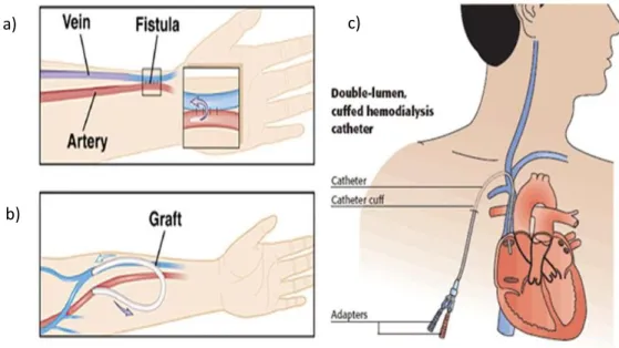
c) The central venous catheters (CVCs). It is the last choice, but always selected in case of need of urgent hemodialysis. Being the focus on this thesis, CVC is widely described in the next paragraph.
Figure 1.2_The three kind of vascular access
a)
b)
8
1.3 CENTRAL VENOUS CATHETER
Central venous catheter represents one of the most important advances in medicine; this medical device become common in the 1967 [17]. It is very used for patients who present malfunction of the permanent access or when they need immediate dialysis therapy and they can not wait for all the AVF or AVG. Its implantation is easier than AVG and AVF: it takes at least 60 minutes and the HD can be effectuated since the day after this operation because of the immediate access to circulation of catheters. Despite of central access catheters allow an adequate blood flow rate, CVCs are evaluated as the third choice for vascular access because they are more subject to infection, vascular stenosis and thrombosis as compared to AVF or AVG [6]. CVCs are also widely used in critically ill patients or for the older ones; in this way is easily to administer medication, blood products and fluids, for example to obtain blood samples [18]. The requirements for a dialysis CVC are [19] [20]:
- High blood flow rates at moderate pressure drops.
- Minimal trauma to the vein intima to avoid thrombosis and venous stenosis. - Prevention of bacterial migration.
- Resistance to occlusion by fibrous sheathing. - Avoidance of contamination of the catheter lumen. - Avoidance of clotting at the tip or within the catheter. - Biocompatibility of the catheter surfaces.
- Avoidance of lumen collapse under negative pressure. - Avoidance of kinking of catheters segments.
- Physical strength and integrity to avoid disconnections or breaks of any component.
- Resistance to antiseptic agents.
- Placement procedures with minimal trauma, risk and difficulty.
- Radiopaque appearance on X-ray for evaluating location during placement and after use.
There are many types of central vascular catheters and they are divided in categories depending on certain properties: the duration of their use (temporary or permanent), if they are tunneled or non-tunneled, the different biomaterial used, if there is or not a
9
coating and the material used for coat, the lumen and tip design, the number of pipes and the presence or not of side holes.
1.3.1 Catheterization
A careful placement of the CVC is essential to avoid catheter malposition and malfunction or complications related to the patient such as vessels’ perforation or uncontrollable bleeding [21]. The correct position is evaluated using radiology instrument: the tip of the catheter must be positioned in the center of the right atrium (RA) for a correct functioning; with the radiology support, doctors can check the right position of the catheter. The catheterization may cause complications immediately after the catheter placement, such as:
- Pleural puncture: pneumothorax and hemothorax are frequent when the needle inadvertently punctures the pleural space; this complication can be recognized by a final spot radiograph of the whole chest.
- Arterial puncture: this complication can be avoid using ultrasound guidance and an identification before preparing is necessary to individuate potential issues. - Bleeding: is very uncommon but if it happens, especially in the entry sites of CVC,
it can be ameliorated with pressure.
- Arrhythmias: some accidental movement of the tip may irritate the atrioventricular node and produce supraventricular tachycardias. Despite all, this inadvertent movements are not common and can be avoid by experience.
- Air-embolism: the technological advances have decreased the rate of this complication; air-embolism is mostly related to the uncorrected position of the patient.
- Laceration of central veins: it is sufficient a close attention during the procedure on insertion to avoid the risk of laceration.
The most common technique for insertion is called “Seldinger Technique”, in honor of the surgeon who developed it in the 1953 [22] [23]. The technique is composed by six steps:
1) A cutaneous cut with a trocar or a scalpel
2) Positioning the metallic guidance, which is a thine metallic wire 3) The trocar is withdrawn
10
4) Insertion of a dilatator to avoid a sudden admission of the catheter which may cause a serious injury of the vessel. Depending on the dimension of the catheter’s lumen, it may be necessary to insert one or more dilatators before the CVC 5) Now the CVC can be positioned inside the patients and using the wire as a guide.
When the catheter reaches the correct position, the wire is withdrawn
6) The area of insertion now can be checked to avoid any complications and it is well covered to decrease the risk of infections.
1.3.2 Insertion site
Preferable location for insertion is decided by instrumental analysis, usually using ultrasound, and thanks to the surgeon’s ability and experience. There are four main location for the access [16]:
- Internal jugular vein: it represents the first choice for central venous catheter; the ultrasound guidance is very recommended to delete the risk of carotid puncture. This vessel is a large superficial vein; its straight course into the superior vena cava (SVC) and then inside the right atrium represents an important factor of choice. For this insertion, the patient must be optimally positioned: he lays down on the operating table with a 10° head-down tilt. An extreme rotation of the head has to be avoided because it may reduce vein diameter [24].
- External jugular vein: this vein may be chosen as an access thanks to its superficial course, so the cannulation is possible without using ultrasound guidance. The most common complication are subclavian-vein stenosis and thrombosis.
- Subclavian vein: it is considered the third choice because the risk of subclavian thrombosis is very high with complication to create a vascular access in the ipsilateral arm. So, this hemodialysis access should not be chosen if there are other central veins that can be punctured. If it is the only possibility of access, it’s recommended to position the patient in the correct way to decrease the risk of air embolism and to help the distension of the vein. The main disadvantages are more risk of bleeding, pneumothorax and thrombosis.
- Common femoral vein: it is considered the second choice for inserting short-term dialysis catheter because the risk of bleeding is lower and is not required a
11
radiological control after the insertion. the main complication in comparison to other access is the higher frequency of catheter-associated bacteraemia.
In conclusion, the favorite location for insertion, in particular for permanent dialysis catheters, is the internal jugular vein because of the lower incidence of complication during the operation and also for the straight course to the right atrium. Moreover, the doctor may choice the right internal jugular vein (IJV) or left internal jugular vein depending on the vessels and patient conditions and the catheter length. However, the surgeon establishes the insertion point according to his experience and his preferences.
1.3.3 Temporary and permanent CVC
The principle distinction is between temporary (fewer than 3 weeks) and permanent catheters; the choice should be based on factors like duration of use, patient conditions and the therapy needed. The permanent catheters are also called “Tunneled” because, after the insertion inside the vein, the catheter’s course is moved under the skin to modify its exit position, usually just above the right nipple; this modification helps to prevent bacteremia and allows the patient a better quality of life [17]. The temporary catheters, instead, are usually called “Non-tunneled” because they are inserted directly in the vessel and they do not pass under the skin.
Temporary catheters are different because they are easier to place and remove [25]; there are also difference as regards the size because they are smaller than the permanent ones. Temporary catheters could be made up with three distinct lumen: the three-lumen design is required for patients who need urgent hemodialysis; the addition of the third lumen is helpful to allow concomitant administration of antibiotics, fluids or other medicines without the necessity of new access [21]. Temporary CVCs are used for acute renal failure, usually in bed-bound patients and for a short-term use in those patients with unexpected malfunction of permanent access [15].
Long-term tunneled catheters are inserted both after a previous temporary catheter’s installation using the same entry site or with the creation of a new access. They are larger than the temporary ones and they present a bonded cuff used to anchor the catheter to the subcutaneous tissue near the exit site of the catheter [25]. The cuff is also important because allows for fibrous sealing of the exit site; this barrier helps to prevent bacterial migration [15].
12
1.3.4 Biomaterials
The materials usable for CVCs must have some characteristics such as other medical devices: they must be biocompatible, hemocompatible, biostable, resistant, flexible, chemically neutral, deformable, resistant to sterilization and not affected by administered drugs [26].
Today, biomaterials used for CVC construction are silicone and polyurethane but is common to use copolymers such as polyurethane/polycarbonate copolymer. Silicone and polyurethane are both biocompatible and durable and there is no significant difference between overall duration of their function [15].
Thermoplastic polyurethanes catheters are composed of long-chain linear polymers without cross-links that are dimly bonded at room temperature, but they become free to slide past one another under the thermal energy provided by the inside of the body. The main characteristic that thermoplastic polyurethane has is that catheters may be manufactured with a higher inner lumen keeping the same outer diameter; in this way the overall catheter flow rate is improved. The main disadvantage of thinner walls is that they allow polyurethane catheters to be more prone to kinking [15] but the catheters can have a larger internal diameter without sacrificing flexibility inside the body and rigidity outside [25].
In vitro comparisons between silicone and polyurethane catheters to establish which is the best remain inconclusive. Animal models appear to attribute a decreased infection risk and thrombogenicity to polyurethane catheters over the silicone ones [27] [28]. The more difficult manufacturing process of silicone catheters may cause a greater propension to construction failures [29] [30].
Although catheter materials such as silicone and polyurethane are chosen to be biocompatible and hemocompatible, complications due to infections and thrombosis are still ineluctable [25]. However, for long-term catheters, polyurethane remains the best choice for catheters material due to the easier manufactures process that needs and the greater inner lumen provided by thinner walls.
1.3.5 Coating
To reduce the risk of complications due to thrombosis or infections or microbial colonization, it is possible to use antithrombotic and antimicrobial surface technologies
13
on catheters. Therefore, some catheter materials can be modified and coated with antibacterial and/or antithrombotic agents [31]. Using antithrombotic coatings there is a reduction in platelet adhesion, an inhibition of inflammatory response and a reduction in thrombus formation; antimicrobial materials, instead, reduce bacterial colonization and the incidence of bacteremia [32]. The most common catheter coatings consist in heparin, antibiotics and silver to minimize thrombosis and infections; antimicrobial coatings help to decrease microorganism adhesion and biofilm formation, so the risk of infection could be reduced.
A first type of material coating is heparin: it is a polysaccharide anticoagulant which exerts its anticoagulant effect by binding to antithrombin, then forms a complex with thrombin; this complex, formed by heparin, antithrombin and thrombin, inactivates thrombin, inhibiting its ability to convert fibrinogen to fibrin [33] [34]. Heparin coating covers both internal and external catheter surface and it is covalently bound to the polyurethane surface of the catheter material through an end-point linkage mechanism [35]. However, the flow characteristics between the uncoated and the heparin-coated are very similar and catheters with coating do not show a significant increase in catheter patency compared to uncoated catheters [35].
Another common coating hemodialysis catheter is the one with antibiotics; those catheters are impregnated with minocycline and rifampin and this coating provided antimicrobial activity on the luminal and abluminal surface. This method provides good result especially in short-term central venous catheter thanks to the half-life of antibiotic minocycline and rifampin [36]. In long-term catheters, a coating like this is not used because it will not provide good results in the long period.
The most common material coating with antimicrobial effect is silver, especially nanoparticles of silver. It is known that silver has strong biocide activity against a wide range of bacteria and it is a good biocompatible material [37]. The biocide activity of silver consists in inducing the inhibition of bacterial DNA replication and the deactivation of metabolic enzyme [38] [39]; in particular, silver nanoparticles have demonstrated strong antibacterial activity [40]. Silver is applied on the catheter using a process based on the deposition of nanoparticles using UV irradiation [41] that provides a uniform deposition and distribution of silver on the external surface. The catheter is immersed in
14
a 0.1% solution of silver-nanoparticles; this value represents the best compromise between the manufacturing costs and the results provided by antibacterial activity [42].
1.3.6 Tip design
The concept of “catheter functional tip” has been developed recently; tip is the part of the catheter from the most proximal side hole to the catheter tip; this part of CVC established the main differentiation between different catheters. For a correct functioning of central venous catheters, CVC tip may be positioned in the center of the right atrium and there it should stay because this position provides an adequate blood flow rate. Wrong positioning may cause venous stenosis and recirculation problems and then malfunctions in dialysis therapy, or may irritate the internal surface of the right atrium and cause arrhythmias, most commonly atrial ectopics [15]. To improve the possibility of avoiding blood recirculation, some catheters present side holes near the exit lumen; side holes can decrease the overall resistance and provide a more disturbed flow patterns near the wall and consequently a better washout near the internal wall [6]. They also provide a back-up blood path when the end hole is obstructed by a fibrin sheath or a blood clot [5]. However, their main goal is to allow the catheter in the right position at the center of the superior vena cava, avoiding the catheter surface to stick along the vessel internal wall. Number and size of side holes play an important role in blood recirculation [8]: an excessive number and size value may reduce significantly the blood flow rate from the main lumen and then causes dialysis malfunction. Their presence may promote complications due to thrombosis or creation of relative dead space at the end of the tip promoting clotting [19]. Concerned for long-term dialysis catheter, side holes provide a good method for keeping tip in the right position despite their related complications. Over the years, many catheter tips have been designed and developed to have always a better dialysis functioning. First of all, researches for the best biomaterial allow CVC tips to be relatively rigid at room temperature to facilitate insertion, but inside the body tips become softer to minimize the potential vessel trauma [31]. Several modifications of the catheter tip design have been implemented including twin catheters, single body step-tip, split-tip and single body symmetric-tip designs. Split-tip design improve average dialysis blood flow rates compared with single body step-tip catheters but the difference is
15
relatively small [43]. Symmetric-tip catheters are designed to reduce recirculation and resist growth of undesired fibrin sheath [21].
In the figure 3, there are illustrated some different models of catheter tip.
1.3.7 Complications
CVC are medical devices which can be subject to many complication despite their relatively basic structure. Complications can be divided into two main groups:
- Short-term complications, which occurs suddenly after the catheter placement, in the first dialysis session therapy or within the following 30 days;
- Long-term complications, which occurs after at least 30 days following the placement.
If any complications do not appear, CVC’s life expectative is very high: some type of tunneled and cuffed central venous catheters can survive for 8-9 years inside the patient body; the duration is influenced by patient’s health state and the care with which the catheter is treated. Hemodialysis catheter are handled only during dialysis session with no irrigation between treatments. According to standard nursing procedures, the catheter exit site is cleaned with a solution and covered with permeable dressing at the end of each
16
dialysis session. Each time before the catheter is opened, its end-part is carefully checked for any redness, swelling, bleeding or exudate and patients should report any fever episodes [44].
There are a variety of definitions for catheter dysfunction; the National Kidney Foundation Dialysis Outcome and Quality Initiative (KDOQI) defines catheter dysfunction as failure to attain and maintain an extracorporeal blood flow of 300 mL/min or greater at a pre-pump arterial pressure more negative than -250 mmHg [45].
Short-term complications: this type of complications are usually similar to the ones that occurs during catheter insertions and described above in the part “catheterization”. Early complications that have a frequency lower than 2% are:
- Hemorrhage or hematoma; - Catheter malposition or kinking; - Venous perforation;
- Infection;
- Arterial puncture; - Pneumothorax; - Air embolism.
Catheter malposition is a typical complication in patients who have vessels in a poor condition: this happen because the course from their insertion site, that usually is internal jugular vein, to the center of right atrium is not so defined as in healthy patients. With bad conditions of vessels internal wall, CVC can proceed in a wrong direction as inside the pulmonary vein or the carotid artery. The doctor prevents this kind of complications using ultrasound guidance and with his experience; to check if the catheter is in the right position, at the end of the surgical operation a radiological control with x-ray is needed. So, early catheter dysfunction generally occurs as a result of mechanical issues such as patient malpositioning, mechanical kinking of catheter and incorrect tip location [46] [47]. To reduce the risk of dysfunction it would be better following the precaution techniques described just above. This type of problems can be resolved by repositioning the patient or adjusting the patient’s neck position, which may fix a kink or move the catheter tip away from a vessel wall [48]; to solve the problem of reaching the right atrium, the doctor should try to move carefully the CVC inside patient vessels.
17
Long-term complications: late dysfunctions refer to any catheter that previously functioned well but then later becomes dysfunctional, also weeks, months or even years after its insertion. These complications are:
1. Fibrin sheath: it begin to form within 24 hours of catheter insertion; the fibrin sheath is a membrane substance consisting of endothelial cells, smooth muscle cells, collagen and a combination of fibrinogen, lipoproteins, albumin and coagulation factors [49] wrapping around the central venous catheter. The sheath may partially or completely encase the catheter, extending beyond the catheter tip, leading to the disturbance of catheter blood flow [48]. The fibrin sheath begins at the point of contact between the vessel wall and the catheter and it can advance until it covers the whole length of the CVC.
The appearance of this sheath is related to the presence of biofilm; indeed, 100% of fibrin sheaths are colonized with bacteria. This biofilm is characterized by cells that attach themselves to a substratum or to each other; those cells are protected bay an extracellular matrix of substances that they produce themselves. The greatest complication of the biofilm is the development of the fibrin sheath that is the most important noninfectious complication; however, the presence of biofilm does not necessary cause the infection [32]. The presence of fibrin sheath complicates also the total replacement of central vascular catheters: total removal of failed CVC is a complicated and risky surgical operation because the doctor can not previously know how much fibrin sheath is extended; this operation can cause uncontrolled bleeding and lead in extreme cases to patient death.
The catheter can be infected in two ways, depending on the time it has remained inserted: first, within the firsts 30 days after placement, infection occurs mainly due to cutaneous microflora, the care staff’s hands and thanks to internal routes; this biofilm develops a high resistance to systemic antibiotics [50] [51]. Second, dysfunction usually appears 90 days after placement [52].
Anticoagulant lock is the most commonly used preventive measure during the interdialytic period; usually heparin or citrate are used for the anticoagulant therapy.
To avoid the formation of biofilm, the ideal catheter should be biocompatible, prevent fibrin sheath formation, have a long-term effect and a wide range of
18
antimicrobial activity without producing resistance [53]. A strategy to reduce infections and function problems may be catheter coating with particular elements such as nanoparticles of silver, heparin, rifampicine and minocycline or chlorhexidine and silver sulfadiazine. Those anti-microbial coated catheters are expensive, so the doctor uses them only in particular cases such as young patients with a high life expectancy.
2. Thrombosis: it can occur in both early and late catheter dysfunction, although more commonly associated with late dysfunction [48]. Intrinsic catheter thrombosis occurs when a thrombus is formed and attached to the inner or the outer surface of the catheter. Extrinsic catheter thrombosis occurs when a thrombus is caused by the presence of catheter in the atrium of central vein [44]. This complication is recognized by the inability to aspirate or flush a catheter and all the thromboses are related to fibrin sheaths [21]. Other parameters which help to recognize thrombosis are maximal consistently achievable blood flow rate, resistance to blood flow during hemodialysis, insufficient depuration despite adequate session length.
For thrombosis prevention, the most commonly used anticoagulation locking solutions are heparin (1000 to 5000 U/mL) and trisodium citrate (4% to 47%) [54]. Comparison of citrate and heparin locks yielded similar results with citrate that has been associated to lower bleeding complications. Recombinant tissue plasminogen activator (r-TPA) is the most commonly used thrombolytic agents lock improves blood flow rates, lowers venous pressures and reduces complications [55]. The r-TPA is allowed to dwell for 1 to 4 hours and this treatment consists of filling the lumen of the catheter with this agent. If this fails, exchange of the catheter is the recommended solution.
Thrombosis of vessels around the catheter is more serious and is usually related to hypercoagulable states or poor tip position; vascular thrombosis is believed to be related to fibrin sheaths development. Intravascular thrombosis is usually asymptomatic and the only way to recognize it is by observing a catheter malfunction [21].
3. Central Venous Stenosis: this complication may occur after damage to the vein wall due to infection or mechanical failure. The risk of stenosis is limited if the
19
catheter lies in the center of a big vessel with a high blow flow; so, it is strictly related to right positioning of CVC. Stenosis of the central vein can cause obstruction syndrome, which in turn results in a series of symptoms and signs including swelling of the limbs, head and neck after stenosis of the vena cava systems, ulcers and infections of the limbs, and cerebral edema in severe cases [44]. For diagnosis, an angiography is required to confirm the location and extension of the obstruction.
4. Tip Malposition: tip position outside the right atrium may lead to fibrin sheath formation, thrombosis and central venous stenosis, as a result of poor flows or occlusion.
5. Catheter malposition or kinking: it occurs when the catheter is positioned in the wrong place or moves after being placed, or the CVC is curved or folded [44]. To prevent this complication, is recommended a radiological control at the end of positioning.
6. Catheter-related infections: central line-associated bloodstream infection (CLASBI), called also catheter-related bloodstream infection (CRBSI) is the most serious and common complication related to central venous catheters [56]. For this reason, CVCs are the third choice for hemodialysis vascular access: AVF and AVG are preferred for their lower infection risk. Infection is responsible for the removal of about 30-60 % of all hemodialysis CVCs, and it is the second cause of death in dialysis after cardiovascular events [32]. Infection is defined as any of the following [36]:
• Catheter-associated bloodstream infection; • Catheter-related bloodstream infection; • Catheter-related sepsis.
CRSBI is dependent on the length of time the patient has the catheter inside his body and other factors, such as patient hygiene and precautions taken by the dialysis nurses during dialysis and the physicians during placement [57]. Catheter-related bloodstream infection is associated with high rates of morbidity and mortality with an addition of excessive costs to the care of patients [58]. The chance that a patient with central venous catheter may have developed CRSBI must be take into account in case of fever, shivers or hypotension; it is also
20
diagnosed if pus, redness, tenderness and/or induration greater than 2 cm along the catheter is present [44]. Most of the diagnostic methods use quantitative or semi-quantitative cultures taken both from the CVC and from a peripheral vein [59].
The risk of infection increases in relation to the insertion site: femoral catheters is associated with a higher rate of thrombosis and infection; subclavian access is preferred for infection control purpose but other factors, such as potential mechanical complication, thrombosis and operator experience should be considered and decrease the choice rate of this access [60] [61]. So, the choice of internal jugular vein is the right compromise between potential mechanical complication and risk of infection of this insertion site.
There are different type of catheter-related infections and their management varies due to severity [62]:
• Exit site infection without discharge or any symptoms involves only the exit site and not the CVC. This can be treated with catheter exchange alone from the same exit site.
• Exit site infection with discharge or local symptoms should be treated with catheter exchange with creation of a new tunnel, but the same insertion site can be used. An antibiotics therapy should follow depending on cultures and sensitivities of pus discharge.
• Tunnel infection should be treated with removal of the old catheter and insertion of a new catheter at a new venotomy and exit site.
• Catheter-related bacteremia is defined as signs of catheter infection and bacteremia with two sets of positive blood cultures. The treatment should be a removal of the catheter followed by a course of antibiotics broad spectrum at first and more specific after the culture.
In patients with tunneled hemodialysis catheter it is preferred to try keeping inside the body the CVC and start an antibiotic therapy due to the difficulty and high risk of complication of removal operation. Even though the CVC substitution is clinically advised, before the removal of a catheter it is necessary to make sure that a new site is available for insertion of a new catheter; otherwise, due to the surgeon’s decision, the new catheter may be inserted in the same access site. If the
21
decision of the clinical team is maintaining the catheters inside the patient, a possible therapy to remove the infection is the antibiotic one. The ideal antibiotic for the treatment of hemodialysis CRBSI must [15]
• Be active towards those pathogens that are usually responsible for infection;
• Have a fast bactericide action;
• Have concentration-dependent action; • Not be cleared via the kidneys;
• Have a long biological half-life that allows a single, daily administration after hemodialysis;
• Have a good capacity of penetration into the biofilm.
Some preventive measures for decreasing CRBSI rate are surveillance, education and quality management strategies, antiseptic dressings and catheter locks. The standard of care for infection prevention must continue to include the use of sterile gloves, a long-sleeved sterile gown, a mask, a cap and large sterile drapes during catheter insertion. Skin disinfection with 2% alcoholic chlorhexidine significantly helps to diminish the risk of presence of micro-organisms on the skin surface. During the catheterization, practical recommendations for care and surveillance include three general preventive measures: prevention and control of multi resistant bacteria spread, surveillance of nosocomial infections and hand hygiene [63].
23
2. Hemodynamics inside CVC
The present chapter contains the description of the two central venous catheters, Palindrome and Tesio, that characterized this thesis work. Furthermore, is described the state of art of the studies already present in literature which dealt with the computational fluid dynamics of CVC. Finally, is expressed the aim of the present study.
24
2. HEMODYNAMICS INSIDE CVC
2.1 PALINDROME CATHETER
PalindromeTM is a catheter used for the hemodialytic treatment; it belongs to the Palindrome precision family of chronic hemodialysis catheter, namely the group of CVC that has a particular tip design. Palindrome catheter was developed in 2005 [64]; this catheter consists in only one tube made of Carbonate (which is an aliphatic polyurethane group, based on polycarbonate) and divided in the middle to form two symmetrical “D”-shape lumen, one for the arterial needle that conducts “dirty blood” from the patient to dialysis machine, and the other for the venous needle that brings dialyzed blood from the dialysis machine to the patient.
Figure 2.1_Palindrome lumen design
25
The main particular that characterized this group of catheters is the symmetrical “Z” shape tip [65]: it is designed with a symmetric, spiral tip and biased ports, with only two side holes, one on each side. The presence of side slots is due to reduce the likelihood of positional occlusion.
The choice of a symmetrical tip design is based on the research of recirculation risk reduction. The geometry of Palindrome tip is such that the inflow is mostly through the side hole situated about 2 cm proximal to the tip (the one indicated by the blue arrow in figure 6) and also through the most proximal part of the spiral end hole (right above the side hole) [2]. The outflow, which consists in dialyzed blood, is directed away from the catheter mainly through the spiral end hole (indicated in the figure 6 by the red arrow). This design, in addiction with the septum between the catheter lumens, would prevent recirculation: Tal et al. [3] ( Journal of Vascular and Interventional Radiology, 2005) conducted an animal study using a swine model: the Palindrome catheter demonstrated a reduced rate of recirculation compared with other catheters.
This study is also important because it treats a fundamental aspect that characterized Palindrome catheter: the possibility of inverting arterial lumen with the venous one due to his perfect symmetry. The authors demonstrated that, even with reversal of the dialysis lines, minimal recirculation characterizes Palindrome catheter.
In addiction to the reduction of recirculation, this catheter was developed with the purpose of reducing catheter-related complications, such as fibrin sheath and infection) by
26
reducing thrombosis: Spector et al. [2] (Journal of Vascular and Interventional Radiology, 2008), after their single institution study, came to the conclusion that Palindrome catheter demonstrated safe and reliable use with low infection rates.
The Palindrome dialysis catheter is able to guarantee high flow rates (between 300 mL/min and 600 mL/min) due to its internal lumen design, with a diameter of 14.5 Fr (French is the measurement unit used for tube diameter; 3 Fr = 1 mm), and durable Carbothane™ material [66]. This high tensile strength material and the catheter internal lumen design optimize inner diameter integrity without compromising flexibility or kink resistance, so the internal lumens keep maintaining their “D” shape.
Several authors conduct clinical studies with the purpose of establishing which catheter was better: Hwang et al. [64] (Seminars in Dialysis, 2012) conducted a prospective randomize trial with a comparison of the Palindrome vs. Step-Tip tunneled hemodialysis catheter. They noticed that Palindrome catheter have advantages in terms of lower catheter dysfunction rate, lower recirculation with reversed blood lines, higher short-term catheter survival rate.
Li et al. [65] (Iranian Journal Kidney Diseases, 2014) arrived at the conclusion that for dialysis patients studied, Palindrome catheter was superior to Permcath catheter and comparable with the AVF in terms of the maximum blood flow, dialysis adequacy, and annual patency rate.
Ye et al. [67] (Informa Healthcare USA, 2015) conducted a retrospective study of 284 cases of chronic catheterization in 271 patients treated between 2009 and 2011 using
27
Palindrome symmetrical-tip or Permcath step-tip: Palindrome catheter was associated with a longer mean dwell time, lower incidence of low blood flow, and lower infection rate compared with the step-tip catheter.
As for other hemodialysis catheters, the optimum Palindrome tip position is the center of right atrium; this condition could be reached thanks to the metallic guide used during catheterization (specified above) and the ability of the nephrologist. The insertion procedure takes on the average 20 minutes; the duration mostly depends on the ability and the experience of the inserter. In addition, Palindrome helps nephrologist with a radiopaque tungsten marker band, positioned proximal the side holes, that allows to distinguish catheter’s tip and to visualize the correct placement in the right atrium on fluoroscopy and X-ray.
Concerning catheter’s tip, it is fundamental the fact that it is made with the laser cut technology: this technique allows to produce the Palindrome tip with the best possible accuracy. In particular, the laser-cut side holes have been enhanced to reduce total shear
28
stress on the inflow side slot and laser-cut surfaces help to discourage platelet adhesion and minimize debris attachment.
Palindrome precision family of chronic hemodialysis catheters includes several type of CVC that differ from each other for some particular [66] :
- Palindrome Precision symmetric tip dialysis catheter: is the basis one, with the marker band technology, the laser-cut side holes and without coating;
- Palindrome Precision H-heparin coated dialysis catheter: noneluting heparin coating decreases the likelihood of platelet adhesion and inhibits fibrin sheath formation;
- Palindrome Precision SI-silver ion antimicrobial dialysis catheter: a silver ion sleeve reduces colonization against a broad spectrum of bacteria on the catheter surface;
- Palindrome Precision HIS-heparin coated and silver ion antimicrobial dialysis catheter: both silver ion sleeve and heparin coating are incorporated into the catheter due to reduce the likelihood platelet adhesion and colonization against a broad spectrum of bacteria;
- Palindrome Precision RT-reverse-tunneled dialysis catheter: reverse-tunneled catheter tip is designed to allow for precise tip and cuff placement using the retrograde tunnel technique.
29
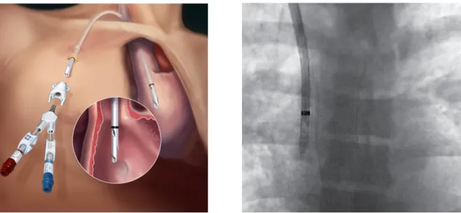
2.2 TESIO CATHETER
Tesio Cath is the second type of central venous catheter studied in this work: it is a kind of vascular access that allows accessing blood for dialysis. Its main particularity is the presence of two identical tube made up with the same geometry and material.
It was studied and designed by Franco Tesio: around 1980 he developed his first hemodialysis permanent catheters, which had the main problem regarding the material: he used common silicone but it was inadequate for the long-term treatment [68]. Driven by the purpose of solving this problem and other regarding mal-positioning and catheter’s conformation, Tesio developed a new type of catheter, implanted for the first time in 1986. It was very similar to the one of our days: two catheters inserted both in the right internal jugular vein with the tip positioned in the center of the right atrium. The material was the spi-silicon, studied by Suzuki and Bambaur; now the material mostly used for Tesio Cath is the Bio-Flex (which gives the name Bio-Flex Tesio Cath, Medcomp) which is a carbothane with higher performance in flexibility and kinking resistance.
The presence of two distinct tube, one for the arterial line, which brings the “dirty” blood from the patient to the dialysis machine, and the other for the venous line, which brings the dialyzed blood to the patient, allows to place the two tip in the as correct as possible position, focusing on one at a time. Furthermore, if one of the two catheters went into failure, it is possible to substitute only the failed one with a new catheter, while the other tube is letting work; in this way, the dialytic therapy must not be suspended [68].
30
Each tube of Tesio Cath has a diameter of 10 Fr (that is equal to 3.3 mm): this allows an adequate flow rate for the dialysis therapy; the internal lumen keeps the circular shape for all the catheter’s length.
Concerning the tip, both catheters have the same identical geometry: a huge hole at the end of the tube but also six side holes spirally placed starting from the exit site [4]. Each side hole has a diameter of 15 mm and they make the catheter tip approximately 50 mm long.
The side holes have the task of avoiding that the final part of the tube will attach to the internal wall of the vein and letting an adequate blood flow rate even in case of fibrin sheet formation and the eventual occlusion of the end site or someone of the side hole.
31
For Tesio Cath is fundamental that the tip of both catheters must be positioned in the correct way: the optimal position is the same of other catheter (the center of the right atrium); in addition, the venous catheter must be positioned above the arterial one, about 2-3 cm of distance, closer to the tricuspid valve. This reciprocal position of the inflow and the outflow tubes allows to avoid a high rate of recirculation; an eventual malposition could make the dialytic therapy useless. To prevent the risk of uncorrected positioning, the nephrologist must be careful during the procedure: after the insertion of the tubes, he checks by X-ray their position; once observed the result images, he eventually assesses some arrangements to obtain the correct tip position. This condition is maintained due to the cuff previously described that anchors the catheters in the right position.
Figure 2.8_Tesio section and Tesio side hole [4]
32
The procedure of insertion for the Tesio Cath takes more time compared to the one for the Palindrome: due to the fact that Tesio Cath are two different tube, this procedure can last at least 45 minutes.
The inflow, that is the blood flow in the venous line, is mainly through the main hole at the end site and it exploits less the side holes. Instead, the outflow is mainly through the two or three most distal side holes.
There are different type of Bio-Flex Tesio Cath available: they difference each other for the length between the end part of the tip and the cuff position; the correct length is chosen by the nephrologist on the basis of the patient’s size.
33
2.3 STATE OF THE ART OF CFD INSIDE CVC
Computational Fluid Dynamics (CFD) is the numerical analysis of physical phenomenon such as flow of fluids, gases or heat. This analysis technique is increasingly used in developing medical devices and studying their behavior for clinical applications. Indeed, thanks to CFD software, fluid flow problems are analyzed with a huge saving of time because the fabrication and characterization of experimental set-up is unnecessary. A literature research provides a first vision of the studies present which concern the application of CFD techniques to hemodialysis CVC.
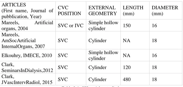
Mareels et al [5] (Artificial Organs, 2004) studied the Niagara catheter using CFD simulation technique. In particular, they studied the influence of side holes in different situations: totally open side holes, totally closed side holes and side holes with reduced size. They evaluated the insertion of the catheter first in a simple hollow cylinder placed concentrically around the CVC (simulating the superior vena cava) and after using a 3D model of right atrium reconstructed from axial cryosection images of a male cadaver. They used CAD package SolidWorks 2000 (SolidWorks Corporation, Concord, MA, U.S.A) to construct the model of Niagara catheter; concerning on CFD simulation, the CFD software they choose to simulate blood flow was Fluent 6.1 (Fluent Inc., Lebanon, NH, U.S.A.).
34
The same authors compared seven CVC designs using CFD simulation [6] (American Society of Artificial Internal Organs, 2007). The different catheter designs studied were Cut straight, Cut straight sleeve, Cut angle, Cut straight hole, Concentric, Cut angle hole and Ash split. All catheter models were constructed in in vivo scale in the CAD package SolidWorks 2003; concerning CFD simulation, catheter models were inserted concentrically in an in vivo-scaled rigid cylinder representing the superior vena cava and the software used was Fluent 6.2.
Elkhoury et al [69] (International Mechanical Engineering Congress & Exposition, 2010) compare the performance of three hemodialysis catheters: Niagara double lumen, Flexxicon II double lumen and Hemosplit long-term catheters in terms of blood flow rate and shorter exposure time, focusing on the comparison of shear rates. For the study, authors used catheter’s geometries constructed with SolidWorks 2007; with this software they also modelled the superior vena cava, in which catheters are placed, with a simple hollow cylinder. The hemodynamics were evaluated using Fluent 6.3 software.
Clark et al [7] (Seminars in Dialysis, 2012) examined flow characteristics of two CVC: VectorFlow catheter and Palindrome catheter. They examined the behavior of these catheters in three settings: a simulated model using computational flow dynamics, a bench model of hemodialysis and an animal model (to measure recirculation at varying rates of flow). Furthermore, they compare the results of this catheter with other dialysis catheter designs, in particular the ones studied by Mareels et al. (2007). In this study, Clark created catheters’ design using SolidWorks software; these virtual catheters were placed within
35
a hollow cylinder representing the superior vena cava. The software used for CFD simulation was Fluent 6.2.
Figure 2.12_Different catheter tip design [7]
Again Clark et al. [8] (Journal of Vascular and Interventional Radiology, 2015) compared three different catheters’ design: Palindrome, VectorFlow and GlidePath. They obtained catheters’ geometry in three different way: Palindrome catheter was measured with a touch probe coordinate machine; to generate a 3D model they used SolidWorks starting from the resultant measurements previously obtained. Concerning to GlidePath catheter, thanks to a high-resolution industrial computed tomography system (GKS Services, Minneapolis, Minnesota) they obtained a scan of internal and external surfaces and the resulting 3D model was rendered into SolidWorks. Finally, the VectorFlow catheter was rendered by using design-control SolidWorks files. To compute CFD simulation, these
![Figure 2.2_Palindrome tip design [2]](https://thumb-eu.123doks.com/thumbv2/123dokorg/7521697.106100/42.893.155.695.823.1094/figure-palindrome-tip-design.webp)
![Figure 2.7_Tesio tip design [4]](https://thumb-eu.123doks.com/thumbv2/123dokorg/7521697.106100/48.893.108.746.348.802/figure-tesio-tip-design.webp)
![Figure 2.8_Tesio section and Tesio side hole [4]](https://thumb-eu.123doks.com/thumbv2/123dokorg/7521697.106100/49.893.124.795.133.381/figure-tesio-section-and-tesio-side-hole.webp)
![Figure 2.11_Different catheter tip design [6]](https://thumb-eu.123doks.com/thumbv2/123dokorg/7521697.106100/52.893.181.661.339.654/figure-different-catheter-tip-design.webp)
![Figure 2.13_Different catheter tip design [8]](https://thumb-eu.123doks.com/thumbv2/123dokorg/7521697.106100/53.893.149.787.904.1098/figure-different-catheter-tip-design.webp)