UNIVERSITY OF CATANIA
Department of Chemistry
International PhD in Chemical Sciences XXX cycle
________________________________________________________
NICOLETTA FRANCESCA
Design and synthesis of new processable materials
for application in organic devices
Final thesis
Coordinator: Tutor:
Prof. S. Sortino Prof. C. Fortuna
I have not failed, I have only discovered 10.000 ways that didn’t work! Thomas Edison
Introduction ... 7
1. Energy demand from alternative sources ... 8
2. Organic polyconjugated compounds: new materials for optoelectronic devices ... 9
3. Organic solar cells... 12
3.1 Architecture of organic photovoltaic devices ... 17
4. Demand of alternative materials in transistors production ... 20
4.1 Organic field effect transistors ... 21
5. Compounds with diketopyrrolopyrrole structure ... 23
Results and discussion ... 28
6. New triazole-diketopyrrolopyrrole derivatives with tunable solubility ... 29
6.1 Synthesis of small molecules ... 31
6.2 Solubility of the small molecules ... 33
6.3 UV-Vis characterization in solution and in the solid state ... 34
6.4 Determination of HOMO and LUMO levels ... 38
6.5 Preliminary tests in solar cells ... 40
7. New conjugated polymers for bulk heterojunction solar cells ... 43
7.1 GPC characterization of the polymers ... 47
7.2 UV-Vis characterization of the polymers ... 48
7.3 Thermal treatment of polymers TegDPPK and TegDPPK1 ... 50
Table of contents
8.1 GPC characterization of the polymers ... 62
8.2 UV-Vis characterization in solution and in the solid state ... 63
8.3 Determination of HOMO and LUMO levels ... 65
8.4 Tests in organic field-effect transistor ... 66
Conclusions ... 68
Experimental section ... 72
9 Solvents and reagents ... 73
9.1 Instruments ... 73 10 Synthesis of 2a ... 75 10.1 Synthesis of TegDPP ... 76 10.2 Synthesis ofTegDPPBr2 ... 77 10.3 Synthesis of 2c ... 78 10.4 Synthesis of 3a ... 80 10.5 Synthesis of 3b ... 81 10.6 Synthesis of 3c ... 82 10.7 Synthesis of 4a ... 84 10.8 Synthesis of 4b ... 85 10.9 Synthesis of 4c ... 86 10.10 Synthesis of 5a ... 87 10.11 Synthesis of 5b ... 88 10.12 Synthesis of 5c ... 90 10.13 Synthesis of 5d ... 91 10.14 Synthesis of 5e ... 93 10.15 Synthesis of 5f ... 94
12.1 Synthesis of the copolymer TegDPPT ... 98
12.2 Synthesis of the copolymer TegDPPBDT ... 99
12.3 Synthesis of 2-(2-(2-methoxyethoxy)ethoxy)ethyl 2,5-dibromothiophen-3-carboxylate ... 100
12.4 Synthesis of the polymer TegDPPTegES ... 101
12.5 Synthesis of 4-(2,3-bis(tert-butyldimethylsilyloxy) propoxy)-2-methylbutan-2-yl 2,5-dibromo-thiophene-3-carboxylate ... 102
12.6 Synthesis of the polymer TegDPPK ... 104
12.7 Deprotection of the hydroxyl groups in the TegDPPK ... 105
12.8 Synthesis of the polymer TegDPPK1 ... 106
12.9 Deprotection of the hydroxyl groups in the TegDPPK1 ... 107
13 Fabrication of TegDPPBDT in BHJ solar cells ... 108
13.1 Fabrication of TegDPPBDT in OFETs ... 108
14 Synthesis of the polymer TegDPPBDT-HMW ... 110
14.1 Synthesis of the polymer EHDPPBDT ... 111
Appendix spectra ... 112
1. Energy demand from alternative sources
The growing energy demand and the gradual exhaustion of fossil fuels have, in recent years, pushed the national governments to adopt energy policies aimed at the exploitation of so-called renewable energy, energy that is derived from unlimited energy sources over time, in order to restrict emissions of pollutants or greenhouse gases. Some examples are hydroelectric, wind, marine, geothermal, solar and biomass produced energy.
Big investments have been devoted to study photovoltaic energy and to development of photovoltaic cells more efficient and economical.
Photovoltaic energy exploits the photovoltaic effect that occurs at the interface of a junction between a p-doped and an n-doped semiconductor (p-n junction).
To date, the monocrystalline, polycrystalline or amorphous silicon form the majority of the photovoltaic modules on the market, with an efficiency of power conversion of the solar spectrum into electrical energy, up to 20-25%. However, the production costs are still thus leading to a cost per watt/hour higher than that supported by burning fossil fuels. Therefore, the only way to make photovoltaic competitive should focus on increasing production volumes and efficiency or on introducing new technologies and new materials.
Introduction
lower, thanks to the reduction of high temperature processes, lower than the melting temperature of silicon (1414 °C), and to the use of lower amounts of semiconductor material. Against a lower efficiency, this shows the significant advantages both as regards the costs, that the versatility of the applications.
The versatility of organic solar cells resides in: i) low-cost technology of production, ii) possibility to be realized with flexible substrates and iii) more easy processability than silicon1. Besides, these materials can be printed
easily on large areas using them as inks, dissolved in organic solvents. The structures can be cut and realized in any size and shape. Furthermore, they form colored and semitransparent films.
2. Organic polyconjugated compounds: new materials for
optoelectronic devices
The classical inorganic semiconductors are characterized by conduction bands, however also a simple organic molecule it is characterized by the
HOMO and LUMO orbitals. Numerous studies show that the formation of a
polymer chain2 determines the approach between them of the empty
orbitals, and in the same way of those full. In this way, the energy gap between HOMO and LUMO levels decreases (figure 2.1).
Figure 2.1: Energy levels calculated for oligomers and polymers.
To behave as semiconductor, an organic molecule must possess a sequence of planar carbon atoms (sp2 or sp hybridization) and each carbon atom bears a pz orbital able to give overlap with the adjacent orbitals.
The energy gap (Eg) is the energy range between the lowest unoccupied molecular orbital (LUMO) and the higher occupied (HOMO): this is one of the most important chemico-physical parameters in determining the opto-electronic properties of a semiconductor, since it is strongly connected to the structure of the polyconjugated molecules.
The many structural changes, allow the fine-tuning of the optical and electronic properties over a wide range, which is currently unthinkable for inorganic materials. Figure 2.2 shows some polyconjugated structures and
Introduction
Figure 2.2: Examples of polyconjugated polymers.
The main factors that allows to modulate the band gap in the polyconjugated compounds are listed below:
1. Structure of the conjugate skeleton 2. Length of the conjugated system 3. Presence of electronic substituents 4. Presence of distortion
5. Inter-chain interactions.
Roncalì3 rationalizes these effects in the following equation:
Eg = Eres+Eδr+Esub+Eθ+Eint
where the terms Eres and Eδr refer to the structure and length of the conjugated system, the Esub is the electronic effect of substituents, the Eθ is related to the effect of deviation from the flatness and the Eint is about the effect of interchain interaction in the solid state.
Figure 2.3: Electronic effect of the substituents.
In the case of Poly(p-phenylene vinylene) (PPV), for example, the introduction of electron-donor groups destabilizes both the level HOMO and LUMO. The effect, however, is much more pronounced on the HOMO level so the band gap is reduced. The reduction in the band gap is then due to an asymmetrical destabilization of HOMO and LUMO levels.
3. Organic solar cells
The use of active organic layers, based on donor-acceptor polymers plays a very important role, given their easiness of synthesis. The thin organic semiconductor films, show high absorption coefficients (105 cm-1) and low
Introduction
Generally, the mobility of holes and electrons for a single material are not the same, and the work functions of the cathodes, commonly used, do not match perfectly with LUMO orbital of most of the organic semiconductor polymers.5 Consequently, a single polymer will hardly be able to generate
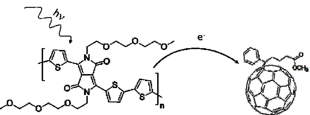
the charge separation and to ensure the migration to the electrodes without recombination. The blending of polymers with different conjugated systems (i.e. electron acceptors, such as fullerene C60), is a very efficient method to achieve the separation of excitons into free carriers, through a photo-induced electron transfer from the polymer to the fullerene (figure 3.1).
Figure 3.1: Photo-induced electron transfer from organic polymer to fullerene.
The charge transfer from the excited state of the polymer towards the
LUMO of an acceptor material, which is located at a lower energy level, is
thermodynamically favorable6. In figure 3.2, it is reported a scheme for the
Figure 3.2: Schematization of the photo-induced charge separation between
donor and acceptor.
The best performance for an organic solar cell is obtained through the so-called bulk heterojunction (BHJ): two different materials are used as carriers of holes and electrons, as well as different doping of silicon that generate the p-n junctions, which are the basis of the inorganic photovoltaic systems. Double-layer devices (donor-acceptor) can therefore be used as classic p-n junctions.3
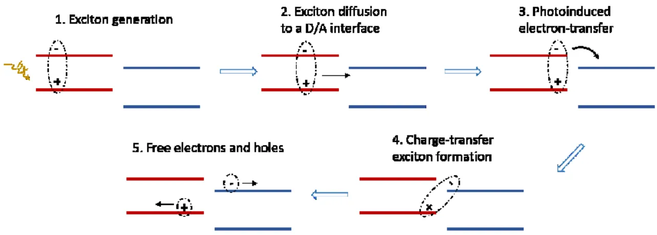
The following steps describe the process of conversion of light into electricity via an organic solar cell:
1) absorption of a photon that leads to the formation of an exciton along the polymeric chain, this generate the electron-hole pair;
2) the exciton diffuses along the material until it reaches a region where its dissociation can take place (charge separation): generally the interface between the two materials where the separation of charge is favored;
Introduction
photoactive materials. The maximum of absorption of sunlight is around 700 nm, which correspond at a low band gap of about 1.77 eV, therefore is necessary to design polymers that adsorbed in the red and near-infrared ranges. To date, the better strategy to model the polymers Eg, is the alternation of a conjugated electron-rich donor (D) unit and a conjugated electron-deficient acceptor (A) unit in the same backbone.8,9
In order to avoid a rapid decay (radiatively or non-radiatively), the exciton must be formed at a distance, from the interface, lower its diffusion length (typically 5-14 nm).10,11 Therefore, the ideal situation occurs when the
donor and acceptor phases form a bicontinuous interpenetrating network at nanometer level. This is the case of the BHJ, which exhibits a separation of the donor-acceptor phases ranging between 10 and 20 nm (figure 3.3). In this network, each interface is at a distance, from the site of absorption, lower than the length of exciton diffusion. In this way, it is also considerably increased the interfacial area between the donor and acceptor phases which results in higher efficiencies of the solar cells. The BHJ may be obtained by deposition of donor-acceptor mixtures from solution.12
The poly(p-phenylenevinylene) (PPV), polythiophenes (PT) and polyfluorene (PFO) are among the materials commonly used in organic photovoltaics. We can also mention the poly [2-methoxy-5-(3′,7′-dimethyloctyloxy)-1,4-phenylenevinylene] (MDMO-PPV) and the poly (3-hexylthiophene) (P3HT) (figure 3.4).
The Buckminster fullerene (C60),13 has the LUMO orbital energetically close
to the work function of the cathode (aluminum coated with LiF or calcium). Given the limited solubility of C60, Wudl synthesized a soluble derivative of the C60, the 1-(3-methoxycarbonyl) propyl-1-phenyl [6,6] C61 (PC60BM)6 (figure 3.4), which is widely used as acceptor in the solar cell polymer/fullerene. For its structural symmetry, the PCBM, has an insufficient absorption in the visible region so this determined a low efficiency of BHJ devices, but the situation can be further improved by replacing acceptor C60 PCBM with its higher fullerene analogue C70 PCBM (PC71BM), which has lower symmetry and allows more transitions.14,15
Introduction
3.1 Architecture of organic photovoltaic devices
The techniques of deposition from solution are the methods of preparation of thin films most commonly used in the production of BHJ solar cells. In fact, the polymers should decompose if subjected to excessive heat and have molar masses too large to be evaporated under vacuum. The most commonly used techniques are the methods of spin-coating, doctor blading and screen-printing. This is a significant point in favor of fabrication of such devices, given that the techniques adopted are simple to realize and low cost.
The general structure used for organic solar cells is similar to that of the organic light emitting diodes (OLED). The devices are manufactured by means of a sandwich geometry.
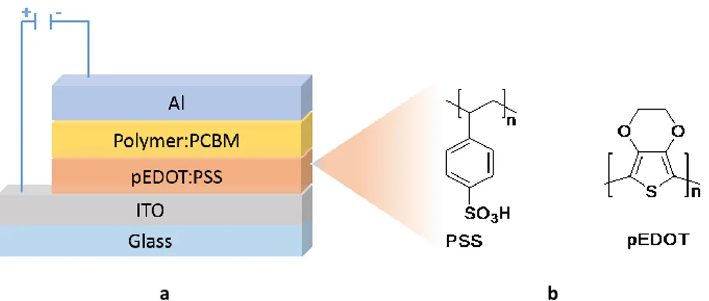
Figure 3.5a shows a schematic representation of a solar cell. The substrates used are transparent and conductor electrodes, such as glass or plastic coated with ITO.
The electrodes in ITO are transparent, conductor but expensive. The support of ITO can be previously structured by means of chemical etching. The support is then coated with PEDOT:PSS; (poly(EDOT) doped with, a polystyrene sulfonate (PSS).
a b
Figure 3.5: a) Scheme of a bulk heterojunction solar cell in the sandwich geometry; b)
chemical structure of PEDOT (poly (3,4-ethylenedioxythiophene)) and PSS (polystyrene sulfonate).
This layer improves the surface quality of the electrode of ITO (reducing the probability of short circuits) and facilitates the extraction of holes. Deposition of the active layer is made using solution techniques, as mentioned above. In the case of small molecules, it is also possible to use the evaporation under high vacuum. Finally, the top metal electrode is evaporated thermally on the active layer under high vacuum (typically 10-7
-10-6 mbar).
To evaluate experimentally the efficiency of a solar cell a series of electrical measurements are carried out on the device, in order to draw a diagram of density current/voltage (J/V) in different experimental conditions. Figure 3.6 shows the J/V characteristics related to a generic photovoltaic cell in dark or under illumination.
Introduction
Figure 3.6: Characteristic curve current-voltage of a solar cell.
The efficiency of the cell is determined by the ratio between the maximum power delivered by the device and the incoming power Pin:
in oc sc in mp mp in out P V J FF P V J P P
In this expression the output power (Pout=Jmp·Vmp) is estimated by evaluating the point of the curve where the product of the current density for the voltage is maximum (area red). While the fill factor (FF) represents the ratio between the maximum measured power Pout and the maximum
theoretical Pth=Jsc·Voc (ratio of the area of the blue rectangle and red rectangle in figure 3.6).
4. Demand of alternative materials in transistors
production
In the last decades, the increasing demand of high-performance electronic devices, bearing unexpected and sophisticated characteristics, such as flexibility and lightness, has pushed the development of new technologies enabling the fabrication of electronic components with such particular features. The transistor is a landmark in the development of modern electronics, and is the key enabling technology in virtually every electronic device today. In a field-effect transistor (FET), the current flowing between two terminals, the so called source and drain electrodes, is amplified by a third electrode, the gate.
During the years, silicon transistors have shown high charge-carrier mobilities and their sizes have progressively been reduced according to the well-known Moore’s law16. However, further improvements could soon be
hampered by the increasing sophistication of the miniaturization process17.
Therefore, to satisfy the increasing requests of the electronics market, the introduction of new materials, such as organic semiconductors, showing good performances but also additional advantages, can be a possible alternative.
With respect to silicon, organic semiconductors can be easily processed from solution on flexible substrate,18 opening new paths to a vast array of
Introduction
because of they can be processed from solution using printing, ink-jet or roll-to-roll techniques, and the high scalability on large area deposition.22,23
4.1 Organic field effect transistors
Organic donor-acceptor polymers exhibit excellent properties in charge-carriers transport within organic field effect transistors24,25 and their high
mobility can be attributed to the particular architecture and to the strong interactions between the polymeric chains, in fact the reduction of the intermolecular distance increase the charge transport.26
The field effect is a phenomenon in which the conductivity of a semiconductor changes due to the application of an electric field.
Figure 4.1: Schematic view of an organic field effect transistor.
Figure 4.1 shows a generic top gate structure, in which source and drain electrodes are deposited on glass (or on flexible) substrate, the organic semiconductor layer is deposited on top and it is separated from the gate by the insulating.
is applied between the source and the drain electrodes (VD), a current (ID)
will flow between these two contacts. The ID is modulated by the applied
gate.
Figure 4.2: Typical current-voltage behavior
The curves reported in figure 4.2, show the typical ID behavior of an OFET,
output drain current increases as the VD increases, until the saturation point
that depends on the applied VG.
The main features that characterize an OFET are the field-effect mobility and the ION/IOFF ratio, the mobility is function of the semiconductor
properties, while the ION/IOFF ratio is the ratio between the saturation value
Introduction
5. Compounds with diketopyrrolopyrrole structure
Donald Farnum and his collaborators at the University of Michigan, in the United States of America, accidentally synthesized the first compound with diketopyrrolopyrrole structure (DPP) in 1974. They reacted ethyl bromoacetate with benzonitrile in the presence of zinc, in the Reformatsky conditions, with the intention of synthesizing the β unsaturated lactam 1, instead the product 2 was obtained, although in a very modest yield (scheme 5.1). For the properties exhibited by the compound 2, such as the bright red colour and low solubility, it was thought that this could be a new organic pigment.27
Scheme 5.1: Synthesis of the DPP.
Currently, the compounds in DPP structure are synthesized through a condensation reaction between an aromatic nitrile and the succinic ester (scheme 5.2).
Scheme 5.2: Succinic method for the synthesis of DPP.
This method allows the synthesis of pigments in which the DPP unit is conjugated to different aromatic groups (i.e., phenyl, thienyl, furyl) in good yields. Furthermore, these derivatives may undergo various synthetic modifications that allow modulating the properties. For example, the alkylation of the lactam units allows increasing the solubility in organic solvents, while by means of electrophilic aromatic substitution reactions it is possible to functionalize the aryl unit. A frequent functionalization is represented by halogenation, which allows obtaining useful intermediates in the synthesis of molecules to more complex structures.28
Compounds containing the DPP units are widely used as industrial pigments for paints, inks, varnishes and plastics due to their exceptional photochemical, thermal and mechanical stability. In recent years, the derivatives with DPP structure have attracted great attention for their applications in organic electronic. In fact, the DPP unit works as an excellent electron-acceptor unit in copolymers with low bandgap used as semiconductors both in solar cells and in organic transistors.29,30
Introduction
absorption maxima and favours the π-π stacking, which in turn, influences the charge transport abilities.
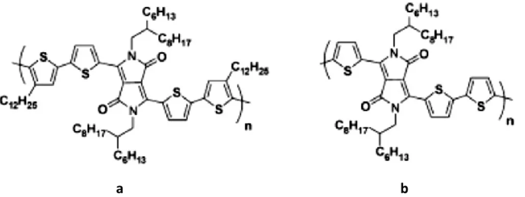
Many polymers and small molecules, containing the unit dithienyl DPP, were incorporated as donors in organic solar cells, having high efficiency. Efficiencies up to 8% were reported by Jannsen31 for solar cells containing
a terpolymer (figure 5.1, a) as donor and the PC71BM as acceptor, and by
Hwang32 for solar cells containing the polymer (figure 5.1, b) in which the
dithienyl DPP unit is alternated with triisopropyl silil
etinil-benzodithiophene.
a b
Figure 5.1: Examples of polymer with TDPP structure in OPV cells.
Winnewisser33 reported a polymer with dithienyl DPP unit (figure 5.2, a) for
application in field-effect transistor that shows ambipolar charge transport properties, reaching ∼0.1 cm2 V-1s-1and ∼0.09 cm2 V-1s-1 for holes and
electrons, respectively. Similar copolymer possessing dithienyl DPP unit (figure 5.2, b) was reported by Janssen34 exhibiting ambipolar transport
a b
Figure 5.2: Examples of polymer with TDPP structure in OFET.
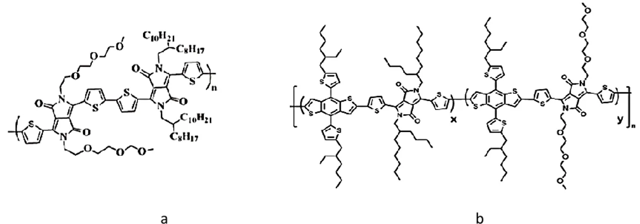
Most applied compounds in organic electronics, which possess the DPP moiety, contain alkyl substituents on the lactam units. The introduction of such group not only increases the solubility in organic solvents but also allows the modulation of the optoelectronic properties. Recent literature reports on examples of dithienyl DPP derivatives containing hydrophilic polyether chains, able of the self-assembly in the solid state.35 For example,
Patil36,37 reported a copolymer in which the alkylated dithienyl DPP units
are alternated to dithienyl DPP units functionalized with triethylen glycol chains (polymer a, Figure 4.5) for applications in transistor with high mobility (electron mobility up to 3 cm2V-1s-1 ). Yang38 showed that the strong
effect exerted by triethylen glycol chains in the self-assembling improves the efficiency of polymer systems (efficiencies from 6.2% to 7.0% with triethylen glycol modification, polymer b, figure 5.3).
Introduction
a b
Figure 5.3: Examples of materials with TDPP structure functionalized
with hydrophilic chains.
Finally, in the last years several jobs in the literature describe the use of DPP derivatives as fluorescent probes for the detection of different analytes, such as, anions (F-, CN-), cations (Zn2+, Hg2+, Cu2+), ROS (H
2O2, ·OH, -OCl) and
thiols.28,39 The interest is justified by the fact that, compared to other
classes of compounds, they have high absorption and high quantum yields of fluorescence together to high thermal and light stability. The revelation comes from changes in the photophysical properties of the probes, indicated by an increase or quenching of fluorescence, together with a red or blue shift in the absorption or emission band. The high fluorescence quantum yields have also allowed the use of DPP derivatives in bioimaging techniques.
Results and discussion
6. New triazole-diketopyrrolopyrrole derivatives with
tunable solubility
One of the critical aspects in the production of organic photovoltaic cells is the use of toxic and pollutant solvents. The introduction of polyethylenglycolic chains can improve the solubility in environmentally friendly solvent, the self-assembly of the BHJ and therefore the charge transfert.36,38
To date, the reverse phase photovoltaic cell proposed by Krebs,40 which is
fully processed by hydroalcoholic mixture, represents the state of the art. The active layer was formed by a fullerene derivative, functionalized with a triethyleneglycol chain (acceptor), and a polythiophene with removable hydrophilic chains (donor). After the deposition from hydroalcoholic solvents, the active layer was heated at about 300°C to remove the hydrophilic chains present on the polymer, generating a film insoluble in water, upon which it is possible to deposit the following layer (scheme 6.1). Although the efficiency of the cell obtained is modest (PCE = 0.7%), the result is interesting because it represents a first step towards the realization of sustainable organic solar cells.
In the scheme 6.1 are reported the structures of organic materials used in the solar cell.
1 P3CT PT-Insoluble
Scheme 6.1: Structures of organic materials used in the cell proposed by Krebs.
My work was aimed at the design and synthesis of new systems with tunable solubility. DPP was used as the central core and the solubility of the final compounds will be modulated both by the introduction of different side chains on the N atoms of the lactam ring and by conjugation of some 1,2,3-triazole moieties at the central core.
The connection of the triazole units was carried out through a cycloaddition reaction that is an interesting example of “click chemistry”. The reaction takes place between 1,3-dipolar azides and alkynes in presence of a copper catalyst, it is regioselective and shows good reproducibility. Using different organic azides we aim to modulate the solubility of the molecules.41
Results and discussion
6.1 Synthesis of small molecules
Scheme 6.2: Synthetic route to compounds 4a-c.
The precursors 1a-c are treated with N-bromosuccinimide to obtain the brominated derivatives; these undergo to silylation, through reaction with trimethylsilylacetylene in presence of Pd(PPh3)4, CuI and trimethylamine, to
give the intermediates 3a-c. The protecting silyls groups were removed by reaction with potassium fluoride to provide the alkynes 4a-c. They contain solubilizing groups with different properties on the lactam rings of DPP core, namely the hydrophobic 2-ethylhexyl chains for 4a or the hydrophilic 2-(2-(2-methoxethoxy)ethoxy)ethyl chains for 4b and t-BOC groups for 4c, respectively.
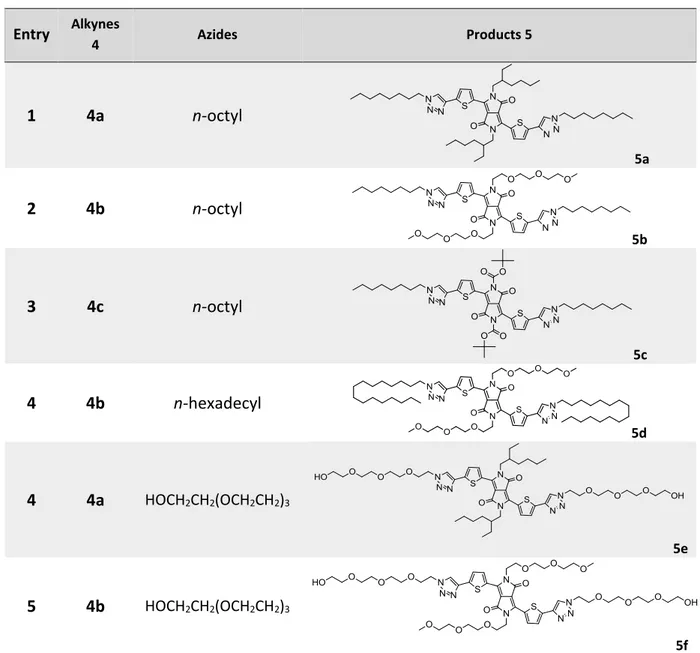
Finally, the compounds 4a-c have been reacted with organic azides in presence of Cu(OAc)2.H2O, in water, to introduce various substituents in the
terminal position of the conjugated backbone. The molecular structures of the obtained small molecules are reported in table 6.1.
Table 6.1:. Structures of compounds 5a-f.
Entry Alkynes 4 Azides Products 5 1 4a n-octyl 5a 2 4b n-octyl 5b 3 4c n-octyl 5c 4 4b n-hexadecyl 5d 4 4a HOCH2CH2(OCH2CH2)3 5e 5 4b HOCH2CH2(OCH2CH2)3
Results and discussion
6.2 Solubility of the small molecules
The solubility of the synthetized compounds was qualitatively tested in solvents with different polarities. The tests were carried out mixing 1mg of each molecules with 0.5 ml of solvent at room temperature and if the solubilization was not complete the mixture was heated. In table 6.2 are reported the results.
Table 6.2: Solubility of compounds 5a-f in solvents of different polarity.
Solvent 5a 5b 5c 5d 5e 5f n-Hexane - - - - Toluene + ++ ++ ++ ++ ± o-Dichlorobenzene ++ ++ ++ ++ ++ ++ CH2Cl2 ++ ++ ++ ++ ++ ++ CHCl3 ++ ++ ++ ++ ++ ++ THF ++ ++ ++ ++ ++ ++ Isopropanol - ++ + + + + Ethanol - ++ + + + ++ Acetone + ++ ++ ++ ++ ++ Methanol - ++ + ± + ++ H2O - - - ++
++ soluble at room temperature; + soluble on heating; ± partly soluble; - insoluble.
All compounds are insoluble in hexane but they are soluble in halogenated solvent as o-dichlorobenzene, dichloromethane and chloroform, as well as in tetrahydrofuran, in acetone and in toluene (only the 5f, is partly soluble
Additionally their solubility in alcohols increases as the number of hydrophilic oligoether chains increase. Compound 5f, possessing oligoether chains on both the DPP core and the triazole units, is soluble in water at room temperature. Singularly, only few water-soluble DPP derivatives have been reported so far.42,43,44
6.3 UV-Vis characterization in solution and in the solid
state
The molecules were characterized through UV-Vis spectroscopy; the absorption and emission spectra are recorded in chloroform (see figure 6.1).
Results and discussion
Figure 6.1: Normalized UV-Vis absorption (blue line) and emission (red line) spectra of
compounds (a) 5a, (b) 5b, (c) 5c, (d) 5d, (e) 5e, and (f) 5f in solution (CHCl3, 10–5 M).
All compounds exhibit similar absorption and emission maximum with the exception of 5c that shows a blue shift of about 50 nm, probably due to the higher steric hindrance of the t-BOC groups on the DPP core, which reduces the planarity/conjugation of the molecules. The higher planarity of compounds 5a, 5b, and 5d–f with respect to compound 5c allowed us to visualize resolved vibronic structure.
Furthermore molar extinction coefficients (ε) have been calculated and all molecules manifest similar and high values ranging from 3.39 × 10⁴ to 5.36
× 104 M–1 cm–1.
Table 6.3: Optical data of the compounds 5a-f in chloroform solution. Compound λmax abs
(nm)[a] (M-1ε cm-1) λ(nm)max PLem[a] (nm)λonset [a]
5a 592 5.36x10⁴ 616 620 5b 586 4.19x10⁴ 610 618 5c 535 4.16x10⁴ 600 610 5d 586 3.30x10⁴ 610 616 5e 592 3.39x10⁴ 614 625 5f 587 4.43x10⁴ 611 625 [a] 10-5 M CHCl
3 solution. [b] Optical bandgap evaluated as Eg = 1240/λonset.
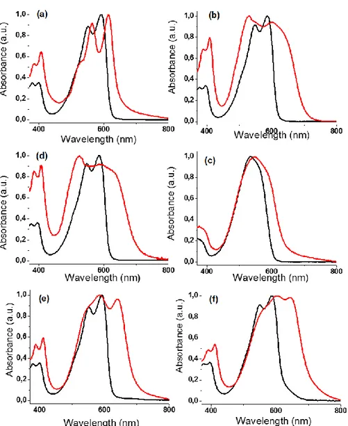
All compounds were also characterized at the solid state, as thin spin-coated films (1000 rpm/60 sec, then 2000 rpm/60 sec) from chloroform solution (10mg/ml), on glass plates. The UV-Vis absorption curves at the solid state, exhibit a broadening of the absorption band and a red shift of the absorption onset when compared to the data acquired in solution. This is a clear indication of an increment of the structural order.
From the absorption spectra, the optical energy gaps in solution and in film have been calculated; all compounds exhibit low values of the optical bandgap at the solid state, as summarized in table 6.4.
Results and discussion
Figure 6.2: Normalized UV-Vis absorption in solution (black line) and UV-Vis absorption
at the solid state (red line) spectra of compounds (a) 5a, (b) 5b, (c) 5c, (d) 5d, (e) 5e, and (f) 5f.
Table 6.4: Optical data of the compounds 5a-f in chloroform solution and in film. Compound (nm)λmax sol[a] λ(nm) onset sol[a] (eV)Egsol[c] (nm) λmax film[b] λ(nm) onset film[b] (eV) Egfilm[c]
5a 592 620 2.00 616 652 1.85 5b 586 618 2.01 529 703 1.76 5c 535 610 2.03 548 644 1.92 5d 586 616 2.01 525 706 1.76 5e 592 625 1.98 586 702 1.77 5f 587 625 1.98 601 715 1.73 [a] 10-5 M CHCl
3 solution. [b] 10mg/ml (1000 rpm/60s) CHCl3 solution [c] Optical bandgap evaluated as Eg = 1240/λonset.
6.4 Determination of HOMO and LUMO levels
Electrochemical properties and HOMO and LUMO levels were estimated through CV, using a platinum working electrode, a platinum counter electrode and an Ag/Ag+ reference electrode. While the
tetrabutylammonium hexafluorophosphate was used as supporting electrolyte and the ferrocene/ferrocenium (Fc/Fc+) redox couple as external
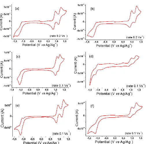
standard. CV curves of all compounds show two reversible oxidation and one irreversible reduction waves (figure 6.3).
Results and discussion
Figure 6.3: Cyclic voltammograms on a Pt working electrode in 0.1M n-Bu4NPF6/ anhydrous dichloromethane at room temperature for compounds 5a (a), 5b (b), 5c (c),
5d (d), 5e (e) and 5f (f).
The HOMO energy levels were estimated, for each molecule, according to the empirical equation: HOMO = - (Eox + 5.1V), where Eox is the onset of the
first peak potential versus Fc/Fc+ reference and -5.1eV is the position of the
formal potential of the Fc/Fc+ redox couple in the Fermi scale.45 While the
LUMO energy levels were calculated as follows: LUMO = HOMO + Egopt. The
electrochemical data of compounds 5a-f in CH2Cl2 solution are reported in
Table 6.5: Electrochemical data of the compounds 5a-f in dichloromethane solution
Compound Eox (V) Ered (V) HOMO (eV) LUMO (eV)
5a 0.38 -1.78 -5.48 -3.48 5b 0.41 -1.74 -5.51 -3.50 5c 0.55 -1.52 -5.65 -3.62 5d 0.42 -1.69 -5.52 -3.51 5e 0.37 -1.67 -5.47 -3.49 5f 0.41 -1.65 -5.51 -3.53
Compounds 5a-b, d-f possessing alkyl and/or oligoether chains show similar electrochemical properties, suggesting that the variations in the side-chains do not cause any noticeable difference of electronic behavior. For all these molecules, the HOMO and LUMO levels are approximately the same ranging from -5.5 and -3.5, respectively. Otherwise, the introduction of the more electronegative t-BOC groups on the DPP core produces a small lowering of HOMO-LUMO energy levels of compound 5c.
6.5 Preliminary tests in solar cells
All small molecules were tested in BHJ solar cells, using they as donor (D) materials and [6,6]-Phenyl-C61-butyric acid methyl ester (PC60BM) as
acceptor (A) material. The cells were fabricated using small
Results and discussion
(100nm). The architecture used in fabrication of solar cells is schematized in figure 6.4:
Figure 6.4: The architecture used for solar cell device.
The active layer was spin coated from chloroform solution, at two different rates, at 500 or 1000 rpm, and then annealed on hotplate at 130°C under inert atmosphere for 10 min.
In table 6.6 are reported the performance data of the cells prepared with different spinning rate for the molecule 5a.
Table 6.6: Photovoltaic parameters for ITO/PEDOT:PSS/5a:PC60BM/Ca/Al solar cells under AM1.5G, 1000 W/m2 illumination.
Devices rpm Jsc (mA/cm2) Voc (V) FF (%) PCE (%)
5a/PC60BM 500 -0.544±0.020 0.571±0.021 20.01±0.32 -
a peak at 520 nm. For comparison, the absorption spectrum of the solar cell device was also recorded (figure 6.7).
Figure 6.5: J-V characteristics of 5a/PC60BM based solar cell device in the dark (black line) and under AM1.5G, 1000 W/m2 illumination (500 rpm in red line and 1000 rpm in
Results and discussion
Figure 6.7: Absorption spectrum of the ITO/PEDOT:PSS/5a:PC60BM/Ca/Al solar cell (500 rpm in black line and 1000 rpm in red line).
The investigated systems show very low values of FF, Jsc and PCE, but the
VOC is considerably high. Comparing the EQE and the absorbance spectrum
of the solar cell, is evident that the charge generation is rather balanced between the fullerene than the molecule. Probably the reason of these poor results could be attributed to the low conjugation of the backbone.
7. New conjugated polymers for bulk heterojunction solar
cells
In view of the results obtained with the small molecules I focused my attention on the synthesis of different polymers functionalized with hydrophilic groups. The polymers possess a DPP core-unit functionalized whit triethyleneglycol chains, with the aim of improving the solubility of the polymers in polar solvents.
and a vinyl (TegDPPV), a thiophene ring (TegDPPT) or a (ethylhexyloxy) benzodithiophene group, (TegDPPBDT) were synthetized through the efficient Stille cross coupling involving Pd(PPh3)4 as catalyst, and purified by
Soxhlet extraction. Furthermore the molecular weight of the polymers was estimated through GPC analysis while the optical and the electrochemical properties were investigated by UV-Vis spectroscopy and CV, respectively.46
Scheme 7.1: Synthesis of TegDPPV, TegDPPT and TegDPPBDT.
Solubility tests show that synthetized polymers are soluble only in halogenated solvents, in order to improve the solubility of my systems in polar solvent, TegDPP units was linked to a thiophene unit, functionalized
Results and discussion
weight, UV-Vis spectroscopy to analyze the optical properties and CV to investigate HOMO and LUMO energy levels.
1 3 5 TegDPPTegES.
Scheme 7.2: Synthesis of TegDPPTegES.
Also, the polymer TegDPPTegES is soluble only in halogenated solvents and to obtain new polymers soluble in polar solvents, the synthesis of TegDPPK was designed, in addition, this polymer shows a side chain removable by thermal treatment, to modulate the solubility. To synthetize the polymer I used the Stille reaction and it was isolated by Soxhlet extraction, also this polymer was characterized through GPC, UV-Vis and CV.
Considering that TegDPPK is not soluble in polar solvents, in order to simplify the polymeric structure, TegDPPK1 was synthesized, which shares some similarities with TegDPPK, but I realized the direct connection between TegDPP unit and the thiophene functionalized with the ester group. Furthermore to obtain the polymer a different synthetic procedure was employed: the Direct Heteroarylation Polymerization (DAHP).47,48,49
With this procedure, it is not necessary to synthesize any stannylated reagent, but I took advantage of the reaction between the halogenated thiophene derivate and the TegDPP monomer. Also this polymer was purified through Soxhlet extraction and characterized by GPC, UV-Vis and CV to investigate the molecular weight, the optical and the electrochemical properties, respectively.
1 6 TegDPPK1
Scheme 7.4: Synthesis of TegDPPK1.
Results and discussion
7.1 GPC characterization of the polymers
The polymers were analyzed by GPC in order to determine the molecular weight and the polydispersity. The analyses were carried out using the polystyrene as standard and a mixture of chloroform and DMF (1:0.2 v/v) as eluent to facilitate the elution of the polymers. It was not possible to use pure chloroform because the polymers were not eluted, reasonable due to establishing strong interactions with the stationary phase. For polymers
TegDPPTegES and TegDPPV, the GPC analysis showed the presence of
polymeric and oligomeric species with molecular weights (Mn) markedly
different. TegDPPT, TegDPPBDT, TegDPPK and TegDPPK1 have similar molecular weight and a polydispersity index (PDI) ranging from 1.6 and 3.2 as reported in table 7.1.
Table 7.1: GPC data for DPP-based polymers.
Polymer Mn (kDa) Mw (kDa) PDI
TegDPPTV[a] 20.3/1.1 29.4/1.3 1.4/1.2 TegDPPT 16.1 25.4 1.6 TegDPPBDT 18.5 42.9 2.3 TegDPPTegES[a] 21.5/1.2 28.4/1.8 1.3/1.5 TegDPPK 13 41.3 3.2 TegDPPK1 14.7 31.3 2.1
7.2 UV-Vis characterization of the polymers
All polymers were characterized through UV-Vis analysis; the spectra were registered both in chloroform solution and in the solid state. For each polymer, the optical energy gap was calculated in solution and in film. The calculation takes account of the absorption onset in the UV-Vis spectra using the eq4uation:
Eg = 1240/λonset
Polymers TegDPPV, TegDPPBDT, TegDPPTegES, TegDPPK and TegDPPK1 were solubilized in chloroform and then spin-coated (1000 rpm/60 sec, then 2000 rpm/60 sec) films, on glass plates, while for TegDPPT, it was not possible to obtain the film due to wettability problems. The overlapping of the normalized spectra in solution and in films for all polymers, were reported in figure 7.1 with exception of TegDPPT for which it is available only the spectrum in solution.
The polymers TegDPPV, TegDPPBDT and, especially, TegDPPK1, show a red shift of the absorption onset in the solid state: that is a clear indication of an increment of the structural order.
Results and discussion
Figure 7.1: UV-Vis normalized spectra of TegDPPV (a), TegDPPT (b), TegDPPBDT (c), TegDPPTegES (d), TegDPPK (e), and TegDPPK1 (f) in CHCl3 solution
Table 7.2: Optic properties of the synthesized polymers.
Polymers λmax sol (nm)[a] λonset sol (nm) [a] λmax film (nm) [b] λonset film (nm) [b] Eg opt (eV) [c] TegDPPV 756 935 777[d] 1053 1.19
TegDPPT 869 1000 -[e] -[e] -[e]
TegDPPBDT 743 900 765[f] 971 1.28
TegDPPTegES 758 941 760[g] 982 1.27
TegDPPK 771 912 777[h] 975 1.27
TegDPPK1 651 880 741[i] 918 1.35
[a] Measured in dilute CHCl3 solution. [b] Films deposited by spin-coating from CHCl3 solution. [c] Optical band-gap evaluated as Eg = 1240/λonset film. [d] Film from CHCl3 solution (10 mg/ml). [e] For TegDPPT it was not possible to acquire the UV/Vis/NIR spectrum in the solid state due to its poor wettability. [f] Film from CHCl3 solution (6 mg/ml). [g] Film from CHCl3 solution (5 mg/ml). [h] Film from CHCl3 solution (3.5 mg/ml). [i] Film from CHCl3 solution (5 mg/ml).
The optical band-gaps (Egopt) of the polymers in the solid state was
estimated from the onset of the thin-film absorptions, (Table 7.2). Low optical band-gaps, ranging from 1.19 to 1.28, were calculated for TegDPPV
TegDPPBDT, TegDPPTegES and TegDPPK. The polymer TegDPPK1 is
characterized by a larger Egopt if compared to TegDPPK, due to the smaller
network of polythiophene donor blocks.
7.3 Thermal treatment of polymers TegDPPK and
TegDPPK1
Results and discussion
hotplate at 300°C in air for 2 minutes. IR spectra show a decrease of the band at about 1700 cm-1 related to the carboxylic group stretching (Figure
7.2), suggesting their decomposition.
Figure 7.2: FT-IR spectra of TegDPPK (a) and TegDPPK1 (b) before (black) and after
(red) thermal cleavage at 300 °C for 2 min.
The cleavage causes a drastic reduction of solubility in chloroform improving the resistance of polymers to solvent attack leading, consequently, to morphologically stable films. Furthermore, the removal of the side chains, increase the charge transport properties of the polymers.50
Thermal gravimetric analyses (TGA) confirm the thermal cleavage of the side chains. Thermograms curves in figure 7.3 shows a loss in weight of 25 % and 28 % for TegDPPK and TegDPPK1, respectively, ranging from 220 and 400 °C due to the thermolysis of the ester side chains.
Figure 7.3: TGA analysis of TegDPPK in air (a) and under nitrogen (c); TGA analysis of TegDPPK1 in air (b) and under nitrogen (d).
Furthermore, after thermal treatment, the UV-Vis spectra show absorption profiles very similar to the initial polymers, as reported in figure 7.4.
Results and discussion
7.4 Determination of HOMO and LUMO levels of the
polymers
Electrochemical properties of the polymers were investigated through cyclic voltammetry (CV). The CV curves (figure 7.5) were obtained after the deposition of a thin film on the platinum working electrode in 0.1 M tetrabutylammonium hexafluorophosphate (nBu4NPF6)/acetonitrile
solution. The Fc/Fc+ redox couple was used as an external standard to
calibrate all the measurements. The HOMO and LUMO energy levels were calculated employing the following empirical equations:
EHOMO = – (Eox + 5.1 V) and ELUMO = – (Ered + 5.1 V)
where Eox and Ered are the onset oxidation and reduction potentials vs
Fc/Fc+, respectively, while -5.1 eV is the position of the formal potential of
the Fc/Fc+ redox couple on the Fermi scale.45
The electrochemical data reported in table 7.3, shows values of electrochemical band gaps larger than the optical ones. The reason of this phenomenon is probably due at the presence of an energy barrier at the interface between the working electrode surface and the polymeric film.51
The current intensity for the reduction curves is lower than that of oxidation ones, therefore the synthetized polymers are good holes transporters, but they are not good transporters of electrons. The same observations have
Figure 7.5: Cyclic voltammograms of TegDPPV (a), TegDPPT (b), TegDPPBDT (c), TegDPPTegES (d), TegDPPK (e) and TegDPPK1 (f) films on a Pt working electrode in 0.1
Results and discussion
Table 7.3: Electrochemical data of TegDPP-based polymers.
Polymer Eox (V) [a] HOMO
(eV)[b] Ered (V)[a]
LUMO (eV)[b] Egel (eV)[c] TegDPPV 0.30 –5.40 –1.25 –3.85 1.55 TegDPPT 0.06 –5.16 –1.31 –3.79 1.37 TegDPPBDT 0.25 –5.35 –1.38 –3.72 1.63 TegDPPTegES 0.12 –5.22 –1.38 –3.72 1.50 TegDPPK 0.25 –5.35 –1.51 –3.59 1.76 TegDPPK1 0.40 –5.50 1.35 –3.75 1.75
[a] Onset oxidation and reduction potentials vs Fc/Fc+. [b] HOMO–LUMO energy levels evaluated as EHOMO = –(Eoxonset + 5.1 V) and ELUMO = –(Eredonset + 5.1 V) where Eonset is measured vs Fc/Fc+ reference, and –5.1 eV is the position of the formal potential of the Fc/Fc+ redox couple on the Fermi scale.45 [c] Electrochemical band-gap calculated from Eg = –(Eox – Ered).
7.5 Tests in BHJ solar cells
All polymers were tested in BHJ solar cells, using them as donor (D) materials and [6,6]-Phenyl-C71-butyric acid methyl ester (PC70BM) as
acceptor (A) material.
The cells were prepared using the direct configuration: ITO/PEDOT-PSS/Polymer:PC70BM/Ca/Al. The composition of the active layer is D/A 1:2
(wt/wt) and after the deposition, from ortho-dichlorobenzene solution, it undergoes to thermal annealing (testing the treatment at both 150 and 290°C) under inert atmosphere for 2 minutes.
figure 7.6) was used, and the active layer composed by D/A in ratio 1:2 (wt/wt), was annealed at 290°C under inert atmosphere for 2 minutes (see table 7.4). All polymers exhibit very poor photovoltaic parameters with exception for TegDPPBDT that exhibits the most promising results and for which I report the obtained values.
Figure 7.6: The architecture used for solar cell device.
In table 7.4 are reported the photovoltaic values both for the average and the best cell in the reverse phase.
Table 7.4: PV parameters for ITO/ZnO/TegDPPBDT:PC70BM/MoO3/Ag solar cells under AM1.5G, 1000 W/m2 illumination.
Device Jsc (mA/cm2)] Voc (V) FF (%) PCE (%)
Average 5.45 ± 0.30 0.598 ± 0.01 41.1 ± 3.1 1.34 ± 0.18
Results and discussion
2.36 mA/cm2, V
oc = 0.523 V, FF = 42.9 %, efficiency = 0.53 %) were less
satisfactory.
The I/V curves under dark conditions and under illumination (AM1.5G, 1000 W/m2) are shown in figure 6.7 for the best performing device. The external
quantum efficiency curve (EQE) of the solar cell was also reported and it shows a broad spectrum in the visible and NIR region with a peak at 520 nm (figure 7.8). For comparison, the absorption spectrum of the solar cell device was also recorded (figure 7.9).
Figure 7.7: J–V characteristics of a TegDPPBDT:PC70BM-based inverted solar cell device in the dark (black open circles) and under AM1.5G, 1000 W/m2 illumination (red solid
Figure 7.8: EQE spectrum of the ITO/ZnO/TegDPPBDT:PC70BM/MoO3/Ag solar cell.
Figure 7.9: Absorption spectrum of the ITO/ZnO/TegDPPBDT:PC70BM/MoO3/Ag solar cell.
Although TegDPPBDT adsorbs very well in the NIR region, the photocurrent in this part of the spectrum is very poor, because most of the charge
Results and discussion
7.6 Tests in organic field-effect transistor
During my visiting period in the Northwestern University, all polymers were tested in a bottom-contact, top-gate field-effect transistor configuration, using the CYTOP, a fluoropolymeric material, as dielectric layer. Gold source and drain contacts are used as the injecting/extracting electrodes, while aluminum is used here as the top gate electrode. The active layer was deposited from chloroform solution and thermally annealed at 150°C on hotplate under inert atmosphere for 15 minutes. Also in this case, the only polymer exhibiting the most promising performances is TegDPPBDT whose performance data, both for the average and for the best device, are summarized in table 7.5.
Figure 7.10: The architecture used for organic field-effect transistor.
Table 7.5: Parameters for top gate OFET.
Device μh (cm2 V-1 s-1) Vth (V) Ion/Ioff
The output curves (figure 7.11) were registered applying different gate voltages, ranging from -20 V to -100 V, while the reported transfer curve (figure 7.12) was registered applying a drain voltage of -80 V.
Figure 7.11: Plot of drain current ID versus drain voltage VD at various gate voltages VG.
Results and discussion
The ID/VG curve shows a hysteresis probably due to the presence of charge
trapping site in the semiconductor material or at the OSC/insulator interface.
8 Synthesis of TegDPPBDT-HMW and EHDPPBDT
One the main features that influences power conversion efficiency in organic solar cells as well as channel currents and field-effect mobilities in OFETs is the molecular weight of the involved polymer, in particular high molecular weight improves the performance of organic devices.53,54
Therefore, in order to increase the performances in organic devices, I repeated the synthesis of TegDPPBDT polymer to obtain a new polymer (TegDPPBDT-HMW) with higher molecular weight. With this aim, a different combination between catalyst and ligand has been used, and in particular Pd2(dba)3 and P(o-tol)3 were employed.
1 4 TegDPPBDT-HMW
hydrophilic and hydrophobic side chains, the know polymer, EHDPPBDT55,56
was synthetized. This last possesses the same backbone of
TegDPPBDT-HMW, but the N atoms of the DPP core has been functionalized with
ethylhexyl chains (EHDPP).
EHDPP 4 EHDPPBDT
Scheme 8.2: Synthesis of EHPPBDT.
Both the polymers were synthetized using the same reaction conditions and purified by Soxhlet extraction with methanol, acetone, hexane and chloroform. The two polymers have been obtained in good yield.
8.1 GPC characterization of the polymers
The molecular weight of the polymers was estimated through GPC analysis carried out at 150°C, using trichlorobenzene as eluent and polystyrene as standard. Both the polymers exhibit high molecular weight ranging from 77.3 and 68.7 (KDa) as reported in table 8.1, furthermore
TegDPPBDT-Results and discussion
Table 8.1: GPC data.
Polymer Mn (kDa) Mw (kDa) PDI
TegDPPBDT-HMW 77.3 278.3 3.6
EHDPPBDT 68.7 158.0 2.3
8.2 UV-Vis characterization in solution and in the solid
state
The two polymers were characterized through UV-Vis spectroscopy both in chloroform solution and at the solid state as thin spin-coated films (1000 rpm/60 sec) from chloroform solution (6mg/ml).
Figure 8.1: UV-Vis normalized spectra of TegDPPBDT-HMW (a) and EHDPPBDT (b) in
CHCl3 solution (black line) and in film (red line).
The UV-Vis absorption curves, for both polymers in thin films, exhibited a slight broadening of the absorption band and a red shift of the absorption
Table 8.2: Optic properties of the synthesized polymers.
Polymers λmax sol (nm)[a] λonset sol (nm) [a] λmax film (nm) [b] λonset film (nm) [b] Eg opt (eV) [c] TegDPPBDT-HMW 745 869 752 913 1.35 EHDPPBDT 747 901 747 929 1.33
[a] Measured in dilute CHCl3 solution. [b] Films deposited by spin-coating from CHCl3 solution. [c] Optical band-gap evaluated as Eg = 1240/λonset film.
From the onset values, at the solid state for TegDPPBDT-HMW and
EHDPPBDT, the optical bandgaps were calculated to be 1.35 and 1.33 eV,
respectively.
Figure 8.2: UV-Vis normalized spectra of TegDPPBDT-HMW (black line), EHDPPBDT
(red line) and TegDPPBDT (blue line) as film.
Comparing UV-Vis spectra, at the solid state, of TegDPPBDT-HMW and
Results and discussion
a decrease of the planar conformation and a reduction of the effective conjugation length, involving a worse molecular packing.56,38
This phenomenon caused also a slight increment of the optical energy gap from 1.28 eV for TegDPPBDT to 1.35 and 1.33 eV for TegDPPBDT-HMW and
EHDPPBDT, respectively.
8.3 Determination of HOMO and LUMO levels
Electrochemical properties of the polymers were investigated through cyclic voltammetry, using a platinum working electrode, a platinum counter electrode and an Ag/Ag+ reference electrode. Furthermore
tetrabutylammonium hexafluorophosphate was utilized as supporting electrolyte and the ferrocene/ferrocenium (Fc/Fc+) redox couple as external
standard. The CV curves of the polymers are reported in figure 8.1.
Figure 8.4: Cyclic voltammograms of TegDPPBDT-HMW (a), EHDPPTBDT (b) films on a
The HOMO and LUMO energy levels were estimated according to the empirical equations:
HOMO = – (Eox
onset + 5.1V) and LUMO = – (Ered onset + 5.1 V)
where the Eonset is measured vs Fc/Fc+ reference, and –5.1 eV is the position
of the formal potential of the Fc/Fc+ redox couple on the Fermi scale.45
The electrochemical data are summarized in table 8.3.
Table 8.3: Electrochemical data of DPP-based polymers.
Polymer Eox (V) [a] HOMO
(eV) Ered (V) [a] LUMO (eV) Eg el (eV)[b] TegDPPBDT-HMW 0.09 -5.19 -1.45 -3.65 1.54 EHDPPBDT 0.19 -5.29 -1.45 -3.65 1.64
[a] Onset oxidation and reduction potentials vs Fc/Fc+. [b] Electrochemical band-gap calculated from Eg = – (Eox – Ered).
8.4 Tests in organic field-effect transistor
The polymers TegDPPBDT-HMW and EHDPPBDT were tested in a bottom-contact, top-gate field-effect transistor configuration, using the CYTOP or the Poly(methyl methacrylate) (PMMA), as dielectric layer. Gold source and drain contacts are used as the injecting/extracting electrodes, while
Results and discussion
Figure 8.5: The architecture used for organic field-effect transistor.
Regrettably, investigations on devices processed using CYTOP or PMMA, presented poor performance data and in particular very low values of mobility, for which was not possible to register the output curves, for both the polymers.
This experimental evidence confirms, as previously mentioned, that molecular packing could negatively influenced by the high molecular weight of the polymers. Furthermore, it is known that opto-electronic performances can be improved by high molecular weight, but up to a certain range, while elevated molecular weight determined less significant enhancement.57
Conclusions
During my PhD course I focused my attention on the DPP unit used as precursor for the synthesis of several small molecules and different polymers. To modulate the solubility of these compounds I introduced different chains on the N-atom of the lactam ring and in particular I used oligoether, alkyl chains or terz-Boc group.
DPP unit was used in the synthesis of new triazole-diketopyrrolopyrrole derivatives. The fine-tuning of their solubility results from the introduction of different side chains on the N atom of the lactam ring and on the triazole unit conjugated with the DPP central core.
Small molecules exhibit good solubility in common organic solvents and their solubility in alcohols increases as the number of oligoether chains increases. Remarkably, compound 5f, possessing polar side chains both on DPP core and on triazole ring, is soluble also in water at room temperature. Optical and electrochemical properties of the compounds 5a–f were investigated and all molecules show low energy gaps with maximum of absorption in the deep-red region.
Tests of small molecules in BHJ solar cells show that synthetized compounds may not be proficiently used in the fabrication of organic solar cells, probably because the conjugation of the backbone is not adequately extended.
To increase the extension of the conjugated backbone different polymers have been realized. For their synthesis I employed the DPP unit functionalized with triethylene glycol side chains and it was alternated to
synthesized thought the Stille cross-coupling reaction, while to obtain the polymer TegDPPK1 the direct hetero arylation polymerization has been involved. This reaction avoid the employment of stannilated derivatives making it a good candidate for industrial production on large scale.
All polymers were characterized through GPC chromatography, UV-Vis spectroscopy in solution and in film and CV.
All compounds, at the solid state, exhibit absorption peaks at wavelengths larger than 700 nm and low band-gaps. The spectra at the solid state show broader absorption band in the NIR region and shoulder peaks with respect to the corresponding spectra in solution. These effects are more pronounced for TegDPPK1, which exhibits a significant red-shift of the maximum absorption peak.
Films of TegDPPK and TegDPPK1, possessing thermally cleavable side chains, after thermal treatment at 300°C for 2 minutes exhibit resistance to common organic solvents attack.
Tests of the synthetized polymers, in BHJ solar cells, reveal that only
TegDPPBDT can be profitably used as donor material, and at the same way
it is the only material that exhibits interesting performance in OFETs, with hole mobilities around 1̇·10-2 cm2·V-1·s-1.
In order to improve the performances of TegDPPBDT polymer in organic devices, a different synthetic procedure was used to increase the molecular weight obtaining TegDPPBDT-HMW polymer and to study the influence of
Conclusions
than TegDPPBDT, suggesting that use of Pd2(dba)3 as catalyst improves
polymerization reaction of DPP-based polymers.
UV-Vis data of TegDPPBDT-HMW and EHDPPBDT films show a blue shift of the absorption onset and a thinner band with respect to the film obtained from TegDPPBDT. These features suggest that high molecular weight induces a less planar conformation of the polymeric chain determining a worse molecular packing at the solid state. Instead the different alkyl or oligoether side chains, in this case, do not influence the packing.
TegDPPBDT-HMW and EHDPPBDT polymers were also characterized
through CV, exhibiting low values of electrochemical band gaps.
Finally, tests in organic field-effect transistor exhibit low values of charge carrier mobility for the last two synthetized polymers, probably due to a worse molecular packing.
Experimental section
9 Solvents and reagents
The reaction solvents were distilled in nitrogen stream immediately before their use. In particular, the THF and toluene were distilled from sodium-benzophenone and chloroform and methylene chloride with phosphorus pentoxide. The solvents for extraction and chromatography and the commercial reagents were used without further purification. The chromatography was conducted using silica gel Macherey-Nagel (60, Section particles 0.063-0.2 mm), while for the TLC analysis were used sheets of silica gel 60 F254 supported on aluminum (Alugram Sil G / UV254 Macherey-Nagel ).
9.1 Instruments
The spectra 1H-NMR and 13C-NMR were recorded on a Varian Inova 400 and
100.6 MHz respectively; using the peak of the proton of residue in CDCl3 (δ
= 7.24 ppm) as internal standard for 1H spectra, and the signals of the CDCl 3
(δ = 77 ppm) as internal standard for 13C spectra. The IR spectra were
recorded on a Perkin-Elmer FT-IR Spectrum Bx. The UV-Vis absorption measurements were performed on a spectrometer Shimadzu UV-2401PC. TGA analysis were performed in air or under nitrogen using a Perkin–Elmer TGA-7 device. Cyclic voltammetry measurements were carried out with an Autolab potentiostat (model PGSTAT128N) by Metrohm using a conventional three-electrode configuration. Current density–voltage (J–V)
of 1000 W/m2. The EQE measurements were carried out using an IPCE
(Incident Photon-to-current Conversion Efficiency) system (IPCELS200, Dyers) calibrated with an UV-enhanced Si detector (Thorlabs, 250–1100 nm). OFETs measurements were recorded trough an Agilent 4155C semiconductor parameter analyzer.
Experimental section
10 Synthesis of
3,6-Bis(5-bromothiophen-2-yl)-2,5-bis(2-ethylhexyl)pyrrolo-[3,4-c]pyrrole-1,4(2H,5H)-dione
1a 2a
Scheme 10.1: Synthesis of 2a.
Monomer 2a was synthesized according to a modified literature procedure.58 A nitrogen-purged, three-necked, round-bottomed flask
covered with aluminum foil and equipped with a magnetic stirrer was charged under nitrogen with a solution of 1.30 mmol of compound 2,5-bis(2-ethylhexyl)pyrrolo-[3,4-c]pyrrole-1,4(2H,5H)-dione (1a,) in dry chloroform (30ml). N-Bromosuccinimide (2.72 mmol) was added in one portion, and then the mixture was stirred at room temperature in the dark for 24 h. The mixture was poured into methanol (80 ml), and the resulting suspension was stirred at room temperature for 5 min. The solid was then collected by vacuum filtration and washed with several portions of methanol. After drying in vacuum, pure product 2a was obtained as a dark purple solid (0.579 g, 65 %).
1H NMR (400 MHz, CDCl
3): δ = 8.61 (d, J = 4.0 Hz, 2 H), 7.20 (d, J = 4.0 Hz, 2
13C NMR (100.6 MHz, CDCl
3): δ = 161.3, 139.4, 135.4, 131.4, 131.1, 119.0,
107.9, 46.0, 39.1, 30.1, 28.3, 23.5, 23.0, 14.0, 10.4 (one coincident signal not observed) ppm. IR (KBr): ῡ = 3085, 2957, 2926, 2859, 1655, 1556, 1449, 1412, 1399, 1100 cm–1.
10.1 Synthesis of 2,5-bis(2-(2-(2-methoxyethoxy)ethoxy)
ethyl)-3,6-di(thiophen-2-yl)pyrrolo[3,4-c]pyrrole-1,4
(2H,5H)-dione
DPP TegDPPScheme 10.2: Synthesis of the TegDPP.
The alkylation of 3,6-di(thiophen-2-yl)pyrrolo[3,4-c]pyrrole-1,4(2H,5H)-dione (DPP) was carried out according to the literature procedure reported by Patil et al.59 In a 3-neck flask of 50 ml, equipped with a bubble condenser
and magnetic stirrer, were introduced, by operating in a current of nitrogen, the DPP (3.33 mmol), the Bu4NBr (0.33 mmol), and the K2CO3
(16.6 mmol). Then, a solution of tri(ethylene glycol) methyl ether tosylate (19.65 mmol) in DMF (25 mmol) was added.
![Table 6.4: Optical data of the compounds 5a-f in chloroform solution and in film. Compound (nm)λ max sol [a] λ (nm) onset sol [a] (eV)Eg sol [c] (nm) λ max film [b] λ (nm) onset film[b] (eV) Eg film [c]](https://thumb-eu.123doks.com/thumbv2/123dokorg/4480217.32301/38.892.148.787.187.440/table-optical-compounds-chloroform-solution-compound-onset-onset.webp)