Università degli Studi di Salerno
Department of Chemistry and Biology
Ph.D. in Chemistry
Polymeric Aerogels
Tutor : Author: Prof. Gaetano Guerra Dr. Simona Longo
Co- Tutor :
Dr. Christophe Daniel
“[...] La nobiltà dell’uomo, acquisita in cento secoli di prove ed errori, era consistita nel farsi signore della materia, [...] mi ero iscritto a Chimica perché a questa nobiltà mi volevo mantenere fedele, vincere la materia è comprenderla, e comprendere la materia è necessario per comprendere noi stessi [...] "
Index
Introduction 1
References 11
Part I : Physically Crosslinked Polymeric Aerogel
Chapter 1
Physically Crosslinked Polymeric Aerogel:State of Art
1.1. Introduction 18
1.2. How to prepare physically crosslinked polymeric
Aerogel :Sol-Gel Technology 21
1.3. Polymeric Aerogels with Nanoporous
Crystalline Phases as Physical Crosslinks 25 1.4. Aerogels with the Nanoporous δ and ε Forms of s-PS 25 Chapter 2
Monolithic nanoporous–crystalline aerogels based
on Poly (2,6-dimethyl-1,4- phenylene)oxide and Syndiotactic Polystyrene
2.1. Introduction 35
2.2. Preparation and structural characterization
of PPO/s-PS aerogels 36
2.3. Properties of aerogels based on
nanoporous crystalline PPO 46
2.3.1. Carbon tetrachloride 50
2.3.2. 1,2 - Dichloroehtane 51
Chapter 3
Monolithic Aerogels Based on
Poly(2,6-diphenhyl-1,4-phenylenoxide)and Syndiotactic Polystyrene
3.1. Introduction 65
3.2. PPPO powders and Films 67
3.3. Preparation and structural characterization of
PPO/s-PS aerogels 73
3.4. Properties of aerogels based on PPPO 77
3.5. Concluding remarks 84
Chapter 4
Monolithic Aerogels Based on Polyethylene
4.1. Introduction 87
4.2. Polyethylene gels 89
4.3. Preparation and structural characterization of
polyethyelene aerogels 90
4.4. Concluding remarks 95
References 96
Part II : Nanocomposites Physically Crosslinked Polymeric Aerogels
Chapter 1
Nanocomposites Physically Crosslinked Polymeric Aerogels 1.1. Introduction :the concept of Nanocomposites 104
1.2.1 The Nanofillers 107
Chapter 2
Clay exfoliation and polymer/clay aerogels by supercritical carbon dioxide
2.1. Introduction 116
2.2. OMMT exfoliation by scCO2 118
2.3. Monolithic nanoporous crystalline s-PS aerogels
with large OMMT content 121
2.5 Concluding remarks 134
Chapter 3
Reduced Graphene oxide/Syndiotactic Polystyrene Aerogels
3.1. Introduction 137
3.2. Monolithic nanoporous crystalline aerogels
with large GO content 139
3.3. Concluding remarks
References 156
Part III Experimental Section
Chapter 1
Materials and Samples preparation
1.1. Syndiotactic Polystyrene 164
1.2. Poly(2,6-dimethyl-1,4-phenylene)oxide 164 1.3. Poly(2,6-diphenyl-1,4-phenylene)oxide 164 1.4. Ultra High Molecular weight polyethylene 164 1.5. High surface area graphite and GO preparation 165 1.6. Preparation of physically crosslinked polymeric
1.7.Preparation of s-PS/Clay Gels and Aerogels 167 1.8. Preparation of s-PS/rGO Gels and Aerogels
Chapter 2 Techiniques
2.1. Wide angle X-ray diffraction (WAXD) 169 2.2. Fourier Transform Infrared (FTIR) 170
2.3. Raman spetroscopy 171
2.4. Scanning electron microscopy (SEM) 171
2.5. Porosimetry 172
2.6. Thermogravimetric measurements (TGA) 172
2.7. Colorimetric measurements 173
2.8. Dynamic-mechanical anlalysis 173
References 174
List of Abbreviations
BET : Braunauer - Emmett-Teller method CCl4: carbon tetrachloride
CO2 : carbon dioxide
CPN : clay polymer nanocomposites CVD: chemical vapor deposition DCB : dichlorobenzene
DCE: 1, 2. dichloethane GO : graphene oxide
i-P4MP1: isotactic poly(4-methyl-pentene-1) i-PS : isotactic polystyrene
MCP :mixture critical point
OMMT : organically modified montmorillonite PE : polyethylene
PPO: Poly(2, 6-dimethyl-1, 4-phenylene)oxide PPPO : Poly(2, 6-diphenyl-1, 4-phenylene)oxide PVDF : Polyvinylidenefluoride
P(VDF-HFP) :poly(vinylidene fluoride-cohexafluoropropylene)
scCO2 : supercritical carbon dioxide
SEM : Scanning electron microscopy s-PS: syndiotactic polystyrene
TEOS: Tetraethyl orthosilicate
UHMWPE : ultra high molecular weight polyethylene VOC: volatile organic compound
1
Introduction
Aerogels are a unique class of materials characterized by a highly porous network of interconnected nanostructures and that exhibit a porosity (non-solid volume) of no less than 50%;1a this
type of material results attractive for many applications such as thermal and acoustic insulation, capacitors, or catalysis. 2
Aerogels are derived from a gel in which the liquid component of the gel has been replaced with air, by extracting through supercritical drying (sol-gel process).
This allows the liquid to be slowly drawn off without causing the solid matrix in the gel to collapse from capillary action, as would happen with conventional evaporation. For most applications in fact, it is particularly relevant the possibility to obtain wet gel monoliths that can be dried to aerogel monoliths without crushing.
The first aerogels were produced by Kistler from silica gels (Figure 1). 1
2
Figure 1. Silica aerogel
For half a century this material went relatively unnoticed, due to the notorious difficulties and safety issues relating to its preparation.
Indeed, in the early years, the preparation of aerogels involving the achievement of supercritical conditions for the ethyl alcohol.1a
A fundamental improvement came in the early 1990’s when liquid carbon dioxide replaced the ethyl alcohol involved in the gel before the sample was taken through the supercritical process. This allowed scientists to bypass the dangerous pressures and temperatures needed to send the pure ethanol past its supercritical point.
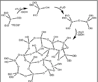
As an example of preparation of the sol of silica particles, silica precursors (silicon alkoxide) are mixed with a hydrolysis agent and a solvent; by condensation reactions a network based on Si-O-Si bridges, is achieved (Figure 2). 1 a
3
Figure 2. Schematic preparation of Silica Aerogels
Among all known aerogels, silica aerogels are the most popular one.
They possess a wide variety of extraordinary properties; many of them are registered in the Guinness Book of Records for Properties. 3a High porosity (~ 99%), high specific surface area
(~ 1000 m²/g), low density (~ 0. 002 g/cm³), low thermal conductivity (~ 0. 01 W/m·K), high optical transition (~ 99%), low refractive index (~ 1.05), low dielectric constant
(~ 1.0 -2. 0) and low sound velocity (100 m/s) are some of their exceptional properties that make them promising candidates for
4
many advanced applications. 3a-eKistler's later work involved
aerogels based on alumina, chromia and tin oxide. 1
Although most aerogels are inorganic, 2a-h many organic and
polymeric aerogels, 2i, j have also been developed.
The relevance of polymeric aerogels is mainly related to low cost, robustness, durability and easy processing typical of polymers. Polymeric aerogels are generally characterized, as the other aerogels, by chemically bonded three-dimensional networks. In fact, highly cross-linked aerogels are obtained by systems of resorcinol–formaldehyde, 4a-c melamine-formaldehyde, 4d-f
phenolic-furfural, 4c, 4g- ipolyurethane-dichloromethane, 5a cresol
formaldehyde, 5b phloroglucinol-formaldehyde, 5cepoxy-amine, 5d
1, 3-dimethoxybenzene or 1, 3, 5-trimethoxybenzene
formaldehyde, 5c, e, f hydroxylated benzene derivatives-alkyl or
aryl aldehydes, 5g-i and aromatic dianhydrides-aromatic diamines
or a combined aromatic and aliphatic diamines. 5 l, m
A schematic example of the reaction for the formation of chemically crosslinked polymeric gels is shown in Figure 3, which describes the resorcinol-formaldehyde reaction and explains the formation of a crosslinked polymer network. 4c Dry
resorcinol formaldehyde aerogels were lastly obtained by the supercritical drying gels with CO2.
5 aerogels in details. 4a, b
Figure 3. Schematic preparation of Chemically Crosslinked Polymeric Aerogels
In more recent years, polymeric aerogels based on thermoplastic
uncrosslinked polymers, where the knots of the
three-dimensional networks are physical, not formed by covalent chemical bonds but by small crystallites, have also been
obtained. 6-8 These physically cross-linked aerogels are generally
prepared by supercritical CO2 extraction of thermoreversible
organogels. 7-9 In particular hot polymer solution are cooled to
lower temperature where gelation occurs.
In this respect is necessary to say that besides aerogels another class of porous materials, is constituted by semicrystalline
6
thermoplastic polymers whose crystalline phase is nanoporous, i. e.
presents a density lower than the corresponding amorphous phase. 9, 10
These nanoporous crystalline polymers are able to absorb low molecular mass molecules also when present in traces and have been proposed for molecular separation, 11 sensor 12 and
catalysis 13 applications.
The preparation of aerogels with thermoplastic materials exhibiting nanoporous crystalline forms has allowed achieving a special class of physically cross-linked aerogels, where the crystallites that constitute the physical knots of the aerogel exhibit a nanoporous-crystalline form. 7 These nanoporous-crystalline
aerogels beside disordered amorphous meso and macro pores (typical of all aerogels) present also all identical nanopores of the crystalline phases.
In particular, monolithic aerogels based on the nanoporous-crystalline δ8a-e and ε8f forms of syndiotactic polystyrene (s-PS),
which include beside amorphous pores their typical crystalline nanopores (cavities and channels, respectively), have been obtained. The simplest preparation procedure is based on supercritical CO2 (scCO2) extraction of an organic solvent being
7 co-crystalline phases. 8, 12
The fast kinetics and high sorption capacity of VOCs by s-PS nanoporous-crystalline aerogels as well as their good handling characteristics make these new materials particularly suitable as a sorption medium to remove traces of pollutants from water and air. 8
Very recently, the presence of nanoporous crystalline modifications has been disclosed for another commercial thermoplastic polymer: poly (2, 6-dimethyl-1, 4-phenylene) oxide (PPO). 10a
Crystalline modifications, exhibiting largely different X-ray diffraction patterns, have been obtained for this polymer, by gel desiccation procedures as well as by solvent induced crystallization of amorphous films.
Both amorphous and semicrystalline samples of this commercial thermoplastic polymer exhibit a high uptake of large guest molecules (like, e. g., benzene or carbon tetrachloride), both from vapor phases and from diluted aqueous solutions. The semicrystalline PPO samples present guest solubility much higher than fully amorphous PPO samples.
However, the solvent extraction by supercritical CO2 from PPO
gels, with many different solvents, leads to powders rather than to aerogels. 10a
8
extremely interesting to make a preparation method of monolithic aerogels, including PPO nanoporous-crystalline phases.
Another interesting commercial polymer, considered in this study for the preparation of physically crosslinked polymeric aerogels, is the poly (2, 6-diphenyl-1, 4-phenylene oxide) (shortly indicated as PPPO).
This polymer is an excellent porous adsorbent for the trapping of many types of volatiles such as halogenated and aromatic compounds, 14a-c normal alkanes, 14a, d, e cycloalkanes, 14a ketones, 14a, d−e alcools, 14a, d-e and volatile fatty acids 14c mainly from air12a, d-e
but also from water. 6
Thus, as for most molecular sorption studies 14 PPPO is used as
a semicrystalline powder, is crucial to establish if the occurrence of a nanoporous crystalline phase could be at the origin of the high sorption properties of PPPO and explore the possibilty to obtain PPPO aerogels, in attempt to improve the already high sorption of this polymer.
Because of the above and of the emerging interest for these extraordinary materials, the first part of this study will focus on physically crosslinked polymeric aerogels, particularly on aerogels based on PPO and on PPPO, not described in literature previously. Furthermore in the first part is described
9
the preparation of polyethylene aerogels, also achieved for the first time.
The second part will focus on nanocomposites aerogels. In particular, will be examined syndiotactic polystyrene composites aerogels with:
Graphene oxide
Organically modified montmorillonite (OMMT).
Each chapter is closed with a summary that highlight the main achievements of the study. A graphical summary of the thesis structure is shown in Figure 4.
10
11
References
[1] a) S. S. Kistler, Nature 1931, 127, 741; b) S. S. Kistler, J. Phys.
Chem. 1932, 36, 52. b) H. Tamon, et al. Journal of Colloid and Interface Science, 1998, 197(2), 353-359.
[2] a) Schaefer, D. W. ; Keefer, K. D Phys. Rev. Lett. 1986, 56,
2199. b) Pajonk, G. M. Appl. Catal. 1991, 72, 217.
c) Mayer, S. T. ; Pekala, R. W. ; KaschmitterJ. L J. Electrochem.
Soc. 1993, 140, 446. d)Ward D. A. ; Ko E. I. J. Catal. 1994, 150,
18. e)Anderson, M. L. ; Stroud, R. M. ; Rolison, D. R. Nano
Letters 2002, 2, 235. f)Pierre, A. C. ; Pajonk, G. M. Chem. Rev.
2002, 102, 4243. g)Nielsen, T. K. ; Manickam, K. ; Hirscher, M. ;
Besen bacher, F. JensenT. R. ACS Nano 2009, 3, 3521.h)Wei, T. Y. ; Chen, C. H. ; Chang, K. H. ; Lu, S. Y. ; Hu, C. C. Chem.
Mater. 2009, 21, 3228. i) Pekala, R. W. J. Mater. Sci. 1989, 24,
3221.j) Pekala, R. W. ; Alviso, C. T. ; Kong, F. M. ; Hulsey, S. S.
J. Non-Cryst. Solids 1992, 145, 90.
[3] a) Fricke, J., & Emmerling, A. . Journal of Sol-Gel Science and
Technology, 1999, 13(1-3), 299-303. b) Fricke, J., & Reichenauer,
G. Paper presented at the Materials Research Society Symposia Proceedings, 1986 c) Gurav, J. L., et al. Journal of Nanomaterials,
2010. d) Hrubesh, L. W. Journal of Non-Crystalline Solids, 1998, 225
1), 335-342 (e) Soleimani Dorcheh, A., & Abbasi, M. H. Journal
of Materials Processing Technology, 2008, 199(1), 10-26.
12
US4997804 1991 (c)Pekala RW. J Mater Sci 1989; 24, 3221-3227. (d) Pekala, R. W. : US5081163 1992, (e)Pekala, R. W. : US5086085 1992, (f)Pekala, R. W. : US5476878 1995 (g) Pekala, R. W. : US5556892 1996 (h) Pekala, R. W. : US5744510 1998. (i) Pekala RW, Alviso CT, Lu X, Gross J, Fricke J. J. Non-Cryst
Solids, 1995; 188, 34-40.
[5] a)Biesmans G, Martens A, Woignier T, Phalippou J. ; J.
Non-Cryst Solids 1998; 225 64-68. b)Li W., Guo S. Carbon 2000, 38:
1520-1523. c) Baumann, T. F., Satcher, Jr., Joe, H., Gash, A. E. : US20050027027 (2005) d)Raman VI, Palmese GR. Colloids Surf
A Physicochem Eng Asp 2004; 241, 119-125. Rhine, W., Wang, J.
Begag, R. : US20040132845 2004. e) Baumann, T. F., Satcher, Jr., Joe, H., Gash, A. E. : US20046806299 2004. f) Baumann, T. F., Satcher, Jr., Joe, H., Gash, A. E. : US20077291653 (2007). g) Chenee, J. -P. P., Liege, R. P., Liege, N. J. : US20040241237(2004). h)Satcher, J. H., Baumann, T. F. : US20077285575 (2007). i) Dietz, S., Nguyen, V. T. : US20077167354 (2007). l) Rhine, W., Wang, J., Begag, R. : US20050131163 (2005). m) Rhine, W., Wang, J., Begag, R. : US20067074880 (2006).
[6]a) Jin, H. ; Nishiyama, Y. ; Wada, M. ; Kuga, S. Colloids and
Surfaces A: Physicochem. Eng. Aspects 2004, 240, 63 b) Gavillon, R. ;
Budtova, T. Biomacromolecules 2008, 9, 269 c) Miao, Z. J. ; Ding, K. L. ; Wu, T. B. ; Liu Z. M. ; Han B. X. ; An, G. M. ; Miao S.
13
D. ; Yang G. Y. Microporous and Mesoporous Materials 2008
111, 104 d) Robitzer, M. ; David, L; Rochas, C. ; Di Renzo, F. ;
Quignard, F. Langmuir 2008, 24, 12547 e)Quignard, F. ; Valentin, R. ; Di Renzo, F. New J. Chem. 2008, 32, 1300.
[7] a) Beaucage, G. ; Aubert, J. H. ; Lacasse, R. R. ; Schaefer, D.
W. ; Rieker, T. P. ; Erlich, P. ; Stein, R. S. ; Kulkarni, S. ; Whaley, P. D. Journal of Polymer Science: Part B PolymerPhysics 1996, 34, 3063 b) Dasgupta, D; Nandi, A. K. Macromolecules 2005, 36, 6504, c) Dasgupta, D; Nandi, A. K. Macromolecules 2007, 40, 2008 d) Cardea, S. ; Gugliuzza, A. ; Sessa, M. ; Aceto, M. C. ; Drioli, E. ; Reverchon, E. ACS Appl. Mater. Interfaces 2009, 1, 171. e) Daniel, C. ; Vitillo, J. G. ; Fasano, G. ; Guerra, G. ACS Appl. Mater.
Interfaces 2011, 3, 969.
[8] (a) Daniel, C. ; Alfano, D. ; Venditto, V. ; Cardea, S. ;
Reverchon, E. ; Larobina, D. ; Mensitieri, G. ; Guerra, G. Adv.
Mater. 2005, 17, 1515. (b) Guerra, G. ; Mensitieri, G. ;
Venditto, V. ; Reverchon, E. ; Daniel, C. PCT Int. Appl. 2005, WO 2005012402. (c)Malik, S. ; Rochas, C. ; Guenet, J. -M.
Macromolecules 2005, 38, 4888. (d) Malik, S. ; Roizard, D. ;
Guenet, J. -M. Macromolecules 2006, 39, 5957. (e) Daniel, C. ; Sannino, D. ; Guerra, G. Chem. Mater. 2008, 20, 577. (f) Daniel, C. ; Giudice, S. ; Guerra, G. Chem. Mater. 2009, 21, 1028.
[9] a) C. De Rosa, G. Guerra, V. Petraccone, B. Pirozzi,
14
Venditto, P. Musto, C. De Rosa, L. Cavallo, Chem. Mater. 2000, 12, 363c) G. Milano, V. Venditto, G. Guerra, L. Cavallo, P. Ciambelli, D. Sannino, Chem. Mater. 2001, 13, 1506; d) E. B. Gowd, N. Shibayama, K. Tashiro, Macromolecules 2006, 39, 8412; e) P. Rizzo, C. Daniel, A. De Girolamo Del Mauro, G. Guerra,
Chem. Mater. 2007, 19, 3864; f) V. Petraccone, O. Ruiz de
Ballesteros, O. Tarallo, P. Rizzo, G. Guerra, Chem. Mater. 2008,
20, 3663; g) A. R. Albunia, P. Rizzo, G. Guerra, Chem. Mater.
2009, 21, 3370; h) G. Guerra, C. Daniel, P. Rizzo, O. Tarallo, J.
Polym. Sci. Polym. Phys. Ed. 2012, 50, 305.
[10] a) C. Daniel, Longo, S., J. G. Vitillo, G. Fasano, G. Guerra,
Chem. Mater. 2011, 23, 3195; b) O. Tarallo, V. Petraccone, C.
Daniel, G. Fasano, P. Rizzo, G. Guerra, J. Mater. Chem. 2012, 22, 11672; c) M. Galizia, C. Daniel, G. Fasano, G. Guerra, G. Mensitieri, Macromolecules 2012, 45, 3604; d) C. Daniel, D.
Zhovner, G. Guerra, Macromolecules 2013, 46, 449; e) P. Rizzo, G. Ianniello, S. Longo, G. Guerra, Macromolecules2013, 46, 3995.
[11] a) C. Manfredi, M. A. Del Nobile, G. Mensitieri, G. Guerra,
M. Rapacciuolo, J. Polym. Sci. Polym. Phys. Ed. 1997, 35, 133; b) P. Musto, G. Mensitieri, S. Cotugno, G. Guerra, V. Venditto,
Macromolecules 2002, 35, 2296; c) K. P. O. Mahesh,
M. Sivakumar, Y. Yamamoto, Y. Tsujita, H. Yoshimizu, S. Okamoto, J. Membrane Sci. 2005, 262, 11; d) V. Venditto, A. De Girolamo Del Mauro, G. Mensitieri, G. Milano, P. Musto, P.
15
Rizzo, G. Guerra, Chem. Mater. 2006, 18, 2205; e) G. Mensitieri, D. Larobina, G. Guerra, V. Venditto, M. Fermeglia, S. Pricl, J.
Polym. Sci. Part B Polym. Phys. 2008, 46, 8.
[12] a) G. Mensitieri, V. Venditto, G. Guerra, Sens. Actuators B 2003, 92, 255; b) M. Giordano, M. Russo, A. Cusano, G.
Mensitieri, G. Guerra, Sens. Actuators B 2005, 109, 177; c) A. Cusano, A. Iadicicco, P. Pilla, L. Contessa, S. Campopiano, A. Cutolo, M. Giordano, G. Guerra, J. Lightwave Technol. 2006,
24, 1776; d) A. Buono, P. Rizzo, I. Immediata, G. Guerra, J. Am. Chem. Soc. 2007, 129, 10992; e) P. Pilla, A. Cusano, A.
Cutolo, M. Giordano, G. Mensitieri, P. Rizzo, L. Sanguigno, V. Venditto, G. Guerra, Sensors 2009, 9, 9816; f) M. Erdogan, Z. Ozbek, R. Capan, Y. Yagci, J. Appl. Polym. Sci. 2012, 123, 2414.
[ 13 ] A. Buonerba, C. Cuomo, S. O. Sanchez, P. Canton, A.
Grassi, Chemistry-A Eur. J. 2012, 18, 709.
[14] (a) Maier, I. ; Fieber, M. J. High Resolut. Chromatogr. 1988,
11, 566−576. (b) Jens Laaks, J. ; Jochmann, M. A. ; Schilling, B. ; Schmidt, T. C. Anal. Chem. 2010, 82, 7641−7648. (c) Kim, Y. -H. ; Kim, K. --H. Anal. Chem. 2012, 84, 8284−8293. (d) Alfeeli, B. ; Taylor, L. T. ; Agah, M. Microchem. J. 2010, 95, 259−267. (e) Alfeeli, B. ; Jain, V. ; Johnson, R. K. ; Beyer, F. L. ; Heflin, J. R. ; Agah, M. Microchem. J. 2011, 98, 240−245. (f) Oen, A. M. P. ; Breedveld, G. D. ; Kalaitzidis, S. ; Christanis, K. ;
16
(g) Barrero-Moreno, J. M. ; Tirendi, S. ; Reniero, F. ; Giordano, G. ; Kotzias, D. Rapid Commun. Mass Spectrom. 2008, 22, 471−476. (h) Leva, P. ; Katsoyiannis, A. ; Barrero-Morero, J. ; Kephalopoulos, S. ; Kotzias, D. J. Environ. Sci. Health, Part B 2009, 44, 51−57.
17
Part I : Physically
Crosslinked Polymeric
18
Chapter 1
Physically Crosslinked polymeric aerogel:
State of the Art
1.1 Introduction
Gels consist of three-dimensional network structures swollen by a liquid. As mentioned above, for chemical gels, the cross-links that give rise to this network are covalent bonds, 1 whereas, for
physical gels the connectedness between polymer chains is achieved by intermolecular physical bonding forming junction zones that can be created and removed by cooling and heating, respectively. 2
In particular, for most physical gels, 3, 4 the junction zones are
crystalline regions, organized as fibrils or uncorrelated lamellar platelets, which form monolithic structures because of entanglement.
As introduced, the most efficient method to obtain monolithic aerogels (in the early papers also called nano-structured low density polymer foams)3a from monolithic physical polymer gels
is the solvent extraction by supercritical carbon dioxide(scCO2 ). 5, 3a, e–j, 4b–h
19
based on uncrosslinked polymers obtained by scCO2 extraction
of thermoreversible organogels, based on nitrocellulose, 5, 3j
isotactic polystyrene (i-PS), 3c poly(acrylonitrile), 3c
polyvinylidenefluoride (PVDF), 3d, i poly(vinylidene
fluoride-cohexafluoropropylene) P(VDF-HFP), 3g polylactic acid, 3e, f
isotactic poly(4-methyl-pentene-1) (i-P4MP1), 3h and hydrogels,
based on gelatin, 5 alginate, 4e, d, h chitosan 4f, g starch, 4c and
cellulose, 4a, b or by preparing gels of semi dilute polymer
(polyethylene3a, b and isotactic polypropylene 3b) solutions in a
supercritical solvent.
As for aerogels from organogels it has been recognized, since the pioneering studies of Beaucage et al., 3c that their stability is
associated with their crystalline phase morphology. In fact, polymer crystallization in solutions leading to spherulitic or other globular morphologies produce unstable gels, 19h, 2b-e
which, if formed, are crushed as a consequence of drying. 19h
On the other hand, stable physical polymeric aerogels are always semicrystalline and their crystalline morphology can be described in terms of uncorrelated lamellar platelets or, more often, of fibrils. This is observed, for instance, for the monolithic aerogels based on i-P4MP1, PVDF, P(VDF-HFP) and s-PS and shown by photographs and SEM images in Figure 2 for a 0. 2 gg − 1 i-P4MP1 gel in 1, 3, 5-trimethilbenzene. 3h
20
Figure 1.1. Photographs of cylindrical monolithic organogels based on i-P4MP1, of the corresponding aerogels obtained by supercritical drying and
SEM images of the aerogels.
furthermore, important volume shrinkages have been observed with aerogels obtained from gels which undergo a crystalline phase transition during the extraction process. For example, i-P4MP1 is characterized by a complex polymorphic behavior that includes four crystalline phases as well as several cocrystalline phases with low-molecular-mass guest molecules; nevertheless only for a particular crystalline phase gels (Form I, for instance obtained with 1, 3, 5-trimethylbenzene), which maintain this crystalline phase also in their aerogels, both the dimension and shape of the native gel are not altered by the solvent extraction procedure. It is reasonable to expect that, also for other polymers, crystalline phase transitions could be detrimental to the dimensional stability of the physical aerogels.
21
1.2
How to prepare physically crosslinked
polymeric aerogels: Sol - Gel Technology
Generally sol-gel technology describes those processes where a precursor (or a precursors mixture) forming a colloidal solution, which end up with a solid network. 8 Sol-gel technology has
proved to be a versatile and valuable method for production and processing of materials. Metallic, organic, inorganic and hybrid materials can provide valid precursors that can be used for this process. The end products can range from highly advanced materials to materials of general daily use. The importance of the sol–gel process arises from two main causes:
1) production of highly pure materials; 2) creation of novel valuable materials 9
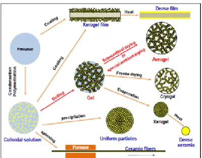
Figure 1.2 shows a general sol-gel technology sketch of the main most commonly used steps in the sol-gel processes.
22
Figure 1.2. General steps involved in the processing of materials using the sol-gel technology and some possible final products structure. For a broad number of applications, the gel porous network is the key feature for their use. Hence, as aforementioned, it is important to remove the solvent from the network in a way that preserved the internal textural properties of the gel. During solvent evaporation from the gel network the curvature of vapor-liquid interface changes. The curvature of the meniscus decreases with time (Figure 1.3).
23
Figure 1.3. Change in liquid-vapor meniscus radius as a function of drying time at the pore surface.
As a result capillary forces take place. The pressure difference between the liquid and vapor phase can be given by Laplace's equation:
Eq. 1
Where σ is the liquid/vapor interfacial surface tension, R is the meniscus radius and θ is the contact angle at which the liquid/vapor interface meets the solid surface. Accordingly the gel structure is subject to compression stresses. Because of the high capillary pressure induced upon solvent evaporation and the fragility of the gel structure, cracks and shrinkages are obtained. Hence, a reduction of the textural properties of the dry gel will be observed.
However, it is possible to reduce the capillary pressure induced during drying by using a solvent which has a low surface tension
24
value. By means of solvent exchange it is possible to reduce the capillary forces using solvent with lower surface tension.
In particular, as mentioned above, monolithic aerogels based on uncrosslinked polymers have been obtained by scCO2.
Mechanism of scCO2 gel drying involves first the formation of a pressurized expanded liquid between scCO2 and the organic
solvent and, secondly its progressive transformation in a supercritical mixture, as long as the concentration of CO2 in the
mixture increases. The supercritical mixture is characterized by a near zero surface tension; this characteristic avoids gel nanostructure collapse. In the subsequent part of the process, the supercritical mixture is progressively removed by continuous flushing of scCO2 in the pressurized vessel. Therefore, for a successful processing of polymeric gels, the liquid solvent used to produce the gel, should be soluble in scCO2 at the processing
conditions and solvent elimination has to be performed at temperatures and pressures above their mixture critical point (MCP); i. e., at conditions of complete miscibility between solvent and scCO2. From a technological point of view, these
requisites are relatively simple to be obtained, since the organic solvents ordinarily used (for example, dimethyl sulfoxide, acetone, ethanol, halogenated and aromatic solvents) show a large affinity with scCO2 and the MCP is located at pressures
25
1.3
Polymeric Aerogels with
Nanoporous-Crystalline Phases as Physical Cross-Links
It is well known that for a large variety of inorganic, metalorganic as well as organic compounds, the removal of guest molecules from cocrystals can generate nanoporous crystalline phases. 10
As for polymer cocrystalline phases, the removal of the low-molecular-mass guest molecules generates host chain rearrangements, generally leading to crystalline forms that (as usual for polymers) exhibit a density higher than for the corresponding amorphous phase. 3h, 11 However, in few cases (to
our knowledge, up to now only for s-PS12 and PPO13), by using
suitable guest removal conditions and preferably extraction by scCO2, 14 nanoporous crystalline forms, exhibiting a density
definitely lower than for the corresponding amorphous phases, can be obtained.
1.4 Aerogels with the Nanoporous δ and ε Forms
of s-PS
s-PS has been extensively studied and characterized in recent years. This polymer has a complex and widely studied polymorphism, it has 5 crystal structures, α, β, γ, δ, ε, and a wide variety of cocrystal structures with different low molecular
26 weight molecules. 15
The removal of the low-molecular-mass guest molecules from s-PS co-crystals can generate two different nanoporous-crystalline phases.
The first polymeric nanoporous-crystalline form, the δ form of s-PS, 12a– d was patented in 1994. Chains in the helical s(2/1)2
conformation are packed in a monoclinic unit cell with axes a = 1.74 nm, b = 1.185 nm, c =0. 77 nm, and γ = 117 ° whose density is of 0. 98 g cm -3, i. e., definitely smaller than that one of
the amorphous phase (1.05 g cm -3). 12a The structure presents
isolated cavities having a volume close to 0. 125 nm3, confined
by layers of closely packed alternated enantiomorphous helices, parallel to the ac plane (Figure 1.4 A and A ′ ). 12a, c
The crystalline cavities are in a number equal to the number of chains and generally can contain one or two guest molecules. 12a, c It is worth adding that the cavity is rather flat, i. e., presents its
maximum dimension ( ≈ 0. 8 nm) nearly perpendicular to the polymer chain axis, while its minimum dimension ( ≈ 0. 3 nm) is essentially along the c axis (Figure 1.4 A and A' ). 12c
The nanoporous ε phase of s-PS, 12e– g discovered in 2007, 12e
presents an orthorhombic unit cell with axes a =1.61 nm, b = 2. 18 nm, and c = 0. 79 nm (Figure 1.4 B, B ′ ). 12f Four chains of
s-PS in the s(2/1)2 helical conformation are included in the unit cell, whose density is 0. 98 g cm − 3, i. e., very close to the density
27 + +
-A
B
B’
A’
Figure 1.4. A, B) Top and A ′, B ′) lateral views of the crystalline structures of the two nanoporous crystalline forms of s-PS. For the A, A ′) δ and B, B ′)
ε forms, the porosity is distributed as cavities and channels, respectively. In (A), the quadrupolar electrostatic field of the cavity is indicated by + and – signs. Reproduced with permission. 12b Copyright 2012, John Wiley & Sons
Ltd.
The crystal structure is characterized by channel-shaped cavities crossing the unit cells along the c axis and delimited, along b axis, by two enantiomorphous helical chains (Figure 1.4 B, B ′). In these channels, guest molecules are generally hosted with their longer molecular axis roughly parallel to the polymer chain axis.
28
As a consequence of guest sorption in both s-PS nanoporous-crystalline phases, many different conanoporous-crystalline forms can be obtained, which have been classified as δ-clathrates, 15 δ
-intercalates, 16 or ε clathrates. 17
Clathrates present isolated guest molecules in crystalline cavities and channels of δ and ε forms, respectively, while intercalates present layers of guest molecules alternated with closely packed layers of alternated enantiomorphous helices that characterize the δ form(Figure 1.4 A).
X-ray diffraction, neutron diffraction, and differential scanning calorimetry characterizations have allowed clarifying that the junction zones of s-PS gels, when prepared by solvents being suitable guests of s-PS cocrystalline forms, 18 are constituted by
cocrystalline phases. In particular, the studied gels present δ -clathrate18a, d, e, g or δ -intercalate 18a, b, c, f, g phases.
ScCO2 drying of these gels not only removes solvent molecules
leading to stable monolithic aerogels but also removes the solvent molecules being guest of the cocrystalline phase, thus leading to nanoporous-crystalline δ phases (Figure 1.5A), exhibiting a fibrillar morphology (Figure 1.5 A', fibrils of 50–100 nm). 3b, 5, 19
High-temperature scCO2 extraction procedures 14f on highly
crystalline gels (like those exhibiting the s-PS cocrystalline phase with DCE), 16c also allow obtaining high-porosity aerogels
-29
form 24(not shown here), i. e., aerogels exhibiting dense rather
than nanoporous-crystalline s-PS phases as junction zones. 19f
These aerogels present a fibrillar morphology with fibril diameters in the range 30–150 nm, similar to those observed for δ -form aerogels, and hence present the disordered porosity of the aerogels whereas do not present the three-dimensionally ordered crystalline nanopores. 19f
Monolithic aerogels exhibiting the nanoporous-crystalline ε 12e–g
form of s-PS, with its typical crystalline channels, have also been obtained. 19f These aerogels have not obtained by direct gel
drying procedures, due to the lack of gels exhibiting ε -clathrates. 17 Robust monolithic ε -form aerogels (Figure 1.5 C,
C′ ) are instead obtained by treatments of γ -form aerogels (Figure 1.5 B and B ′ ) with chloroform, followed by solvent extraction by scCO 2 at 40 ° C and 200 bar. 19f
30
Figure1.5. X-ray diffraction patterns (Cu-Kα radiation) and SEM images of aerogels as obtained from a s-PS gel prepared in 1, 2-dichloroethane (DCE) at C pol = 0. 05 g g − 1, after extraction by scCO2 : A, A ′ ) at 40 ° C, 200 bar
( δ -form); B, B ′ ) at 130 ° C, 200 bar ( γ -form); C, C ′ ) at 130 ° C 200 bar, followed by room-temperature treatments with chloroform and a second
solvent extraction by scCO2 at 40 ° C ( ε -form).
It is worth adding that the density and the total porosity of the physical aerogels can be easily controlled, in wide ranges, by simply changing the gel polymer concentration.
This is shown, for instance in Figure 1.5 A, for aerogels obtained from s-PS/toluene gels where the percentage of
31
porosity P was estimated from the mass/volume ratio of the aerogel using the relation shown in equation 2:
Eq. 2
100 1 (2) pol app P
where ρ pol is the density of the polymer matrix (e. g., equal to 1.02 g cm − 3, for δ -form s-PS samples with a crystallinity of
nearly 40%) and ρ app is the aerogel apparent density calculated
from the mass/volume ratio of the monolithic aerogels.
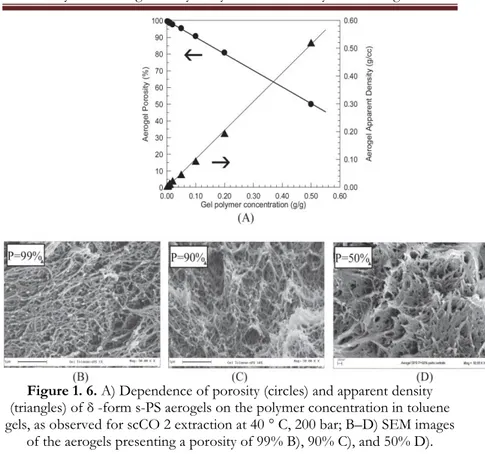
The SEM images of Figure 1.6 B–D show that, while the aerogel porosity changes in a wide range, the morphology remains essentially unaltered, with fibrils maintaining diameters in the range 50–100 nm.
32
Figure 1. 6. A) Dependence of porosity (circles) and apparent density (triangles) of δ -form s-PS aerogels on the polymer concentration in toluene gels, as observed for scCO 2 extraction at 40 ° C, 200 bar; B–D) SEM images
of the aerogels presenting a porosity of 99% B), 90% C), and 50% D). As generally done for porous materials, the surface area of the obtained aerogels has been studied by BET experiments like those reported in Figure 1.7 and Table 1. From these and other analogous experiments, it is possible to conclude that N2
sorption ability and surface area of s-PS samples are: i) higher for samples including the nanoporous crystalline phases ( δ or ε ) than for the corresponding samples exhibiting dense crystalline phases ( α, β or γ );
ii)highest for samples including the nanoporous-crystallineδ phase;
33
iii) always higher for aerogels than for powders; iv) increasing with the aerogel porosity.
Figure 1.7. Volumetric N2 adsorption isotherms recorded at 77 K for s-PS powders (empty symbols) and aerogels (filled symbols), presenting different crystalline phases. For the aerogels the porosity is indicated as P, close to
each curve. Reproduced with permission. 36Copyright 2010, American Chemical Society.
34
Table 1.1. N2 sorption at p/p° = 0. 1, expressed as cm3 g-1, and BET surface area, expressed as m2 g-1 for the s-PS powders and aerogels of Figure
6.
It is worth adding that aerogels based on other polymers, exhibiting dense crystalline phases, present surface areas similar to those observed for the β -form s-PS aerogels and much lower than those obtained for nanoporous-crystalline ( δ and ε ) s-PS aerogels. For instance, SBET is lower than 90 and 70 m 2 g − 1 for
all the prepared i-P4MP1 3h and PVDF 3i aerogels, respectively.
s-PS sample N2 sorption at p/p° = 0. 1 (cm3 g1) BET (m2 g-1)
γ-powder 0. 3 4 δ-powder 9 43 β-aerogel (P=91%) 14 70 ε-aerogel (P=88%) 47 230 δ-aerogel (P=90%) 56 290 δ-aerogel (P=98%) 69 348
35
Chapter 2
Monolithic nanoporous–crystalline aerogels based
on Poly(2, 6-dimethyl-1, 4 phenylene)oxide and
Syndiotactic Polystyrene
2. 1 Introduction
As discussed in the introduction, very recently the presence of nanoporous crystalline modifications has been disclosed for another commercial thermoplastic polymer: poly(2, 6-dimethyl-1, 4-phenylene)oxide (PPO). 13a
Figure 2. 1. Chemical structure of PPO repeating unit
However, extraction from PPO gels of the solvent, independently of its chemical nature and of the extraction procedure, leads to powders rather than to aerogels. 13a
In this chapter, the preparation of monolithic aerogels, including PPO nanoporous–crystalline phases, is reported.
The described preparation method is based on the formation in the gels (and in the derived aerogels) of fibrillar crystalline morphology as a consequence of blending PPO with s-PS. The
36
method, by using gels with suitable PPO/s-PS compositions, also allows the formation of monolithic aerogels that include, beside amorphous nanopores, nanoporous–crystalline phases of both PPO and s-PS.
2. 2 Preparation and structural characterization of
PPO/s-PS aerogels
X-ray diffraction patterns of physical PPO gels with a polymer content in the range 30–40 wt%, with four different solvents, are shown in Figure 2. 2 A–D. All these patterns show, beside broad amorphous halos associated with the solvent and the polymer amorphous phase, well-defined crystalline peaks associated with the three-dimensional physical networks holding up the gel. In particular, the gels including decalin and α-pinene (Figure 2. 2 A and 2. 2 B, respectively) exhibit diffraction peaks of the corresponding co-crystalline phases with PPO.
In particular, the 101, 110, 102, 200, 201, 211, 220 and 221 reflections of the PPO/α-pinene cocrystalline form, located at 2ϴ Cu-Kα ~ 8. 9°, 10. 5°, 13. 1°, 15. 0°, 15. 8°, 17. 5°, 21.3° and
37
Figure 2. 2. X-ray diffraction patterns (Cu-Kα radiation) of PPO gels (PPO content 30–40 wt%), prepared with different solvents (A–D), and of the
corresponding powders, as obtained by complete solvent extraction by scCO2 (A'–D'): (A, A') in decalin; (B, B') in α-pinene; (C, C') in benzene; (D,
D') in carbon tetrachloride.
As for the gel with decalin, peaks at 2ϴ Cu-Kα ~ 9. 1°, 10. 6°, 12.
7°, 17. 4° and 21.8° are observed (Figure 2. 2 A), which, from analogy with the X-ray diffraction pattern of the co-crystalline phase with α-pinene, can be indexed as 101, 110, 102, 211 and 220–221, respectively. The gels including CCl4 (Figure 2. 2 C)
38
different from those of the co-crystals with α-pinene and decalin gels but also definitely different from each other as well as from those of the known PPO crystalline modifications. 22, 24
The solvent removal from all these physical gels by supercritical carbon dioxide does not lead to aerogels, 13a as observed instead
for many other thermoplastic polymers, 19 but only leads to
powders. These powders can be amorphous (Figure 2. 2A') or can exhibit a PPO crystalline modification (Figure 2. 2 B'–D'). In particular, as a consequence of complete benzene and CCl4
removal from their gels (Figure 2. 2 C' and 2. 2 D'), the limit nanoporous crystalline modifications with highest and lowest diffraction angles (similar to those described in the first and last columns of Table 1 of ref. 13a) are obtained, respectively. It is worth noting that the X-ray diffractions of the gels of Figure 2.2 C, D are similar to those of the corresponding nanoporous– crystalline phases of Figure 2.2 C', D'. This similarity suggests the presence in these gels of co-crystalline phases, being structurally related to the corresponding nanoporous–crystalline phases.
In particular, the shift to a higher 2ϴ value (from 3. 7° up to 4. 55° and from 4. 9° up to 5. 15°) observed for the lowest diffraction peak, as a consequence of CCl4 and benzene removal
from their PPO gels, suggests unit cell reductions as a consequence of removal of guest molecules from the
co-39 crystalline phases.
Hence, the present results confirm that, independently of the nature of the solvent in the gels and of the nature of the crystalline phase holding up the gel, solvent removal procedures lead to powders or extremely brittle samples rather than to robust aerogels.
This is shown for instance for the PPO gel in 1,2- dichloroethane with a polymer content of 20 wt%, in Fig. 2. 3.
Figure 2. 3. Photographs of pieces of PPO gel prepared in 1, 2-dichloroethane with a polymer concentration of 20 wt%, before and after
complete solvent extraction via supercritical carbon dioxide (units on the ruler are cm).
Monolithic physically crosslinked aerogels can be instead easily prepared from mixed PPO/s-PS gels, by the usual scCO2 extraction procedure, provided that the s-PS fraction is higher than 0. 05.
s-PS has been selected because it easily forms aerogels 19 and
because PPO and s-PS dissolve in the same solvents. In addition PPO and s-PS are fully miscible in their amorphous phases. 25
40
with a polymer content of 20 wt%, is shown in Figure2. 4.
Figure 2. 4. Photographs of pieces of 90/10 w/w PPO/s-PS gels prepared in 1, 2-dichloroethane with a polymer concentration of 20 wt%, before and after complete solvent extraction via supercritical carbon dioxide (units on
the ruler are cm).
The obtained aerogels exhibit a toughness comparable to those of s-PS aerogels and the monoliths do not break even after heavy handling.
The X-ray diffraction patterns of aerogels obtained from gel in 1, 2-dichloroethane18 (DCE) with a polymer content of 20 wt%
are shown, for instance, in Figure 2. 5.
The s-PS aerogel (Figure 2. 5A) shows strong reflections located at 2ϴ (Cu-Kα) ~ 8. 3° (010), 20. 7° and 23. 5°, indicating the presence of the nanoporous δ-form. 14
The PPO/s-PS aerogels, for low PPO contents (xPPO = 0. 25, Figure 2. 5B), show only the crystallinity of the δ form of s-PS. For intermediate polymer composition (e. g. xPPO = 0. 50, Figure
2.5C) both s-PS and PPO crystallinities are clearly present. As for the PPO crystallinity, well apparent for xPPO > 0.5,
41
PPO powder, as obtained by DCE removal from the corresponding gel, diffraction peaks at 4. 95°, 7. 65°, 12. 3°, 16. 1°, 21.5° are observed (Figure 2. 5F), which are not far from those observed for powders obtained by desiccation of benzene gels (Figure 2. 2 C', indicated as high limit diffraction angles in the first column of Table 1 in ref. 13a).
As the PPO fraction decreases, a progressive shift of the PPO crystalline peaks is observed and for xPPO = 0. 50 (Figure 2. 5C)
the diffraction peaks are observed at 4. 4°, 7. 15°, 11.2°, 15. 0° and 18. 1°, i. e. at 2ϴ values lower than those of powders obtained by desiccation of carbon tetrachloride gels (Figure 2. 2 D', indicated as low limit diffraction angles in the last column of Table 1 in ref. 13a). The formation of PPO physical aerogels, already in the presence of small amount of s-PS, clearly indicates a strong influence of s-PS on PPO crystallization.
42
Figure 2. 5. X-ray diffraction patterns (CuK radiation) of PPO/s-PS gels in DCE, prepared with polymer content of 20wt%, after complete solvent extraction by scCO2, for different PPO fraction: (A) s-PS aerogel; aerogels with (B) xPPO = 0. 25, (C) xPPO = 0. 50, (D) xPPO = 0. 75, (E) xPPO = 0. 9; (F) PPO powder. For some patterns (C and F), diffraction peaks of PPO and
s-PS ( form) are labeled by bold and italics numbers, respectively. This influence is confirmed by the remarkable shift between PPO crystalline modifications (approximately from the limit
5 10 15 20 25 30 35 23,5 (A) s-PS (F) PPO (E) xPPO=0,90 (D) xPPO=0,75 (C) xPPO=0,50 (B) xPPO=0,25 In te nsi ty (a .u .) 2 deg) 4,5 7,3 8,35 11,2 18,1 20,6 12,3 7,6 4,8 21,4 16,0
43
modification with lowest diffraction angles toward the limit modification with highest diffraction angles), which is induced by the increase of the s-PS content in the blend (Figure 2. 5). The observed s-PS influence on PPO crystallization is not surprising, due to the well-known miscibility of the two polymers in their amorphous phases, as already mentioned previously. 25
In fact, it has been clearly established that PPO is able to alter the s-PS polymorphic behavior, favoring the densest and thermodynamically stable β crystalline form, 26 both for melt
crystallization25a and for solvent-induced crystallization from the
amorphous state. 25b
The patterns of Figure 2. 5 show that, in turn, s-PS is able to alter the PPO polymorphic behavior favoring, for solution crystallization, the crystalline modifications
exhibiting highest diffraction angles.
Scanning Electron Microscopy (SEM) images of some of the samples of Figure 2. 5 are shown in Figure 2. 6. The differences between the morphologies of the s-PS and PPO semicrystalline samples prepared in the same conditions are remarkable.
44
Figure 2. 6. SEM images of samples, as prepared from DCE gels with polymer content of 20wt%, after complete solvent extraction by scCO2: (A) s-PS form aerogel; (B) aerogel with xPPO = 0. 5; (C, C’) aerogel with xPPO =
0. 90; (D) PPO powder.
In fact, the δ form s-PS aerogel (Figure 2. 6A) presents a fibrillar morphology with fibril diameters of 60–150 nm, while the PPO nanoporous–crystalline powder exhibits granules of micrometric size, possibly constituted by aggregates of spherulites (Figure2. 6D). The SEM images of the aerogels obtained from PPO/s-PS blends (Figure 2. 6B, C) clearly show the maintenance of the fibrils typical of s-PS aerogels, together with a size reduction of the PPO granules (whose diameter becomes roughly lower than 1 mm). Hence, the miscibility between the amorphous phases of PPO and s-PS leads to finer PPO morphologies. It is reasonable
45
to hypothesize that the maintenance of the fibrillar morphology of the s-PS crystalline phases in mixed gels and aerogels (Figure 2. 6B, C) makes for feasible PPO-rich monolithic aerogels. Monolithic aerogels can be obtained from PPO/s-PS gels for a large range of polymer concentrations. Infact aerogels from gels with 5, 10, 20 and 30 wt% of polymer, with xPPO = 0. 50, have
46
2.3 Properties of aerogels based on
nanoporous-crystalline PPO
Total surface areas and micropore areas, as obtained from N2
isotherms (BET experiments) for the mixed PPO/s-PS aerogels are compared in Table 2.1 and Figure 2.7. The surface area increases with the PPO content (Figure 7A), but only for aerogels with crystalline PPO. In fact, for instance, the sample with xPPO = 0. 25 exhibiting only the s-PS crystallinity (Figure 2.
5B) shows a surface area close to that one of the pure s-PS aerogel. A linear increase of the surface area of the aerogels is instead observed with their content of crystalline PPO (xPPO, crys),
as clearly shown by Figure 2. 7B.
The predominant contribution of PPO crystallinity to the aerogel surface area is also confirmed by comparing aerogels exhibiting equal PPO content. In fact, the high-porosity PPO/s-PS - 50/50 wt% aerogel prepared from diluted gels (Cpol = 5
wt%, 7th line in Table 2. 1), which present a low degree of
crystallinity, exhibit surface area nearly three times lower than for the denser highly crystalline aerogels, as obtained from more concentrated gels (Cpol = 10-30 wt%, last three lines in Table 2. 1).
47
aTotal area evaluated following the BET model in the standard 0. 05 < P/P0
< 0. 25 pressure range.
bMicropore area obtained from the t-plot.
Table 2. 1. Total surface area (SBET) and micropore area (Smicro), expressed as m2 g-1, of the polymeric aerogels, as obtained for PPO/s-PS blends presenting different PPO weight fractions (xPPO), as prepared from DCE gels
presenting different polymer content (Cpol). The aerogel fraction constituted by crystalline PPO (xPPO, crys), as evaluated from the patterns of Figures 2 and
4, and the degree of crystallinity relative to the PPO fraction (xPPO), as
evaluated by the X-ray diffraction patterns of Figures 2 and 4, are also indicated.
xPPO Cpol
(wt%)
xPPO, crys SBETa
(m2 g-1) Smicrob (m2 g-1) xPPO (%) s-PS 20 0 206 27 0 0. 25 20 0 217 49 0 0. 5 20 0. 24 337 118 48 0. 75 20 0. 27 341 141 36 0. 9 20 0. 53 483 172 58 PPO (powder) 25 0. 59 535 195 59 0. 5 5 0. 08 112 19 15 0. 5 10 0. 20 273 92 39 0. 5 20 0. 24 337 118 48 0. 5 30 0. 18 343 108 35
48
Particularly interesting is the comparison of the dependence of
SBET on the apparent density for s-PS and PPO/s-PS aerogels,
which is shown in Figure 2. 7C. In fact, while for s-PS aerogels the surface area, SBET, increases as expected when the density
decreases, the opposite unexpected behavior is observed for the PPO/s-PS aerogels. This behavior can be rationalized by the achievement of maximum content of nanoporous-crystalline phase of PPO only for denser PPO/s-PS aerogels (Cpol 10 wt%, Table 2. 1).
49
Figure 2. 7. Surface area (SBET, m2 g-1) of PPO/s-PS aerogels (prepared from DCE gels and after complete solvent extraction by scCO2), as evaluated by the BET model in the standard 0. 05, P/P0, 0. 25 pressure range: (A, B) from gels with a polymer content of 20 wt% (aerogel apparent density of 0. 2 g cm -3) versus the PPO fraction (xPPO; A) or versus the crystalline PPO fraction
(xPPO, crys; B); (C) versus the aerogel apparent density, for xPPO = 0. 50.
0,0 0,1 0,2 0,3 0,4 0,5 0,6 0,7 0 100 200 300 400 500 -0,1 0,0 0,1 0,2 0,3 0,4 0,5 0,6 0,7 0,8 0,9 1,0 0 100 200 300 400 500 0,00 0,05 0,10 0,15 0,20 0,25 0,30 0 100 200 300 xPPO,crys (B) SBET (m 2 /g ) xPPO SBET (m 2 /g ) S BET (m 2 /g ) (A) Apparent density (g/cm3 ) (C) sPS PPO/sPS,50/50
50
For these monolithic PPO-based aerogels, exhibiting high surface areas (up to 350-500 m2 g-1), also for densities higher
than 0.2 g/cm3, the uptake of pollutant molecules as guest of
the nanoporous-crystalline phases is expected to be large, mainly if expressed as content per volume rather than per weight. The chosen pollutants for sorption test are the carbon tetrachloride (CCl4 ) and 1,2 dichloroethane (DCE). The reasons
which led to this choice are described in the following paragraphs.
2. 3. 1 Carbon tetrachloride
Carbon tetrachloride is readily volatile at ambient temperature and degrades very slowly, (85 years 27i)so it has gradually
accumulated in the environment.
The primary routes of potential human exposure to carbon tetrachloride are inhalation, ingestion, and dermal contact. The general population is most likely to be exposed to carbon tetrachloride through air and drinking water. In 1988, EPA’s Toxics Release Inventory listed 95 industrial facilities that produced, processed, or otherwise used carbon tetrachloride and reported environmental releases of carbon tetrachloride totaling 3. 9 million pounds (TRI 2009).
Exposure to carbon tetrachloride may also occur by dermal con-tact with tap water (e. g., during bathing). Surveys have found that about 99% of all groundwater supplies and 95% of all
sur-51
face-water supplies contain carbon tetrachloride. Exposure to carbon tetrachloride by ingestion may occur through consumption of contaminated drinking water or food. 27a
In this regard, damage to a prolonged exposure to high concentrations of carbon tetrachloride can affect the central nervous system, degenerate the liver 27b and kidneys27c , could
result in cancer 27f ,coma and even death. 27d
In 2008, a study of common cleaning products found the presence of carbon tetrachloride in "very high concentrations" (up to 101 mg/m3) as a result of manufacturers' mixing of
surfactants or soap with sodium hypochlorite (bleach). 27g
Carbon tetrachloride is also both ozone-depleting27h and
a greenhouse gas. 27i
2.3.2 1, 2-Dichloroethane
Dichloroethane (DCE) is toxic (especially by inhalation due to its high vapour pressure), highly flammable, and carcinogenic. 28a
Its high solubility and 50-year half-life in anoxic aquifers make it a perennial pollutant and health risk that is very expensive to treat conventionally, requiring a method of bioremediation. The general population is exposed to 1,2-dichloroethane primarily from inhalation of ambient air, particularly near point sources. Other potential routes of exposure for the general population include ingestion of DCE in contaminated drinking
52
water or food items and dermal absorption. In addition, inhalation exposure may occur from DCE that has volatilized from water during activities such as cooking, bathing, showering, and dishwashing, if DCE is in the water supply. Occupational exposure to this pollutant occurs through inhalation and dermal contact with the compound at workplaces where it is produced or used. Children are expected to be exposed to DCE by the same routes as adults. 28b
For these reasons, a material suitable to absorb these pollutants, even at low concentrations, is very interesting.
For the selected pollutants sorption measurements from vapors at low activity and from diluted aqueous solutions have been carried out with these PPO rich aerogels.
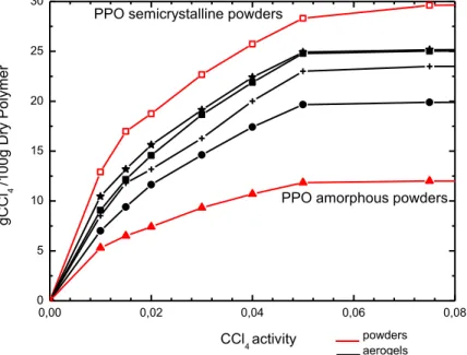
In Figure 2. 8 are reported the CCl4 sorption experiments at
35°C at pressures lower than 0. 08 P/P0 for s-PS/PPO aerogels
with different content of PPO, a pure δ s-PS aerogel and amorphous and semicrystalline PPO powders. We can observe that the sorption capacity of pure semi-crystalline PPO is higher than amorphous PPO and than s-PS δ aerogel. In particular at 0.01 P/Po the CCl4 uptake in the semi-crystalline PPO samples is
c.a 2 times higher than δ s-PS and 3 times higher than amorphous PPO.
The sorption results obtained with PPO-s-PS aerogels can be explained on the basis of X-ray diffraction patterns reported in
53 Figure2. 5.
s-PS/PPO aerogel with χPPO=0.25 shows a lower sorption
capacity than the s-PS δ aerogel. This can be clearly explained by the absence of PPO crystallization in these condition as shown in Figure2. 5B which leads to a sorption capacity lower than the s-PS δ phase. For PPO contents of χPPO=0. 50, χPPO=0. 75 the
sorption uptakes are similar and are intermediate between the uptakes of pure PPO and d s-PS.
Figure 2. 8. CCl4 sorption experiments at 35°C at pressures lower than 0. 08 P/P0 on : amorphous PPO(red solid triangles); s-PS/PPO aerogel χPPO=0. 25 (black solid circles); δ s-PS aerogel (black plus symbols); s-PS/PPO aerogel
χPPO=(black solid squares); s-PS/PPO aerogel χPPO=0. 75 (black stars symbol); semicrystalline PPO(red empty squares)
0,00 0,02 0,04 0,06 0,08 0 5 10 15 20 25 30
PPO semicrystalline powders
aerogels g C C l4 /1 0 0 g D ry Po lyme r CCl4 activity powders
54
In order to further characterize the sorption capacity and kinetics of s-PS/PPO aerogels and to assess possible uses of this new material, sorption measurements of diluted organic compounds from diluted aqueous solutions have been conducted at room temperature. In particular the equilibrium uptake of CCl4 and DCE from diluted aqueous solutions has
been investigated for s-PS/PPO aerogels with χPPO=0. 50
(Cpol=20%) and for δ s-PS aerogel (Cpol=1%).
In Figure 2.9 are reported the FTIR spectra a s-PS/PPO aerogel (A) and of a δ s-PS aerogel (B) before (black curves) and after (red curves) immersion in a CCl4 aqueous solution at 10 ppm.
55
Figure2. 9 FTIR spectra of s-PS/PPO aerogel (χPPO=0. 5) Cpol=20% (A) and δ s-PS aerogel (Cpol=1%) (B) before (black curves) and after (red curves)
equilibrium CCl4 sorption from its aqueos 10ppm solutions. . The appearance of the peaks at 788 and 785 cm-1 clearly
indicates the occurrence of a substantial sorption of CCl4, which 780 785 790 795 800 PPO/s-PS PPO=0,50 Ab so rb a n ce (a .u .) Wavenumber (cm-1) 788 785 (A) 780 780 785 790 795 800 Ab so rb a n ce (a .u .) Wavenumber cm-1 s-PS (B) 780
56
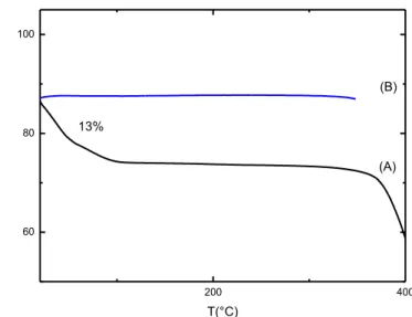
has been quantified by thermogravimetric analysis (Figure 2. 10). Measurements confirm that the guest is selectively adsorbed by the PPO phase of the PPO/s-PS aerogel (13%), infact in δ s-PS aerogel the amount of adsorbed guest is less than 0, 5%. Then, a CCl4 selective uptake from PPO in the PPO/s-PS aerogels is effectively present. In the same conditions, the CCl4 uptake
from the PPO/s-PS - 90/10wt% aerogel with crystalline PPO (of Figure 2.5E), exhibiting surface area higher than for 50/50 aerogels (Table 2), is close to 19wt%.
Figure 2. 10 Thermogravimetric measurements of CCl4 amount in s-PS/PPO(χPPO=0. 5) Cpol=20% (A) and δ s-PS aerogel (Cpol=1%)(B) after
equilibrium CCl4 (10ppm) sorption from its aqueos 10ppm solutions. It is worth adding that, with respect to films, the macropores of the aerogels not only result in an increase in the guest sorption
200 400 60 80 100 (B) % w /w T(°C) 13% (A)
57
kinetics but can also increase the uptake values for molecules presenting a poor solubility in the polymer amorphous phase. The CCl4 uptake in PPO films has been also investigated and
FTIR spectra collected before and after immersion of a PPO film in a 10ppm aqueous solutions is reported in Figure 2.11.
58
Figure 2. 11 FTIR spectra of semicrystalline PPO film (A) amorphous PPO film (B) before (black curves) and after (red curves) equilibrium CCl4 sorption
from its aqueos 10ppm solutions.
In similar conditions the CCl4 uptake from the film samples for dilute aqueous solutions is less than 1%, also for this reason the achievement of monolithic aerogels that include the crystalline pores of both PPO and s-PS is a very important result.
As mentioned above the sorption measurements have been also carried out with DCE dilute aqueous solutions for s-PS/PPO aerogels with χPPO=0. 50 (Cpol=20%). Figure 2.12 shows the
FTIR spectra for s-PS/PPO aerogel χPPO=0. 50 (Cpol=20%) 700 720 740 760 780 800 820 (B) Ab sor bance (a. u. ) Wavenumber (cm-1) (A) CCl4
59
before (B) and after (C) equilibrium DCE (blue curve) sorption from a 10 ppm aqueos solutions. Spectral subtraction is also shown (C-B).
Figure 2. 12 FTIR spectra of DCE with gauche and trans peaks (A) s-PS/PPO aerogel (χPPO=0. 5) Cpol=20% before (B) and after (C) equilibrium DCE sorption from its aqueos 10ppm solutions. The black curve shows the
subtraction between (C-B)
In figure 2.12, gauche (G) and trans peaks (T) of DCE are shown 19e. After immersion only peak of trans conformer is
observed (1235 cm-1 ) as evidenced by spectral subtraction
1220 1240 1260 1280 1300 (C- B) (C) (B)
T
Abs orbance (a.u. ) Wavenumber cm-1G
1235 (A)60
(Figure 2.12 C-B); it means that DCE is selectively adsorbed by δ s-PS phase of the s-PS-PPO aerogel. 19e
The amount of DCE has been quantified by thermogravimetric measurements, and is equal to 2. 5% while for δ s-PS aerogel (Cpol=1%) the DCE uptake from dilute aqueous solutions (10 ppm) is 5 %. 19b
So, in the same condition, the DCE is selectively adsorbed form δ s-PS in s-PS/PPO aerogel, while CCl4 is adsorbed quickly and
in large quantities only from PPO in s-PS/PPO aerogel with χPPO=0. 50 and χPPO=0. 90 (Cpol=20%).
This inverse selectivity trend is outlined in Fig 2. 13.
It's important to specify that for the gravimetric sorption isotherm at 35°C and at a pressure of 0. 1 P/P0, we observe an higher CCl4 uptake (green curve) than from the aqueous 10 ppm
solution, also for the pure δ s-PS. Much likely this is caused by the formation of a hydrated species of carbon tetrachloride in the aqueous solution, 29which increases the guest size thus
61
Figure 2. 13. Percentage uptake vs PPO increasing concentration, from : DCE diluted aqueous solutions (10 ppm)( black curve), CCl4 diluted aqueous
solutions (10 ppm)( red curve). The magenta curve is the sorption isotherms at 35 ° C and at a pressure of 0. 01 P/P0 CCl4 and the green curve is the
sorption isotherms at 35 ° C and at a pressure of 0. 1 P/P0 CCl4.
0 10 20 30 40 50 60 70 80 90 100 0 5 10 15 20 25 30 35 40 CCl 4 CCl4 DCE PPO U p ta ke % s-PS CCl4