The BioRobotics Institute – Scuola Superiore Sant’Anna
PhD Programme in BioRobotics
XXIX Doctoral Cycle
Smart magnetic microsystems for
targeted therapy
June 21
st, 2017
PhD Candidate
Veronica Iacovacci
Tutor
Dr. Leonardo Ricotti
Supervisor
Table of contents
Abstract...1
List of Tables...4
List of Figures ...5
List of Abbreviations...10
1. Motivations and Background ...12
1.1 Motivations ...12
1.2 Therapeutic index and targeted therapy ...13
1.3 Microrobotics for medical applications...17
1.4 Triggerable therapeutic micro and nanosystems...22
1.5 Limitations and open challenges...24
2. Polydimethylsiloxane films doped with NdFeB powder: fabrication and characterization 27 2.1 Magnetic materials for MEMS and microrobtics ...27
2.2 Composite magnetic film fabrication ...30
2.3 Film Magnetic characterization...33
2.5 Composite film surface treatment towards biomedical applications ...38
2.6 Discussion...44
2.7 Case Study 1: Cell magnetic manipulation platform towards personalized medicine applications ...45
2.8 Case Study 2: Endovascular catheter for drug-loaded magnetic thin films release...49
3. Magnetic bi-component milli-robot for targeted drug delivery...52
3.1 Sub-millimetric untethered systems for targeted therapy and magnetic independent control strategies ...52
3.2 System design: general considerations and operation concept...53
3.3 System design and modeling...56
3.4 Drug-loaded hydrogel ...60
3.5 Polymeric shell and robot fabrication ...64
3. 6 Locomotion and docking tests ...67
3.7 Drug release tests...68
3.8 In vitro tests on cancer cells ...70
3.9 Perspectives and future work ...73
4. Thermoresponsive magnetic microrobots: imaging and drug delivery towards medical applications ...75
4.2 Shape switching and self-folding microstructures ...77
4.3 Microrobots imaging:towards in vivo applications ...79
4.4 Therapeutic platform overview...79
4.5 Microrobots fabrication: getting down the scale...81
4.6 Drug delivery: the role of shape and dimensions...85
4.7 Microrobot imaging: looking for a proper imaging modality...90
4.8 Radiocompound embedding...94
4.9 SPECT in vitro and ex vivo imaging ...96
4.10 Perspectives and future work ...100
5. Magnetic retrieval of theranostic nanoagents...103
5.1 Tumor targeting and nanomedicine...103
5.2 Are magnetic nanoparticles safe? ...104
5.3 Strategies to overcome long-term adverse effects...106
5.4 Devised therapeutic strategy and system overview ...108
5.5 Magnetic capture modeling and design considerations ...111
5.6 FEM Simulations...114
5.7 Magnetic module design...118
5.8 In vitro validation ...121
5.9 Perspectives and future work ...125
6. Conclusion and future perspectives...128
Appendix A: Magnetic Materials...133
Appendix B: SPECT imaging...137
References ...140
Scientific production ...151
Papers on ISI Journals...151
Papers on International peer-reviewed Conferences ...151
Book Chapters ...153
Abstract
Recent advancements in diagnostics have led to early stage detection of many pathologies, potentially paving the way to an earlier and more effective treatment of several life-threatening diseases. Despite significant steps ahead in the past decades both in the field of minimally invasive surgery and in pharmacology, with the development of more and more sophisticated instrumentation and drug formulations, there is still a significant gap between diagnosis and therapy, at present.
Merging competencies derived from robotics, bioengineering and materials science can help in moving forward in this research endeavor, aiming at filling such gap by developing enabling technologies, components and platforms capable of treating many pathologies in the human body, even in hard-to-reach areas.
In this framework, an ambitious dream is to develop therapeutic strategies able to treat pathologies that are nowadays incurable, but also to improve existing treatments, making them more efficient and reducing their burden to healthy tissues, thus enhancing their therapeutic index.
This Thesis explores novel miniaturized systems that aim to overcome some of the limitations featuring current therapeutic paradigms, based on systemic administration, as well as traditionally proposed nanomedicine strategies that suffer from low controllability. To this aim, the main focus is on solutions at the milli- and the micro-scale, which potentially allow to access all human body districts by exploiting the wide network of natural body lumens and endoluminal accesses. Furthermore, a specific attention has been paid to systems controllable through magnetic fields, a paradigm that has been exploited to enhance microsystems controllability when on-board actuation technologies lack behind. The Thesis is organized in six Chapters and two Appendices (Figure 1). Each Chapter deals with the development of a novel technological tool or miniaturized device. Each reported system is not an evolution of the one reported in the previous Chapter, but it is possible anyhow to identify a fil rouge among them, thus considering each Chapter a step forward in the pathway towards more efficient
medical miniaturized systems, thus towards filling the gap among diagnostics and therapy.
Chapter 1 reports the motivation of the whole thesis and a general background concerning therapeutic strategies, microrobotics and triggerable systems for medical applications. It also aims at sketching limitations and open challenges in the mentioned domains. Chapter 2 deals with the fabrication, the magnetic and morphological characterization and the biological assessment of novel magnetic composite materials, developed in the form of thin films. They may enable to overcome the limitations of current magnetic microsystems and they could be useful for the development of a variety of Micro Electro-Mechanical Systems (MEMS) and biomedical microdevices. Appendix A adds theoretical considerations on magnetic materials properties and characterization, thus supporting the design considerations reported in Chapter 2 and all over the thesis. Chapters 3 and 4 report the design, fabrication and testing of a milli- and microrobot, respectively, devised for targeted drug delivery in the human body. The system described in Chapter 3 is a triggerable bi-component magnetic millirobot for targeted drug delivery, devised for operation in relatively high diameter body canals and based on the superposition of different magnetic effects enabling both its controlled locomotion and the activation of the drug release mechanism. In Chapter 4, a shape-switching microrobot responsive to magnetic fields and to near infrared radiation is reported. Fabrication and controlled drug delivery modulated by shape changes were validated at different scales. Chapter 4 also deals with a challenge that typically affects microrobots for medical applications, namely how to perform a proper in vivo imaging. To this aim, proper microrobot structure modifications and Single photon emission computed tomography (SPECT) imaging (whose working principles are clarified in Appendix B) are reported both in vitro and ex
vivo.
In all cases, the outcomes of targeted therapy strategies strongly depend either on the accumulation efficiency in the target region and on the effective amount of therapy delivered, thanks for example to triggering mechanisms. Tumor treatment, for example, strongly depends on therapeutics dose or on drug formulation efficiency. In both cases, a never ending struggle between the desire to concentrate
toxic doses of therapeutics in the site of interest and the need to avoid undesired side effects on healthy tissues arises.
The possibility to retrieve from the body the unused agents not contributing to therapy (but that would just eventually produce side effects), appears as the holy grail of cancer treatment. In this framework, Chapter 5 reports a novel intravascular microdevice able to efficiently retrieve magnetic therapeutic nanovectors not contributing to therapy from the bloodstream. The device concept is described and the system design and in vitro testing are reported.
Finally, Chapter 6 sketches out the conclusions of this study and highlights future perspectives, by describing possible routes and strategies to address scientific and medical issues still hampering the wide adoption of micro and nanosystems in the clinical practice.
List of Tables
Table I Magnetic parameters of films with different ndfeb powder concentrations...34
Table II Density of robot constitutive components...60
Table III Hydrogel layers thickness at varying of 2D side dimensions ...84
List of Figures
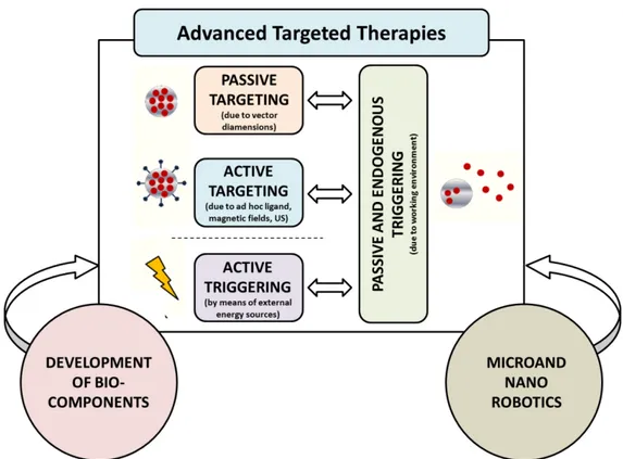
Figure 1. Thesis organization and workflow...3 Figure 1. 1 Building blocks of advanced targeted therapies, included possible contaminations due to interdisciplinary efforts involving the fields of micro/nanorobotics and biotechnology (Adapted from Ricotti et al. 20154). ...17
Figure 1. 2 Overview of wireless actuation and stimulation strategies at the microscale...18 Figure 1. 3 Overview of different micro/nanorobots locomotion strategies actuated by means of external powering or on board motors. (A) Artificial bacteria flagella41. (B) Helical tail
locomotion by means of rotating magnetic fields29. (C) Expansion and vaporization of
perfluorocarbon emulsion droplets produced by ultrasound35. (D) Self-acoustophoretic robot37.
(E) Light-driven microrobot42. (F) Self-diffusiophoresis mechanism43. (G) Functionalized
magnetotactic bacteria44. (H) Theranostic bacteria-based microrobot45. (Adapted from Ricotti
et al. 20154)...20
Figure 2. 1 SEM images of NdFeB powder before (A) and after (B) the milling process...30 Figure 2. 2 Composite film fabrication procedure. ...31 Figure 2. 3 Hirox microscope images of a bare PDMS film and of composite samples with different NdFeB powder concentrations. ...32 Figure 2. 4 (A) Composite microrobots microfabrication process. (B) Scanning Electron
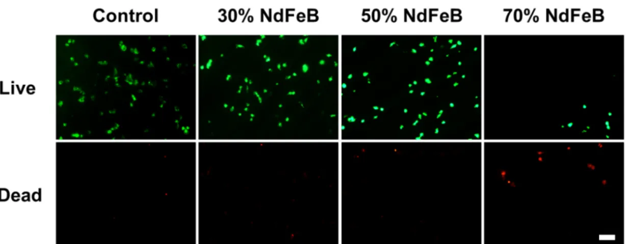
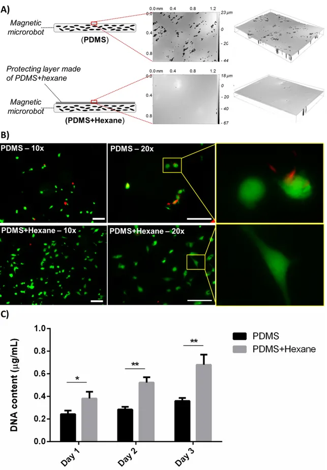
Microscope (SEM) image of the microfabricated composite material-based microrobot, obtained by using a PVA sacrificial mold...33 Figure 2. 5 (A) Typical magnetization curve with main parameters pointed;. (B) Magnetization curves of films provided with different NdFeB powder concentrations. (C-E) Trends of residual magnetization Mr, magnetic susceptibility χ and saturation magnetization Ms, respectively. For each curve, both experimental points and linear fittings, together with the correspondent equations, are reported. ...34 Figure 2. 6 Force diagram for a thin film-based magnetic microrobot. T, Fm, Fp, Fd, W, Tm, Fpm and TD are the surface tension, the magnetic force, the net pressure force, the drag force, the weight force, the magnetic torque, the magnetic force generated by permanent magnets and the drag torque, respectively. The parameters ε and α are the filling and the contact angles, respectively. ...35 Figure 2. 7 (A) Electromagnetic navigation setup and detail of the workspace with a manually-shaped microrobot (PDMS – 50%NdFeB powder) during navigation tasks. (B) Navigation velocity versus magnetic powder concentration. Ten samples were tested for each film type and three navigation tasks were performed for each sample. **=p<0.01. ...38 Figure 2. 8 T24 cell viability on the different film types. Live cells are shown in green, dead cells are shown in red. Scale bar = 100 μm...40 Figure 2. 9 Depiction of bare magnetic films (70% of NdFeB powder content) and of similar samples, coated with 10 polyelectrolyte bilayers. Fluorescence images at different
magnifications, taken 24 h after cell seeding, show live cancer cells (in green) and dead/necrotic cancer cells (in red) on the uncoated and on the polyelectrolyte-coated
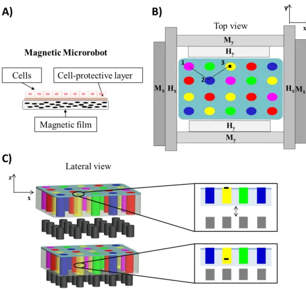
Figure 2. 10 (A) Depiction of the different sample types tested and surface morphology, obtained through optical profilometry; (B) cell viability and shape on the different sample types: live cells are shown in green, dead/necrotic cells are shown in red. Scale bars = 100 µm. (C) Evolution of DNA content over time, related to cell proliferation ability, on the different sample types. *=p<0.05, **=p<0.01. ...43 Figure 2. 11 Concept of the proposed platform: thin film-based magnetic microrobot acting as cell carrier (A); multiwell chip placed in the workspace of a magnetic apparatus including a combination of Helmholtz (Hx, Hy) and Maxwell (Mx, My) coils and an array of permanent magnets (B and C). The navigation of the film (small black rectangle) towards different spots (different colors represent different drugs) is depicted (B), as well as the immersion procedure (C): once the film reaches a desired drug spot, cells are exposed to the drug by immersing the film, through the array of permanent magnets that approach the chip...47 Figure 2. 12 (A) Image of the chip produced in PDMS before the hydrogel is added (B)
Representative images (lateral view) of the microrobot immersed in the liquid solution thanks to the attraction produced by the immersion system. ...48 Figure 2. 13 Depiction of the magnetic thin film delivery (A) and retrieval (B) catheters. (C) Representation of the proposed targeted antirestenotic drug release procedure; (D) picture of the proposed catheter prototypes...51 Figure 3. 1 Bi-component robot design and constitutive elements...54 Figure 3. 2 (A) Eligible target district; (B) schematization of bi-component system injection towards the target region; (C) schematic representation of the devised targeted therapy procedure phases...55 Figure 3. 3 Compression tests have been carried out by means of an Instron machine (Instron 4464). Several tests were performed for each hydrogel composition (gelatin concentration fixed at 1% w/v and agar concentration varying between 0.25% and 4%) both in PBS and air. The histogram reports the Young compression modulus mean values extracted from the stress-strain curves. ...62 Figure 3. 4 Abaqus FEM simulation results. (A) Hydrogel deformation produced by magnetic attraction force as a function of agar concentration. (B) Distribution of stress on the chosen hydrogel. (C) Deformation of the 0.25% agar-1% gelatin hydrogel after squeezing (blue and red lines refer to the initial and the final surface of the hydrogel, respectively). ...63 Figure 3. 5 Comparison in terms of Young compression modulus between 0.25% agar – 1% gelatin hydrogels with and without doxorubicin embedded and while testing their behavior both in Air and PBS. *=p<0.05...64 Figure 3. 6 Robot fabrication procedure. (A) NdFeB powders are added to the PDMS polymeric solution. (B) The compound is poured into the molds. (C) Permanent magnet causes powders to accumulate at the robot’s head. After demolding, the carrier components with embedded powder are permanently magnetized by means of an MRI scanner. (D) The piston and the carrier are assembled, by also embedding a spherical permanent magnet. (E) The hydrogel is injected into the carrier. ...65 Figure 3. 7 Robot prototypes: (A) carrier without NdFeB powders on its tips; (B) piston
prototype; (C) carrier with NdFeB powder embedded and piston prototype; (D) carrier and piston in the docked configuration. ...66
Figure 3. 8 (A) Drug-loaded agar-gelatin hydrogel. (B) Procedure of drug-loaded hydrogel injection into the carrier. (C) Carrier prototype with drug-loaded hydrogel embedded. (D) Docked configuration, with the hydrogel squeezed. ...67 Figure 3. 9 Experimental validation of navigation and docking. A magnetic field of 5.2 mT and a magnetic field gradient of 0.05 T/m were generated by means of a permanent magnet placed below the workspace. (A) The carrier is kept fixed in the target position and the piston is injected into the PDMS channel. (B) The piston is oriented for navigation to the target. (C) Piston path towards the carrier. (D) Docking of the carrier and the piston. Scale bar: 5 mm. ...68 Figure 3. 10 (A) Doxorubicin calibration curve correlating the measured absorbance values with the doxorubicin amount dissolved in water. (B) Amount of drug released in 20 min by docked robots and controls and expanded view of the release curve, to better evaluate the amount of drug released from the undocked robots; (C) Overall drug quantity released in 20 min from the two sample types (mean values ± standard deviations). *=p<0.05. ...70 Figure 3. 11 Results of in vitro tests, performed on a human urinary bladder carcinoma cell line (T24). “Negative control” refers to non treated cells; “Undocked robot” refers to cells treated by immersing the carrier in the culture well, without squeezing it, for 20 min; “Docked robot” refers to cells treated by immersing the carrier, docked to the piston, in the culture well for 20 min; “Positive control” refers to cells treated with 10 μg/mL doxorubicin, directly dispersed in the culture medium. (A) Bright field and fluorescence images for the different sample types, 24 h after the treatment (nuclei in blue, ROS production in red). (B) DNA content (related to cancer cell proliferation rate) for the different sample types, 72 h after the treatment.
**=p<0.01. ...73 Figure 4. 1 Overview of the shape switching hydrogel bilayer based microrobot. (A) bilayer structure; (B) shape switching mechanism depiction. ...81 Figure 4. 2 Microrobot fabrication protocol schematization and phases. ...83 Figure 4. 3 Hirox microscope images of 1.5 – 1 and 0.5 mm microrobots in the folded and unfolded configuration. Scale bar 500 µm...84 Figure 4. 4 Different phases of the NIR induced shape transition from the folded to the
unfolded configuration for a 0.5 mm microrobot...85 Figure 4. 5 Overview of the proposed microrobot: (A) depiction of the bilayer structure; (B) representation of the microrobot shape transition due to thermal stimuli. ...87 Figure 4. 6 Doxorubicin release profile for a single 3 mm side microrobot in the folded and unfolded configuration. Overall release with respect to the embedded doxorubicin amount is reported for each configuration...88 Figure 4. 7 Doxorubicin release profile for a single 1.5 mm side microrobot in the folded and unfolded configuration. Overall release with respect to the embedded doxorubicin amount is reported for each configuration...88 Figure 4. 8 Doxorubicin release profile for a single 1 mm side microrobot in the folded and unfolded configuration. Overall release with respect to the embedded doxorubicin amount is reported for each configuration...89 Figure 4. 9 Doxorubicin release profile for a single 0.5 mm side microrobot in the folded and unfolded configuration. Overall release with respect to the embedded doxorubicin amount is reported for each configuration...89 Figure 4. 10 Doxorubicin release in the unfolded configuration across the four dimensions, normalized to the volume of the drug loaded hydrogel layer. ...90
Figure 4. 11 (A) Ziehm Imaging C-Arm fluoroscope; (B) fluoroscopy in vitro images of PEGDA samples loaded with x-ray contrast agents...92 Figure 4. 12 (A) US imaging setup overview; (B) PEGDA samples with different amount of US contrast agent medium embedded in the polymeric structure US images. ...93 Figure 4. 13 US images of two 3 mm microrobots embedded in the described tissue mimicking phantom. (A) microrobots without any US contrast agent; (B) microrobots with SONOVue embedded at concentration equal to 50 % V/V in the PEGDA layer. Microrobots are circled in red...93 Figure 4. 14 Microrobot residual activity after 2 h of incubation at room temperature for different radiocompounds and microrobots dimension...96 Figure 4. 15 SPECT imaging of 3mm, 1.5 mm, 1 mm and 0.5 mm microrobots embedding 99mTc- radionuclide (A) and 99mTc-zinc colloid (B). In both the images the same color scale has
been employed and the measured single robot activity are reported. ...98 Figure 4. 16 CT and SPECT imaging of a single microrobot at different scales. For each
microrobot dimension, CT and SPECT images projections along the three main cutting planes are reported...98 Figure 4. 17In vitro 3 mm microrobot SPECT images in the folded (A) and unfolded (B)
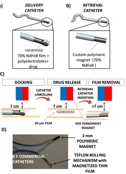
configurations along the three main cutting planes. ...99 Figure 4. 18 Ex vivo imaging of radiolabelled microrobots subcutaneously injected in mice ..100 Figure 5. 1 (A) Devised therapeutic procedure schematization; (B) Detailed view of unused therapeutic vectors retrieval in a body district characterized by terminal circulation. ...109 Figure 5. 2 Depiction of a liver with a tumor mass and of the access through the injection and retrieval catheter. ...110 Figure 5. 3 Intravascular device schematization in which the constitutive blocks are described.
...110 Figure 5. 4 (A)Magnetic module 2D representation in Comsol Multiphysics environment; (B) zoomed view of a portion of the magnetic module in which the internal and the external series of permanent magnets are indicated; (C-E) Fluidic velocity, magnetic field and particle
trajectories in the proposed magnetic module. (F) FEM simulations results in terms of capture efficiency when considering a single magnet, placed either centrally or externally; Magnetic capture efficiency when varying magnet number (G), grouping (H) or nanoparticle diameter (I).
...118 Figure 5. 5 Magnetic module schematization. (A-B) External series of magnets and (C-D) internal series of magnets. In both the cases 2D and 3D view are provided.(E) Graphical
representation of the magnetic module embedded in the intravascular device with all the main components indicated (external magnets are cut in section to enable a clearer understanding even of the inner structure)...120 Figure 5. 6 (A) Retrieval catheter prototype with the mail units pointed out; (B) Retrieval catheter with inserted Seldinger guidewire; (C) Magnetic module prototype; (D) detail of Seldinger guidewire passing across the magnetic module. ...121 Figure 5. 7 In vitro validation fluidic circuit schematization...122 Figure 5. 8 Comparison among theoretical (calculated through FEM) and experimental capture efficiency when considering the scaled and the final prototype. ...123 Figure 5. 9 Comparison among theoretical (calculated through FEM) and experimental capture efficiency when considering 500 and 250 nm magnetic nanoparticles. ...124
Figure 5. 10 Retrieval efficiency when performing multiple consecutive tests on the same prototype. Reported results refer to 500 nm (A) and 250 nm (B) magnetic nanoparticles...125
List of Abbreviations
AAM = AcrylamideAGM = Alternating Gradient Magnetometer CNS = Central Nervous System
CT = Computed Tomography DES = Drug-eluting stents
DMPA = 2,2-dimethoxy-2 phenylacetophenone DNA = Deoxiribonucleic acid
EL = Ethyl Lactate
EPR = Enhanced Permeation and Retention FBS = Fetal Bovine Serum
FDA = Food and Drug Administration FEM = Finite Element Method
FEP = Fluorinated ethylene propylene GNP = Gold Nanoparticle
ICP-MS = Inductively Coupled Plasma Mass Spectrometry LbL = Layer-by-Layer
LCST = Lower Critical Solution Temperature LOC = Lab-on-a-chip
MEMS = Microelectromechanical Systems MNP = Magnetic Nanoparticle
MRI = Magnetic Resonance Imaging NdFeB = Neodimium Iron Boron NIPAAM = N-isopropylacrylamide NIR = Near infrared
NP = Nanoparticle
PBS = Phosphate Buffered Saline PDMS = Polydimethylsiloxane
PEGDA = Poly(ethylene glycol) diacrylate PET = Positron Emission Tomography PTM = photomultiplier tube
PVA = polyvinyl alcohol ROS = reactive oxygen species SEM = Scanning Electron Microscope
SPECT = Single Photon Emission Computed Tomography SPION = Superparamagnetic Iron Oxide Nanoparticle SQUID = Superconducting Quantum Interference Device TDD = Targeted Drug Delivery
TI = Therapeutic Index US = Ultrasound
VSM = Vibrating Sample Magnetometer VSMC = Vascular Smooth Muscle Cell
1. Motivations and Background
1.1 MotivationsRecent advancements in diagnostics have led to early stage detection of many pathologies, potentially paving the way to early treatment and to a more efficient fighting of many life threatening diseases. Despite great advancements in the past decades, both in the field of minimally invasive surgery1 and in pharmacology, there is still a significant gap between diagnosis and therapy.
Cancer is the third cause for death in the world (after cardiovascular diseases and infections), with approximately 14 million new cases and 8.2 million cancer-related deaths per year, with a growing trend2. Therapeutic approaches for cancer range from surgical excision, to radiotherapy, ablation therapy (e.g. by focused ultrasound) up to solutions based on pharmacological agents. The chemotherapeutic approach via systemic administration is the most commonly employed strategy, sometimes in conjunction with radiotherapy and surgical resection. The responses associated with such therapeutic regime are often partial, short-term and unpredictable3, due to low compound solubility, toxicity to healthy cells and scarce accumulation at the tumor site.
The development of targeted therapy strategies, potentially enables to penetrate into the hard-to-reach areas of the human body and to selectively perform therapy in a controllable fashion. This appears as the holy grail in the treatment of cancer and other life-threatening pathologies4 and would not only enable the treatment of currently incurable pathologies, but would also imply an improvement of existing treatments, making them more efficient and reducing their burden to healthy tissues, thus enhancing their therapeutic index.
A merging of competencies coming from robotics, bioengineering, biotechnology and material science should be pursued towards this objective.
Many results have been accomplished in the field of microrobotics towards the development of microsystems able to navigate and perform manipulation in a highly controllable way in 3D environments. Translation of these approaches to medical applications is desirable, yet not straightforward5,6, due to the need to
combine controllability and biocompatibility, to enable in vivo tracking of the procedure and to endow microsystems with efficient therapy delivery mechanisms.
On the other hand, huge research efforts have been devoted towards the development of the so called Ehrlich’s “Magic Bullet”7. The fields of nanomedicine and targeted therapy have been rapidly growing both in terms of public awareness on the theme and of scientific literature production8,9. However, in most cases, current paradigms still remain strictly adherent to a traditional route, simply based on advancements concerning nanocarriers chemical formulation/functionalization, and rarely in enhancing controllability in target reaching and on demand therapy performance.
In this framework, microengineering and microrobotics could provide the added value of controllability for nanotechnology and drug delivery systems, in order to employ the resulting microsystems in real medical applications, as promising tools for highly efficient therapeutic strategies. The development of enabling technologies, components and platforms capable of treating many pathologies in the human body, even in hard-to-reach areas, while featured by clinical acceptability and safety, is thus requested yet extremely challenging.
In the following Sections, after defining and classifying targeted therapy systems, an overview of microrobotic systems proposed so far, will be provided with a main focus on their controlled locomotion strategies. An overview of triggerable therapeutic systems will be provided as well with a particular focus on on-demand drug delivery systems. These would represent the starting point and the building blocks towards the development of highly efficient therapeutic platforms based on micro- and nanosystems.
1.2 Therapeutic index and targeted therapy
When dealing with therapeutic strategies and when evaluating their efficiency, a key parameter to be considered is the Therapeutic Index (TI), defined as the ratio between the drug dose that produces toxicity in 50% of the population (TD50) and
the minimum drug dose that is effective for the desired therapy for 50% of the population (ED50)4: (1.1) 50 50 ED TD TI
A higher TI can be achieved by increasing the drug dose that produce undesired toxicity or by reducing that for effective therapy. A proper drug targeting produces simultaneously both effects, thus significantly increasing the TI of a specific compound.
In this scenario, targeted therapy in selected areas of the human body represents the Holy Grail for the effective treatment of many pathologies, including cancer. A certain level of targeting is already pursued by minimally invasive surgical approaches10 or by robotics assistance for radiotherapy (as in the CyberKnife system - http://www.cyberknife.com/), but chemotherapeutics are normally delivered by intravenous route - or by arterial route in some specific cases - without any real targeting strategy.
When dealing with targeted procedures, the challenging aim of achieving a “magic bullet” (a drug that selectively attaches to diseased cells but non-toxic to healthy ones), already postulated by Paul Ehrlich almost one century ago7,11, arises. According to the definition of the U.S. National Institutes of Health (NIH), a targeted therapy is “a type of treatment that uses drugs or other substances to identify and attack specific types of cancer cells with less harm to normal cells”. Although cancer represents the main focus (being also embedded in the NIH definition), targeted therapies can also find important applications in the treatment of many non-cancer related diseases, from cardiovascular, to infectious and chronic inflammatory ones. The possibility to perform an efficient targeting enables to direct higher amount of therapy into the lesion, to produce higher treatment efficiency and to employ highly effective pharmaceutical formulations (e.g. cisplatinum, doxorubicin, etc.), which are currently not employed in the clinical practice due to the severe side effects produced on healthy tissues. Doxorubicin for example, despite the high efficacy in treating tumors, produced
side effects such as heart failure for doses above 360 mg12, in addition to pain, nausea, vomiting myelosuppression and gastrointestinal disturbances occurring even for standard doses in the range 50-75 mg13.
Some targeted chemotherapy strategies have been proposed for specific body districts such as the liver or the pancreas: they are based on the direct injection of drugs into the target organ, usually through an arterial access and possibly relying on the occlusion of specific blood vessels such as in the case of chemoembolization14-16.
Many research efforts have been undertaken in order to find effective strategies for localizing therapeutics means in the lesion site.
The role of nanomedicine and biomedicine in this targeting process has been extremely relevant. In the last two decades, a broad range of nanomaterials have been developed for targeted therapies. Their unique characteristics, such as large surface areas, structural properties and long circulation time in blood (compared with small drug molecules) have allowed to increase the TI of anti-cancer drugs17,18. In addition, incorporation into nanosystems allows to reintroduce into clinical practice drugs that were no longer used, due to poor dispersion ability and suboptimal pharmacokinetic profiles19.
The first objective of nanomedicine (defined as the design and development of therapeutic agents with diameters ranging from 1 nm to 1 µm) has concerned the development of passive nanocarriers. At the beginning, these systems mainly served as “drug containers” able to efficiently disperse therapeutic molecules in their structures, to assure a favorable blood half-life and to minimize the immune system response17. They mostly relied on passive drug targeting, consisting of a preferential accumulation of nanocarriers at the tumor site, due to the enhanced permeation and retention (EPR) effect20. However, most of the carriers developed to this purpose show physio-chemical properties that allow for versatile modification possibilities. Thus, active targeting emerged, by employing specific affinity ligands able to recognize and bind to cancer cells or to the angiogenic endothelium surrounding the tumor, thus facilitating drug endocytosis21. Active targeting can be pursued even by employing external energy sources (e.g.
magnetic fields, ultrasound, etc.) enabling the selected accumulation at the lesion site.
The described nanomedicine paradigm recently evolved towards responsive nanosystems, to be triggered by means of altered microenvironment conditions or by remote energy sources. This opened the way to more flexible drug delivery strategies, based on an internal trigger (e.g. a smart material affected by endogenous pH or temperature changes) or, more interestingly, on an external one, provided by an operator (see section 1.4 for a more detailed description of triggerable targeted therapy systems) (Figure 1. 1).
It is worth mentioning that passive triggering is a “transversal” mechanism, which is always present in targeted therapies. Indeed, it allows drugs to be released from the carrier and to become available for the cells. In the case of passive targeting, the extracellular conditions normally act as a trigger. In the case of active targeting, the altered chemo-physical conditions at intracellular level normally constitute the trigger for drug release. In the case of active triggering, passive triggering mechanisms are still on the stage, but they are undesired as they lower the efficiency of remote drug release control. Thus, chemical strategies are needed to provide the nanocarriers with a high resistance to physiological environmental shifts, making them responsive only to external triggers, activated by an operator. All the above mentioned research trends are strongly grounded on very specific disciplines, such as organic chemistry, materials science and pharmaceutics, in addition to micro/nanotechnologies. In parallel, the last decades were also characterized by the thrive of highly interdisciplinary research lines in which micro and nanotechnologies were associated with robotics, computer science and biotechnologies. These efforts aimed at embedding smart bio-components and at developing miniaturized controllable devices (micro and nanorobots) able to perform operations down to the nanoscale22,23. This represents an ambitious objective that would have clear benefits for the treatment of many pathologies.
Figure 1. 1 Building blocks of advanced targeted therapies, included possible contaminations due to interdisciplinary
efforts involving the fields of micro/nanorobotics and biotechnology (Adapted from Ricotti et al. 20154).
1.3 Microrobotics for medical applications
Designing miniaturized and versatile robots would allow controlled access to the hard-to-reach-areas of the human body, leading to new procedures down to the cellular level and offering localized diagnosis and treatment with greater precision and efficiency. The development of micro and nanoscale robotic systems holds considerable promise for enhancing the treatment of a wide variety of diseases and disorders. Microrobots have been proposed for a wide variety of biomedical applications ranging from targeted drug delivery, targeted therapy, biopsy, enhanced diagnostics and sensing5,6.
It is worth conceiving these tiny systems as complex platforms, whose features strongly depend on the working environment and on the procedure to be performed.
The robot normally acts as a carrier for the therapeutic agent. To enable its action, a sensing/localization system and a control strategy, required both for robot locomotion and therapy triggering, must be considered.
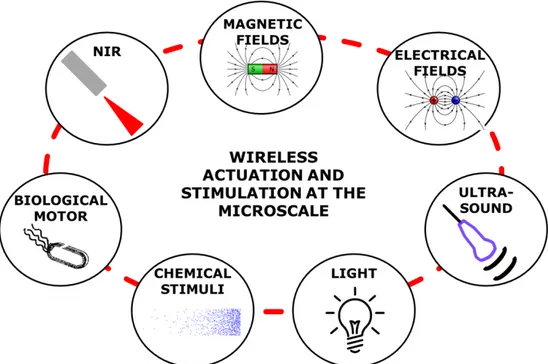
In the past few years, major technical and scientific advancements in the fields of material science, microfabrication and control engineering have enabled the development of sophisticate and efficient microsystems whose translation to real applications, both in laboratory and clinical practice, is getting closer and closer. One of the greatest challenge when designing a smart microsystem or a microrobot is to enable the performance of a specific function in a controllable way. Due to dimensional constrains, exploiting traditional actuation and control strategies in these microsystems is pretty impossible. This implies endowing the structure itself with on-board “intelligence” which could be provided by the constitutive material and/or by a specific design. Many strategies have been proposed so far in the literature for microsystems wireless stimulation and actuation based for example on magnetic/electrical fields, light, ultrasound, or embedding of biological components (Figure 1. 2).
Figure 1. 2 Overview of wireless actuation and stimulation strategies at the microscale.
When thinking about locomotion of microrobots inside the human body, we refer to the ability of “swimming” through a dense network of low caliber fluid-filled channels, including but not limited to the cardiovascular system. In such environment, Reynolds number (Re) is lower than one, thus making impossible
certain motion strategies, typically performed at the macro-scale. Reciprocal motion, for example, results in a null displacement24 and surface and capillary forces are more relevant than volumetric ones25,26. This compels to abandon the traditional paradigm sensor-actuator-controller that normally dominates the robotics field at larger scales and to look for new actuation strategies, efficient at low Re numbers and compatible with the narrow space available.
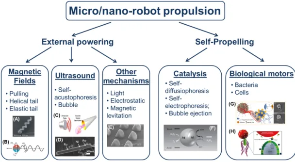
In most cases micro/nanorobots are provided with the capability to convert energy into motion and thus to swim in a controlled or semi-controlled way towards the target. This can be achieved by exploiting wireless powering sources or self-propelling strategies (on-board motors) (Figure 1. 3).
The most exploited wireless powering strategy employs magnetic fields that can be easily produced by means of a Magnetic Resonance Imaging (MRI) scanner27 or a dedicated electromagnetic setup28. Magnetic fields enable different locomotion strategies, ranging from the simple microrobot pulling to the more bioinspired helical29 or elastic tail propulsion30. The main advantage of magnetic locomotion lies in the possibility to wirelessly control a robot in a three-dimensional space and with multiple degrees of freedom, thus allowing it to follow really complicated paths, if needed, to reach the target region31,32. Moreover magnetic fields can cross body tissues in a safe way and without attenuation (except the one due to the distance from the source). However, magnetic control calls for dedicated bulky external magnet setups and complex control algorithms. In addition, to establish a proper magnetic coupling, micro-objects should be provided with suitable magnetic properties ensuring a proper control; this is not straightforward at the microscale, especially without affecting biocompatibility.
Ultrasound (US) has been also proposed as a possible strategy for microrobots actuation. In particular, self-acoustophoresis mechanisms based on the formation of local pressure gradients on the concave end of a nanowire33 or kinetic energy production through the expansion and vaporization of perfluorocarbon emulsion droplets34, can be exploited to provide wireless powering and to propel medical microrobots35. In the case of self-acoustophoresis, however, robots move on a plane, thus making quite difficult to translate this technology into in vivo applications. In the case of expansion and vaporization of droplets, the need of a
specific fuel (droplets) for the actuation mechanism makes these systems able to achieve only really short strokes. Recently, small-amplitude oscillation of a flagellum-like flexible tail in standing and, more importantly, in traveling acoustic waves was reported36. In all cases, US-based actuation enables robots propulsion but not their orientation; magnetic fields are thus usually employed in synergy with US to orient and steer the robots37.
Further actuation strategies, such as light38, magnetic levitation39 or electrostatic forces40, have been recently investigated, but their employment in medical applications is not straightforward, due to the inability to produce 3D locomotion or to the scarce translability of the external control system and/or the medium into the biomedical domain (as for example in the case of light-triggered locomotion, which exploits wavelengths not able to cross body tissues and really complex lens/focusing apparatus not enabling deployment inside the body38).
Figure 1. 3 Overview of different micro/nanorobots locomotion strategies actuated by means of external powering
or on board motors. (A) Artificial bacteria flagella41. (B) Helical tail locomotion by means of rotating magnetic
fields29. (C) Expansion and vaporization of perfluorocarbon emulsion droplets produced by ultrasound35. (D)
Self-acoustophoretic robot37. (E) Light-driven microrobot42. (F) Self-diffusiophoresis mechanism43. (G) Functionalized
magnetotactic bacteria44. (H) Theranostic bacteria-based microrobot45. (Adapted from Ricotti et al. 20154)
An alternative to external powering is represented by self-propulsion mechanisms that can rely on the interaction between the robot and the environment or on the
integration of “biological motors” (e.g. bacteria). One of the most promising class of self-actuated micromotors is based on catalysis and on the exploitation of different mechanisms such as self-diffusiophoresis43, self-electrophoresis46 or bubble ejection47. This actuation strategy, differently from many other ones, is quite efficient also at the nanoscale. However, the need of specific and usually toxic fuels, such as H2O2, necessary for the chemical reactions to occur, makes this technology scarcely usable in biological environments. To overcome this limitation, some groups focused their attention on the development of systems able to convert the chemicals available in body fluids, such as glucose, into propulsion energy, without the need of any toxic compound48.
While several groups tried to develop magnetically actuated artificial bacteria flagella49, some others investigated strategies to exploit living microorganisms such as bacteria or cells, able to efficiently swim at low Re, as on-board powering sources50. Really encouraging results have been reported in this field by controlling magnetotactic bacteria under MRI44 or by combining polystyrene microbeads and flagellated bacteria for solid tumors treatment45. It is rather clear that several technological tools are still needed, to make true what some decades ago was science fiction, namely the development of controllable integrated therapeutic micro- and nano-robots. First of all, to be able to efficiently get in every district of our body, size reduction is required since microrobots developed till now are featured with dimensions rarely below tens of micrometers.
Magnetic powering, employed to wirelessly propel the robots or in combination with other strategies to orient their locomotion, is one of the most efficient and studied strategies. However, there are still debated issues related to the biocompatibility of magnetic microrobots: it will be thus necessary to find out a trade-off between magnetization maximization, thus to enhance robot controllability, and biocompatibility. Furthermore, it will be necessary to increase robot efficiency in presence of a payload to be carried. The motion dynamics and the required actuation power are strongly affected by the dimensions, geometry and nature of the therapeutic components (e.g. drugs) loaded in the vector. Thus, it will be of key importance to take into account such payload already in early design phases. Usually, robots or robot swarms are provided with the capability to push
drug molecules41 or to temporarily trap them29, but the risk to lose the load during the path and the low dose they are able to carry are issues that still have to be faced.
To go beyond the limitations of current therapeutic microrobots, a possibility could be the development of multi-stage therapeutic systems, such those proposed by Fusco et al.51 or Godin et al.52, employing a combination of different external and on-board energy sources, and embedding controlled locomotion capabilities, smart release mechanisms and nanomaterials able to carry drugs or to perform physical therapy. Another great challenge will concern the development of a strategy not only for the deployment of the micro/nanorobots in the human body, but also for their retrieval, in order to avoid long-term toxicity and excretion issues.
1.4 Triggerable therapeutic micro and nanosystems
The described nanomedicine paradigm recently evolved towards responsive nanosystems, to be triggered by means of altered microenvironment conditions or by remote energy sources. Triggering should allow precise control of the timing, duration, and magnitude of drug release53.
The stimuli employed to trigger the release mechanism can be internal and intrinsic to the target tissue (such as changes in pH, temperature, redox condition or the activity of certain enzymes) or externally applied (such as a magnetic field, ultrasound and various types of irradiation). In the first case we talk about passive triggering mechanisms whereas in the latter we refer to active triggering.
Passive triggering systems exploit specific tumor environmental conditions such as acidic environment, hyperthermia, expression of specific enzymes and hyper/hypo-concentration of molecules and compound able to start redox reaction.
Among these, pH triggering is particularly interesting. It can be pursued by exploiting the acidic environment of tumors54,55 and endosome by endowing the nanovector with pH-sensitive components that protonate at lowered pH producing destabilization or rupture of the nanovector membrane, thus drug release.
Examples in this sense are represented by Pegylated poly L-histidine micelles56 or
embodiment of pH-sensitive components (such as
dioleoylphosphatidylethanolamine (DOPE)57). Temperature triggering can be considered at the same time as an internal stimuli, since tumors and inflamed areas, are hyperthermic58, and an externally-activated triggering mechanism.
Active (remote) triggering requires to design ad hoc materials, responsive to one or more physical stimuli, such as light, magnetic fields, ultrasound, electrical fields, radio frequency radiation and microwave radiation53. Remote triggering is particularly interesting, as it enables on-demand drug release with repeated and reproducible dosing, with a potentially high increase of the TI of many compounds. Many active triggering mechanism are based on a temperature increase caused by the delivery of energy from an external source. Temperature increase can be employed both to induce changes in the tissue features (e.g. increase of the pore size within the microvasculature and increase of the blood flow, which result in an increased EPR effect) or changes in the vector structure or in its constitutive material that in turn activate the release mechanism. A wide variety of temperature-sensitive nanovectors has been proposed in the literature. They can be based on lipidic structures59 or polymers that undergo a phase change60 (e.g. swelling properties or degradation) due to temperature variation. In the majority of cases, thermoresponsive nanosystems include also metallic elements, such as gold, which favor the conversion of energy, provided by an external source, into heat. This obviously turns into a temperature increase. Particularly interesting and extensively exploited in this sense is Poly(N-isopropylacrylamide) Poly(NIPAAM), in conjunction with several co-polymers enabling to tune its mechanical properties and its lower critical solution temperature (LCST) towards the desired application. Among the external triggering mechanisms, Near infrared (NIR) radiation, magnetic fields and US appear particularly interesting and promising due to their low or null harm to body tissues and to their translability to in vivo applications. NIR radiation (650–900 nm window) has proven to be a valid tool for both in vivo imaging and photothermal cancer treatment thanks to its minimal absorbance by skin and tissue and to the possibility to penetrate tissues at a depth that is on the order of hundreds of micrometers to centimeters. Nanoparticles (NP) have been
developed that exhibit high absorption in the NIR range and have been used for photothermal drug release either alone or as components within polymer composites. Metallic nanostructures, and gold in particular, are useful components in NIR-triggerable biomaterials because of their unique interactions with light and energy transduction capabilities. For this reason a wide variety of composite systems based on the combination of thermoresponsive polymers, such as NIPAAM-based compounds, and metallic nanoparticles or carbon nanotubes61 was proposed.
Developing a micro/nanovector endowed with magnetic properties can result extremely advantageous as well, both to enable targeting and accumulation at a specific site, and to enable thermally activated strategies based on magnetic fields energy conversion into heat. This phenomena can be employed both to activate thermally-sensitive polymers62 or to produce thermal effects on damaged tissues as in the case of hyperthermia63.
US use in drug delivery has evolved from releasing drugs entrapped in a degradable polymer matrix64 to include many drug delivery modalities, including transdermal drug delivery (sonophoresis)65, and release from numerous drug carriers, such as liposomes, polyelectrolyte microcontainers, multilayered capsules, micelles, microbubbles, or polymers, by either thermal or non-thermal mechanisms66.
Among the stimuli considered above, pH and temperature (which can also be controlled by external factors) are the easiest to use among the intrinsic stimuli, whereas magnetic fields, US and NIR — which are likely to be used clinically in the near future — are the most promising external stimuli.
1.5 Limitations and open challenges
Despite a merging among nanomedicine and microengineering/microrobotics towards the development of controllable micro- and nanosystems for targeted therapy is desirable, such research domains look like travelling on parallel lines, without real intersections.
As a matter of fact, many efforts have been devoted to the development of advanced multifunctional nanoparticle formulations able to perform selective binding to specific receptors, with the aim of achieving higher therapy performance. However, this kind of approach suffers from low controllability and low accumulation at the target site9, completely relying on in-body passive biochemical processes and often resulting in inefficient therapy and off-target responsivity.
On the other hand, the fields of engineering and robotics faced the challenge of developing highly controllable microrobots, potentially able to perform targeted drug delivery or other clinically relevant procedures. However, these kind of systems are featured by dimensions that rarely go below tens or hundreds of micrometers. Despite many efforts have been devoted towards the optimization of their controllability, this is achieved mainly concerning locomotion and target reaching, whereas triggering for therapeutic agent release or overall therapy performance are under-investigated aspects, in this domain.
Furthermore, even when dealing with controllability issues, it is not straightforward to translate the results obtained in vitro in a real in vivo scenario due to working distances, physiological barriers and very different forces acting on the microsystems.
In this framework, the ideal system for targeted therapy consists of a nanovector/nanorobot showing high biocompatibility, null toxicity on healthy tissues and high binding specificity for the target. It should be able to accumulate with high efficiency in the target, by exploiting either active or passive targeting mechanism, and to efficiently perform the desired therapeutic task, on demand. Despite being still far from the development of the ideal targeted therapy system, starting from the current state of the art it is possible to foresee scenarios enabling to perform some step forward towards the development of more efficient microsystems and towards their employment in the clinical practice.
Among them, the development of novel materials, enabling higher system controllability and of smart designs enabling at the same time to target specific districts, would allow to perform a therapeutic function in a controllable way, while allowing also the clinicians to monitor the procedure. Another important
issue to solve in order to enable a wider acceptability of smart microsystems in the clinical practice, concerns the development of novel strategies enabling microstructures retrieval. This would enable the employment of high doses of highly efficient microsystems for targeted therapy without producing harm to healthy tissues, thus circumventing toxicity issues often associated with the use of small scale materials (especially magnetic ones67,68).
2. Polydimethylsiloxane films doped with NdFeB
powder: fabrication and characterization
Part of the material reported in this chapter has been published in:
V. Iacovacci, G. Lucarini, C. Innocenti, N. Comisso, P. Dario, L. Ricotti, and A. Menciassi. Polydimethylsiloxane films doped with NdFeB powder: magnetic characterization and potential applications in biomedical engineering and microrobotics. Biomed Microdev. 17(6): 112; 2015
G. Lucarini, V. Iacovacci, L. Ricotti, N. Comisso, P. Dario, and A. Menciassi. Magnetically driven micorobotic system for cancer cell manipulation. EMBC (37th Annual International Conference of the IEEE Engineering in Medicine and Biology Society), 2015, August 25-29, Milan (Italy). DOI: 10.1109/EMBC.2015.7319179.
In this Chapter the fabrication, magnetic characterization and evaluation of navigation performances of composite magnetic thin films is reported. The possibility to build ferromagnetic Polydimethylsiloxane – Neodimium Iron Boron (PDMS-NeFeB) microdevices with a well-defined shape, the characterization of such structures and the cytocompatibility of the composite material are demonstrated as well, thus paving the way to future applications of these systems in the fields of microrobotics and biomedical engineering. The results shown also aim at providing standardized measurements that may serve as possible guidelines for the fabrication of magnetic microrobots and eventually of custom, soft and biocompatible permanent magnets.
2.1 Magnetic materials for MEMS and microrobtics
Remote magnetic actuation relies on the coupling, namely the creation and maintenance of a magnetic link, between two objects showing magnetic properties, typically an external control platform and a micro object performing the desired task. The fabrication of a small magnetically responsive device can be pursued by means of different strategies, such as: (i) embodiment of magnetic nanoparticles
into a polymeric matrix; (ii) integration of small permanent magnets into the device structure; (iii) coating of the microfabricated structure with ferromagnetic materials via electroplating, sputtering or evaporation; (iv) embodiment of ferromagnetic powders into a polymeric matrix.
Magnetic nanoparticles are attracting a growing attention in nanomedicine and medical robotics69,70. Iron oxide magnetite (Fe
3O4) and maghemite (γ-Fe2O3) nanoparticles are the most extensively used systems in these context, mainly due to their low toxicity. However, due to their reduced dimensions (diameter well below 1 μm), magnetic nanoparticles consist of single magnetic domains that confer them a superparamagnetic behavior (see Appendix A for a more detailed description of magnetic materials behavior). However, in many applications, a ferromagnetic behavior is desirable because robot speed and controllability closely depend on its magnetic susceptibility. In addition, for certain applications, a residual magnetization is needed32,71.
The use of small permanent magnets to confer magnetic properties to a device is a strategy successfully adopted at the macro- and mesoscale, down to few millimeters72,73. Even at the meso- and milli- scales however, the embedding of permanent magnets entails some limitations due to the impossibility, or extreme complexity and related costs, to fabricate permanent magnets in any desired shape and due to the acceptability and compatibility issues related to the eventual contact between the permanent magnet and the working environment (particularly critical, when considering medical applications). When considering the microscale, it appears extremely hard to scale down this approach, due to both technological limitations in the production of miniature magnets and difficulties in using a top-down approach for handling and positioning such miniature magnets within the device structure.
The deposition of thin layers of ferromagnetic materials via sputtering, evaporation and other techniques has been recently adopted for the fabrication of magnetic microrobots74-76 and MEMS. The main advantages of this approach are the high reliability, ease and speed of the deposition procedure. Drawbacks concern the possibility to include only a small volume of magnetic material in the device, confined on its surface, and the risk to raise biocompatibility issues due to
such ferromagnetic coatings, normally based on nickel or iron77,78. While small permanent magnets are usually integrated within devices that screen off the ferromagnetic material from body’s components, in the case of ferromagnetic coatings biocompatibility issues are raised by the direct interaction between such materials (being exposed on the device surface) and the external environment. In fact, the coating chemistry can trigger undesired and potentially harmful surface-mediated interactions with the surrounding cells or toxic ions can be released in the bloodstream.
The development of composite materials made of polymeric matrices embedding ferromagnetic powders (usually NdFeB ones, featured by a high magnetic permeability) is a very interesting approach that represents a compromise between the need of good magnetic properties, assured by a relatively high quantity of ferromagnetic material dispersed in the polymer volume, small dimensions (NdFeB powders are few hundreds of μm in diameter, but their dimensions can be reduced down to few μm) and biocompatibility (that is higher in comparison with ferromagnetic coatings, being the powders embedded in a biocompatible polymeric matrix). Furthermore, this strategy allows to exploit microfabrication techniques (such as soft lithography, spin-coating, etc.) typically used with polymers, without renouncing to the advantages of hard ferromagnetic materials.
Micro objects showing ferromagnetic properties obtained by mixing NdFeB powders and a polymer have been proposed for the fabrication of MEMS components79-81, micromagnets82, microrobot swarms83 and tools for micromanipulation71.
Unfortunately, a proper characterization of these composite materials and of how their magnetic properties can be tuned by varying their geometrical properties and the amount of the embedded magnetic material, has been never reported before. The availability of a proper magnetic characterization of ferromagnetic soft composite materials, could serve as a valid tool to be exploited when modelling and designing a novel microrobot or a customized soft permanent magnet.
2.2 Composite magnetic film fabrication
Thin films consisted of PDMS provided with different NdFeB powder concentrations. PDMS was chosen for its biocompatibility, high viscosity, good mechanical proprieties, high hydrophobicity and for the possibility to easily and accurately reproduce microfeatures through molding techniques84. NdFeB powders were preferred to traditionally employed superparamagnetic (e.g. Superparamagnetic iron oxide nanoparticles - SPIONs) or ferromagnetic (e.g. Fe3O4) nanoparticles, since they show a higher magnetic permeability and they can be permanently magnetized85.
The polymeric compound was prepared by mixing together the PDMS solution (SYLGARD® 184, Dow Corning, monomer-curing agent ratio 10:1) and the magnetic powders (Magnequench MQA-37-11, MolyCorp) (Figure 2. 1 A). In order to reduce particle dimensions and to enable a better inclusion in the polymeric matrix, magnetic powders were previously refined in a ball mill under Argon by using a powder-ball mass ratio of 1:20 and a milling time of 11 h (final dimension of 5-10 μm) (Figure 2. 1 B).
Figure 2. 1 SEM images of NdFeB powder before (A) and after (B) the milling process.
In order to evaluate the influence of NdFeB content, thin films with different powder concentrations (namely 10%, 30%, 50% and 70% w/w) were fabricated by spin-coating (280 rpm/s acceleration ramp, 1400 rpm speed, 30 s overall spinning time). The concentrations were selected in order to find a good
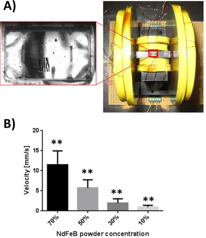
compromise between magnetic proprieties, ease of fabrication and biocompatibility. In order to properly align the magnetic powder along a specific direction of the film, thus obtaining a preferential magnetization axis, spin-coated films were put under a strong unidirectional magnetic field, before curing. The desired magnetic field was generated by means of a cylindrical permanent magnet (N35 NdFeB, diameter and height of 6 and 7 cm, respectively) placed over the film at a distance of 5.5 cm. In this way NdFeB powders, showing anisotropic properties, were properly aligned along a preferential direction, thus to maximize the superposition of magnetic effects. Once aligned the powders, the composite layer was put again under vacuum to remove all the air bubbles, and then let cure in oven (60°C for 3 h).
Finally, magnetic film samples were permanently magnetized in a nuclear magnetic resonance (NMR) machine (Bruker Advanced 3hd 400) by placing the samples with the powder alignment direction coincident with that of the machine static magnetic field (9 T) (Figure 2. 2).
Figure 2. 2 Composite film fabrication procedure.
The proposed fabrication process resulted successful for all the investigated film compositions. Membrane thickness was measured through a profilometer (Kla Tencor P10) and resulted in the range 15-35 μm depending on powder concentrations. Hirox microscope analysis (Figure 2. 3) revealed that NdFeB powders were well aligned along the selected direction, thus demonstrating the reliability of the proposed fabrication procedure.
Figure 2. 3 Hirox microscope images of a bare PDMS film and of composite samples with different NdFeB powder
concentrations.
The proposed fabrication technique allows to obtain large surface samples that can be manually shaped and used in a wide variety of applications.
In view of future microrobotics applications and with the aim to enhance fabrication precision and repeatability, a photolithography-based fabrication process was investigated. It is not straightforward to fabricate freestanding polymeric structures with traditional photolithographic and molding techniques. As a consequence, polyvinyl alcohol (PVA) sacrificial molds were exploited. An SU-8 mold was fabricated through traditional photolithography; a transfer template mold was then replicated with PVA (5% w/v) by spin coating the polymeric solution on the master mold. After curing, a replicate sacrificial PVA mold was obtained86; the PDMS-NdFeB solution (powder concentration 70%) was poured into the PVA mold and cured. Finally, film demolding was carried out by dissolving the PVA mold in water (Figure 2. 4 A). Free-standing square PDMS-NdFeB films with a side of 400 μm and a thickness of 50 μm were obtained (Figure 2. 4 B).
Figure 2. 4 (A) Composite microrobots microfabrication process. (B) Scanning Electron Microscope (SEM) image of
the microfabricated composite material-based microrobot, obtained by using a PVA sacrificial mold.
2.3 Film Magnetic characterization
A Vibrating Samples Magnetometer (VSM) (PPMS 6000, Quantum Design Ltd) was exploited to properly characterize composite films in terms of magnetic properties (Figure 2. 5 A), thus to obtain the magnetization curve of each film with a hysteresis cycle between +50 KOe and -50 KOe at 300 K (Figure 2. 5 B). The samples were aligned with their preferential magnetization axes along the magnetic field of the machine. Three independent samples were analyzed for each NdFeB powder concentration, in order to take into account the possible variability or inhomogeneity due to the fabrication process.
Typical magnetic parameters, such as saturation (Ms), remanence (Mr), susceptibility (χ) and adimensional susceptibility (χa), were extrapolated from the different curves87 and reported in Table I. In particular, considering that the typical magnetic field values used to control the film in microrobotics applications are about ±15 mT (values that are within the linear region of the curve for all samples), the susceptibility (χ) was considered constant and calculated as the first derivate of the curve in the linear region.
Results demonstrated that the composite magnetic properties strictly and linearly depend on the amount of NdFeB included. Moreover, the residual magnetization trend (Figure 2. 5 C) demonstrated the efficacy of the fabrication and magnetization procedures, thus confirming the hypothesis that the polymeric
composite films are able to act as permanent magnets with progressively stronger magnetic properties when the NdFeB powder content increases (Mr values up to 20 emu/g). Coherently, the magnetic susceptibility (Figure 2. 5 D) and the saturation magnetization (Figure 2. 5 E) linearly increase with the magnetic material concentration.
Concentrations of NdFeB powder Ms (emu/g) Mr (emu/g) χ (emu/gOe) χa
10 9.83±0.33 3.30±1.09 0.002±0.0004 0.27±0.05
30 28.16±0.92 10.46±0.32 0.0080±0.0007 0.1200±0.0100
50 35.89±4.19 14.07±2.41 0.0114±0.0018 0.1932±0.0310
70 53.25±0.18 20.41±1.06 0.0166±0.0005 0.3116±0.0088
Table I Magnetic parameters of films with different ndfeb powder concentrations
Figure 2. 5 (A) Typical magnetization curve with main parameters pointed;. (B) Magnetization curves of films
provided with different NdFeB powder concentrations. (C-E) Trends of residual magnetization Mr, magnetic susceptibility χ and saturation magnetization Ms, respectively. For each curve, both experimental points and linear
Figure 2. 6 Force diagram for a thin film-based magnetic microrobot. T, Fm, Fp, Fd, W, Tm, Fpm and TD are the
surface tension, the magnetic force, the net pressure force, the drag force, the weight force, the magnetic torque, the magnetic force generated by permanent magnets and the drag torque, respectively. The parameters ε and α are
the filling and the contact angles, respectively.
The equilibrium equation acting on the microrobot can be expressed as follows:
(2.1) 𝜌𝑉𝑝 = 𝐹𝑚+ 𝐹𝐷+ 𝑇 + 𝐹𝑝+ 𝑊
where ρ, V and p are the density, the volume and the microrobot, respectively. The magnetic force applied to the magnetic microrobot is given by:
(2.2) 𝐹𝑚= 𝑉 ∙ ∇
(
𝑀 ∙ 𝐵)
= 𝑉𝑀 ∙ ∇𝐵where V is the overall volume of the magnetic material, M is the robot magnetization and ∇B is the magnetic field gradient produced by the external source.
We assumed, in this simplified model, that the robot was a solid disk in a slow, low Reynolds number flow perpendicular to robot’s axis. Considering that, the drag force in a confined space can be expressed by88: