ICTON 2019 Fr.A1.3
978-1-7281-2779-8/19/$31.00 ©2019 IEEE 1
Distributed Coherent Radars Enabled by Fiber Networks
Paolo Ghelfi1, Leonardo Lembo1,2, Filippo Scotti1, Giovanni Serafino3, Salvatore Maresca3,and Antonella Bogoni1,3
1 PNTLab, CNIT, via Moruzzi 1, 56124 Pisa, Italy
2 CSSN Naval research Center, Italian Navy, viale Italia 72, 57126 Livorno, Italy 3 TeCIP Institute, Scuola Superiore Sant’Anna, via Moruzzi 1, 56124 Pisa, Italy
e-mail: [email protected] ABSTRACT
In the last few years, we have been proposing the use of photonics to bring new functionalities in radar systems, exploiting its precision and tunability to give radars improved performance and reconfigurability. This paper will present the most recent evolution of the original idea of photonics-based radars, which considers the exploitation of the increasingly available fiber connections to implement a network of widely distributed radars. The centralized photonic approach allows driving several separated radars simultaneously, enabling the novel class of distributed coherent radar systems. Through the implementation of specific multi-input multi-output (MIMO) processing, the photonics-enabled radar network is capable to push the radar detection resolution far beyond the limits usually set by the signal bandwidth alone.
Keywords: microwave photonics, radar network, fiber network, MIMO processing. 1. INTRODUCTION
The ever-increasing demand for high performing radars in surveillance applications pushes towards the necessity of “sensor fusion”, since standalone radars are no more sufficient to meet the operative requirements. Instead, fusing together the information from several radars allows improving the description of the observed area. However, “classical” multistatic radars employing multiple separated transmitters (TXs) and receivers (RXs) in the same area, seldom cooperate with each other. Rather, mostly due to implementation costs and sensor deployment constraints (e.g., low or no availability of high bandwidth long-range communication links between the remote nodes), they typically provide multiple uncorrelated information (e.g., target detections, trackings) to a master node for data fusion (i.e., decentralized processing). This solution simplifies the synchronization procedure and reduces the amount of data to be shared, but it also implies significant performance limitation due to the unavoidable information loss.
In such a context, centralized multiple-input multiple-output (MIMO) radars can rely on a better coordination among the network nodes [1]. Their TXs can employ different waveforms, while their RXs can process signals coming from the multiple widely distributed emitters. The increased spatial information improves the performance of target detection and localization, especially when the target exhibits a low radar cross section (RCS), or when the RCS is characterized by a high angular variability. Unfortunately, coherent MIMO radars with widely separated antennas require precise signal synchronization and reliable large-bandwidth long-range signal distribution among the network nodes. Up to now, these two issues have represented the main limitation factor to the development of such systems in real operative scenarios.
In the last two decades, microwave photonics has matured to the point of being considered an ideal candidate for the development of coherent MIMO radar networks with widely distributed antennas, as conjectured in [2]. The benefit offered by photonics is twofold: it guarantees long-time phase stability and frequency/phase coherence between the transmitted and received radio frequency (RF) signals; secondly, it allows remoting the antennas by exploiting optical fibers. In photonics-based radars, signal generation, distribution and reception leverage on the unprecedented frequency flexibility and phase noise stability guaranteed by photonics [3]. Additionally, signal distribution by means of optical fibers assures high quality and high coherence, as well as the needed large bandwidth connectivity between the radar nodes [4]. The first coherent photonics-based radar system [5] and the promising results presented in [6] pushed the scientific community to develop the first photonics-based radar network demonstrators in both laboratory [7], [8] and outdoor environments [9].
In this paper, we report on our recent investigations on fiber-based radar networks [9],[10], tested in a real outdoor scenario with multiple closely-spaced targets.
2. ARCHITECTURE OF THE PHOTONIC RADAR NETWORK
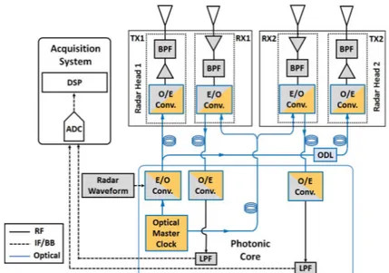
The concept of radar network developed in [9],[10] consists of a photonic core (including also the acquisition system) and several radar heads (RHs) with one TX and one RX each, that are remoted by means of optical fibers, as depicted in Fig. 1 for the case of 2 RHs.
The photonic core hosts the optical master clock, which is a solid-state mode-locked laser (MLL). In our implementations, the MLL has a pulses repetition frequency fMLL = 400 MHz that allows generating or detecting
RF carriers with extremely low phase noise (PN) upon the opto-electronic (O/E) conversion of the MLL laser in
ICTON 2019 Fr.A1.3
2 a photodiode (PD) [3], thus implementing high-quality RF up-conversion and down-conversion. Moreover, exploiting a single MLL for these operations ensures a perfect synchronization of the RHs and maintains the coherence of the signals, which is the most crucial issue in coherent MIMO radars. In the case of up-conversion, the radar signal, which is digitally generated at a low intermediate frequency (IF), is first modulated on the MLL spectrum by an electro-optic modulator, and then photodetected, generating many replicas each centered at k·fMLL± IF, with k positive integer [5], [6]. The desired RF output carrier frequency fRF can be selected by means
of a microwave filter, centered at fRF and with bandwidth larger than B, where B is the desired signal bandwidth.
In down-conversion, the RF signal is similarly modulated on the MLL, then the O/E conversion at the PD generates replicas of the RF signal down-converted at k·fMLL± IF, including the IF (for k = 0), the closest to
baseband (BB) [5]. The large MLL optical spectrum ensures high efficiency, and the wide E/O and O/E bandwidth of the available modulators and PDs allows for the flexible management of RF signals up to several tens of GHz [3].
As reported in Fig. 1, the optical master clock feeds the E/O conversion of the radar waveform in transmission as well as of the received signal. The connections between the photonic core and the TXs/RXs at the RHs are intended to exploit increasingly available deployed fiber networks. In our preliminary experiments so far, they have been realized through spans of single-mode fiber (SMF), as depicted by the coils in Fig. 1. The fiber links grant small propagation losses, absence of electromagnetic interference, and preservation of the signal coherence even with large signal bandwidth [4]. Once the E/O converted radar waveform is delivered to a TX, this operates its O/E conversion which implies the up-conversion of the IF signal to RF. In the experiments, the radar signal is generated at IF frequency fIF = 100 MHz. Thus, after proper amplification and band-pass filtering, the radar
signal is transmitted by the antenna. The employed band-pass filters (BPFs) are multi-cavity filters with -3 dB bandwidth of 100 MHz and centered at fRF = 9.7GHz. The employed antennas at the TXs are ultra-wideband
Vivaldi-shaped horn antennas with about 50° half power beam width (HPBW) aperture and 12 dBi maximum gain. The optical delay line (ODL), consisting of a 1 km-long SMF spool inserted just before the TX of RH2, implements the TDM between the two RHs. The RXs are equipped with antennas similar to those of the TXs. The detected radar echoes received by the RHs antennas are amplified, pass-band filtered and E/O converted. Then, the received signals are transmitted back to the photonic core and O/E converted. After this operation, the signals from each RX are low-pass filtered and fed into a two-channel acquisition system, where they are digitized by an analog-to-digital converter (ADC) at 400 MS/s per channel.
3. DIGITAL SIGNAL PROCESSING SCHEME
Considering the general case of a radar network with M TXs and N RXs, the photonic core shall have N ADCs digitizing the signals received by the RXs, each of these signals being the combination of the M echoes from each of the TXs, down-converted at fIF. In the following, we will indicate with the subscript k, l the generic
bistatic pair, i.e., the signal determined by the k-th TX and l-th RX, for k = 1, …, M and l = 1, …, N. First, the N digitized data streams are split into the individual bistatic channels for data processing [11]. To maximize the signal-to-noise ratio (SNR), the M×N channels are filtered at IF and then down-converted to BB. Standard radar pulse compression (i.e., matched filtering) is performed on the received pulsed signals (details of these operations can be found in [9]-[11]). The considered radar network architecture ensures excellent phase
Figure 1. Architecture of the fiber-based radar network. DSP: Digital Signal Processing; ADC: Analog-to-Digital Converter; RF: Radio Frequency; LPF: Low-Pass Filter; E/O: Electro-Optical; ODL: Optical Delay Line; O/E: Opto-Electrical; IF/BB: Intermediate Frequency/Base Band; BPF: Band-Pass Filter.
ICTON 2019 Fr.A1.3
3 coherence, because the same optical clock is used first in transmission for the up-conversion and then at the receiver for the down-conversion, for all the radar signals. Moreover, the MLL optical oscillator stands out for its low PN curve [3]. As reported in [12], if the angular jitter of the architecture is lower than 10-1 rad, the effects
on MIMO coherent detection performance are negligible. Otherwise, phase jitter could negatively affect not only target detection performance, but also increase the sidelobe level, thus introducing false alarms. The temporal jitter of the considered system architecture (i.e., the integration of the oscillator PN for offset frequencies in the interval [20 Hz, 200 MHz]) is in the order of 10-12 s, while the angular jitter is in the order of 10-2 rad, far better
than the limit identified in [12]. For this reason, coherent MIMO processing becomes possible. Under the assumption that both additive noise (AN) and PN terms are present, the signal received by the l-th RX, is [12]:
ݎ,(ݐ) = ܽ,ή ݏ ቀݐ െ ߬,(ݔ, ݕ)ቁ ݁ቂఏቀ௧ିఛೖ,(௫,௬)ቁିఏ(௧)ቃ+ ݊,(ݐ), (1)
where ݏ(ݐ) is the signal transmitted by the kth TX, ܽ, is an amplitude factor, while ߬,(ݔ, ݕ) is the time delay
proportional to the bistatic distance, which is function of the target location (ݔ, ݕ) and on the k-th TX and l-th RX positions in the Cartesian plane. The term ݊,(ݐ) represents the AN, generally modelled as an additive white
Gaussian noise (AWGN) stochastic process. The term ߠ(ݐ) takes into account the phase shift caused by the oscillator instability. If the angular jitter is below the 0.1 rad limit, the PN detrimental influence on the signal is negligible. Therefore, the following log-likelihood function suitable for a MIMO approach can be used [13]:
݈݊ൣ݂൫ݎ(ݐ)|(ݔ, ݕ)൯൧ = ܿԢ ή ቚσ σ ݁ିଶగಷఛೖ,(௫,௬) ݎ ,כ(ݐ) ή ݏ ቀݐ െ ߬,(ݔ, ݕ)ቁ ݀ݐ ே ୀଵ ெ ୀଵ ቚ + ܿᇱᇱ. (2)
According to eq. (2), for each possible target location with coordinates (ݔ, ݕ) in the Cartesian search space, the decision statistic is computed determining for all the M TXs and N RXs the correlation between the received and transmitted BB signals. Moreover, a phase term compensates the phase shift due to the time delay ߬,(ݔ, ݕ) and
to the TX-RX pair. After re-phasing each term, all the ܯ × ܰ correlation contributes are summed together coherently. For further details, see [13].
4. RECENT EXPERIMENTS AND RESULTS
In our recent experiments, the radar waveform is a linear frequency modulated pulse with 100 ns duration, pulse repetition interval (PRI) of 50 μs and B = 100 MHz centered at fRF = 9.7 GHz, with a monostatic range resolution
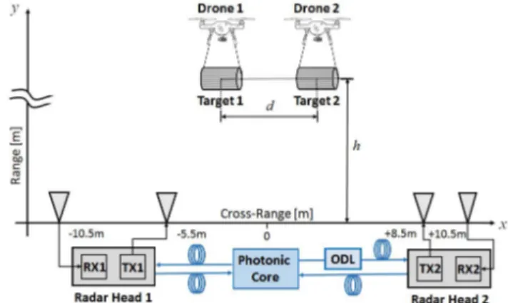
of 1.5 m. The proposed coherent radar network is tested outdoor, on the rooftop of our lab. The network is deployed, according to the scheme in Fig. 2, with the four antennas aligned over a 21 m-long baseline. These are oriented upwards, to mitigate clutter and multipath returns due to surrounding structures, buildings and vegetation, and to ensure the simultaneous illumination of both targets. The output power from each TX antenna is 100 mW. The targets consist of two cylinders, with 17 cm radius and 50 cm height, made of a tight-mesh metal net and hanging from two mini-drones. The height of the two targets was controlled and kept always between 15 and 20 m, while the two drones were hovering at the same height h = 18 m at about a distance d = 3 m.
Figure 2. Geometry of the coherent photonics-based MIMO radar network and in-field experimental setup. The experiment is realized with a scaled-down geometry. However, the presence of a long spool of fiber (the ODL in Fig. 1) simulates a distance of about 1 km between the two RHs. In the following, the results will demonstrate the low attenuation and negligible phase distortion introduced by the fiber. Moreover, we can consider the network being characterized by widely distributed antennas, since the four channels are spatially decorrelated, [1]. Before evaluating the decision statistics (i.e. the normalized cross ambiguity functions), the stream acquired by the ADC is digitally filtered with an ideal BPF with 100 MHz bandwidth centered at fIF.
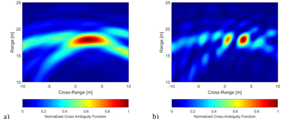
Then, the signal is down-converted to BB and the four channels are extracted. The fused signal output is evaluated over a 25 ms integration time (i.e., 500 PRIs). Then, both the non-coherent and coherent MIMO processing outputs are evaluated in a search space in the interval [10, 25] m and [-10, 10] m (with 10 cm
ICTON 2019 Fr.A1.3
4 spacing), along range and cross-range, respectively. Results are depicted in Fig. 3(a) and 3(b), respectively. As can be observed in Fig. 3(a), the two targets are too close to be correctly separated in the cross-range with a standard non-coherent processing. Fig. 3 (b) depicts instead the output of the coherent MIMO processing case. Here, the two targets are correctly separated in range, around 3 m apart from each other. Thus, the cross-range resolution has been improved by a factor of 5.
a) b)
Figure 3. Non-coherent (a) versus coherent MIMO processing output in the reported multi-target scenario. 5. CONCLUSIONS AND PERSPECTIVES
In this paper, our recent results on coherent MIMO radar networks based on photonic technology have been reported. The results obtained during the preliminary tests confirm that photonics is an enabling technology for coherent MIMO radars with widely distributed antennas, thanks not only to its capability to preserve signal coherence among the TX and RX elements, but also to its granted large-bandwidth long-range undistorted signal distribution over fiber. Given the reduced MIMO configuration and the non-idealities introduced by the environment and target RCS fluctuations, the results obtained in terms of cross-range resolution are truly remarkable. Despite the very preliminary setup, such results demonstrate the decisive impact of photonics in the design and development of coherent MIMO radars with widely separated antennas.
ACKNOWLEDGEMENTS
This work has been partially supported by the NATO SPS project “SOLE”, and by the Italian project PREVENTION with the contribution of the Ministry of Foreign Affairs, Directorate General for the Country Promotion.
REFERENCES
[1] A. M. Haimovich et al., “MIMO radar with widely separated antennas,” IEEE Signal Processing Magazine, vol. 25, no. 1, pp. 116-129, Jan. 2008.
[2] L. Lembo et al., “Analysis of a coherent distributed MIMO photonics-based radar network,” in Proc. 15th European Radar Conference (EuRAD), Madrid, Spain, Sept. 2018.
[3] G. Serafino et al., “Phase and amplitude stability of EHF-band radar carriers generated from an active mode-locked laser,” Journal of Lightwave Technology, vol. 29, no. 23, Dec. 2011.
[4] P. A. Williams et al., “High-stability transfer of an optical frequency over long fiber-optic links,” Journal of Optical Society of America B, vol. 25, pp. 1284-1293, 2008.
[5] P. Ghelfi et al., “A fully photonics-based coherent radar system,” Nature, vol. 507, Mar. 2014.
[6] F. Laghezza et al., “Field evaluation of a photonics-based radar system in a maritime environment compared to a reference commercial sensor,” IET Radar, Sonar and Navigation, vol. 9, no. 8, pp. 1040-1046, Oct. 2015.
[7] J. Fu et al., “A fiber-distributed bistatic ultra-wideband radar based on optical time division multiplexing,” in Proc. 2015 Int. Topic. Meet. on Microwave Photonics (MWP), Paphos, Cyprus, 2015.
[8] F. Zhang et al., “Photonics-based MIMO radar with high-resolution and fast detection capability,” Optics Express, vol. 26, no. 13, pp. 17529-17540, 2018.
[9] L. Lembo et al., “In-field demonstration of a photonic coherent MIMO distributed radar network,” in Proc. IEEE Radar Conference 2019, Boston (MA), USA (accepted).
[10] S. Maresca, G. Serafino, F. Scotti, F. Amato, L. Lembo, A. Bogoni, and P. Ghelfi, “Photonics for coherent MIMO radar: An experimental multi-target surveillance scenario, ” in Proc. Int. Radar Symp., Ulm, Germany, 2019 (accepted). [11] G. A. Richards, “Fundamentals of Radar Signal Processing,” 2nd Ed., McGraw-Hill, 2014.
[12] I. Pasya et al., “Detection performance of M-sequence-based MIMO radar systems considering phase jitter effects,” IEEE Phased Array Systems and Technology Symp., Oct. 2013.
[13] N. H. Lehmann et al., “High resolution capabilities of MIMO radar,” in Proc. 40th IEEE Asilomar Conf. on Signals System and Computers, Pacific Groove, CA, USA, Oct.-Nov. 2006.