Active fibre-reinforced composites
with embedded shape memory alloys
by
Federica Daghia
Relatore: Prof. Ing. Erasmo Viola
Correlatore: Prof. Ing. Francesco Ubertini
Dottorato di ricerca in Meccanica delle Strutture – XX ciclo
Coordinatore: Prof. Ing. Erasmo Viola
Keywords:
adaptive structures, fibre-reinforced composites, shape memory alloys
Settore scientifico disciplinare:
Area 08 – Ingegneria Civile e Architettura
ICAR/08 – Scienza delle Costruzioni
ALMA MATER STUDIORUM • Universit`a di Bologna
Bologna, 23 marzo 2008
between theory and practice.
But, in practice, there is.
Contents
List of Figures v List of Tables ix Sommario 1 Introduction 3 Capitolo 1 – Sommario 71 Active fibre-reinforced composites 9
1.1 Reinforcement . . . 11 1.2 Matrix . . . 15 1.3 Manufacturing process . . . 16 1.3.1 Hand lay-up . . . 17 1.3.2 Spray-up . . . 18 1.3.3 Moulding . . . 18 1.3.4 Pultrusion . . . 20 1.3.5 Filament winding . . . 20 1.4 Active materials . . . 20 1.4.1 Electrical coupling . . . 21 1.4.2 Thermal coupling . . . 22 1.4.3 Magnetic coupling . . . 22 1.4.4 Chemical coupling . . . 23 Capitolo 2 – Sommario 25
2 Modelling of fibre-reinforced composites 27
2.1 Analytical modelling of laminated plates . . . 28
2.1.1 Equivalent Single Layer theories . . . 30
2.2 A hybrid-stress finite element for laminated plates . . . 52
2.2.1 Hybrid stress formulation . . . 53
2.2.2 Finite element assumptions . . . 54
2.2.3 Finite element equations . . . 57
2.2.4 Numerical testing of the finite element performance . . . 59
2.3 Reconstruction of the transverse stresses . . . 66
2.3.1 Recovery by Compatibility in Patches . . . 68
2.3.2 Reconstruction of the transverse shear stresses . . . 71
2.3.3 Reconstruction of the transverse normal stress . . . 71
2.3.4 Numerical testing of the reconstruction procedure . . . . 72
2.4 Bayesian estimation of laminates’ elastic constants . . . 78
2.4.1 Bayesian estimators comparison . . . 80
2.4.2 A modified procedure . . . 92
2.4.3 Testing of the estimator procedures . . . 95
Capitolo 3 – Sommario 103 3 Shape memory alloys 105 3.1 Shape memory alloy properties . . . 106
3.1.1 Martensitic phase transitions . . . 110
3.1.2 Micromechanical interpretation of shape memory alloy properties . . . 113
3.2 Shape memory alloy applications . . . 115
3.2.1 Couplings and fasteners . . . 116
3.2.2 Actuators . . . 116
3.2.3 Biomedical devices . . . 117
3.2.4 Civil engineering applications . . . 118
3.3 Modelling of shape memory alloys . . . 120
3.3.1 Outline of phenomenological thermodynamics . . . 121
3.3.2 Outline of plasticity theories . . . 124
3.3.3 One-dimensional models . . . 125
3.3.4 Three-dimensional models . . . 141
3.4 Experimental characterisation and modified phase diagram . . . 158
3.4.1 Detwinned martensite formation at low stress levels . . . 159
3.4.2 Influence of the loading path on the reverse phase transi-tion temperatures . . . 165
Capitolo 4 – Sommario 179 4 Active composites with shape memory alloy wires 181
4.1 Modelling SMAHC . . . 184
4.1.1 Finite element formulation . . . 187
4.1.2 Host structure plate element . . . 188
4.1.3 Shape memory alloy wire element . . . 190
4.1.4 Numerical validation . . . 192
4.2 Building and testing shape control SMAHC . . . 193
4.2.1 SMAHC beam . . . 194
4.2.2 SMAHC plate . . . 205
Conclusions and perspectives 219
List of Figures
1.1 Typical stress-strain curves for various fibres . . . 12
1.2 Specific properties of fibres and bulk materials . . . 12
1.3 Types of reinforcement . . . 14
1.4 Production rate versus quality of the composite for some manu-facturing processes . . . 16
1.5 Laminae fibre orientation . . . 18
1.6 Classification of some active materials according to the stress-strain response . . . 21
2.1 Plate-like body . . . 31
2.2 Material and problem coordinate systems . . . 32
2.3 Generalised strains for the CLPT . . . 34
2.4 Generalised strains for the FSDT . . . 39
2.5 Generalised strains for the HSDT . . . 44
2.6 Coordinate systems for the plate element . . . 54
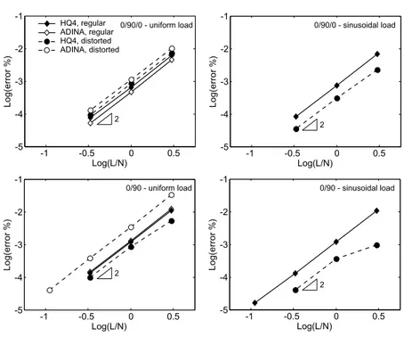
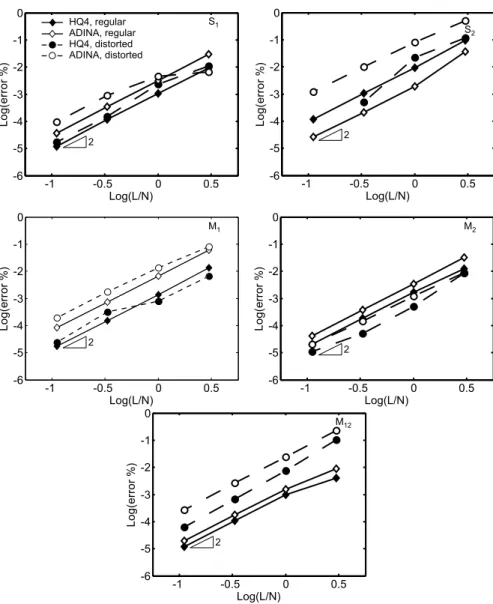
2.7 Simply supported square plate, regular and distorted mesh patterns 59 2.8 Convergence in energy norm for sinusoidal load and both the stacking sequences . . . 60
2.9 Convergence of the transverse displacement at point A for differ-ent loads and stacking sequences . . . 61
2.10 Convergence of the in-plane displacement at point B for the (0/90) stacking sequence and both uniform and sinusoidal load . 61 2.11 Convergence of the stress resultants at point C for the (0/90/0) stacking sequence and uniform load . . . 62
2.12 Convergence of the stress resultants at point C for the (0/90) stacking sequence and uniform load . . . 63
2.14 Convergence in energy norm of the shear stress profiles for sinu-soidal load and both the stacking sequences, using HQ4 with or
without RCP recovery . . . 73
2.15 Convergence of the moments at point D by HQ4 with or without RCP recovery, for the (0/90/0) stacking sequence and sinusoidal load . . . 74
2.16 Convergence of the moments at point D by HQ4 with or without RCP recovery, for the (0/90) stacking sequence and sinusoidal load 74 2.17 Shear stress profiles at point C using RCP recovery on various regular meshes, for the stacking sequence (0/90/0) and sinusoidal load . . . 76
2.18 Shear stress profiles at point C using RCP recovery on various regular meshes, for the stacking sequence (0/90) and sinusoidal load . . . 76
2.19 Shear stress profiles at point C with and without RCP recovery on 9×9 meshes for the stacking sequence (0/90/0) and sinusoidal load . . . 77
2.20 Shear stress profiles at point C with and without RCP recovery on 9 × 9 meshes for the stacking sequence (0/90) and sinusoidal load . . . 77
2.21 Forward sensitivity analysis for Plate 1 . . . 90
2.22 Forward sensitivity analysis for Plate 2 . . . 91
2.23 Natural modes corresponding to the frequencies considered in the analysis (Plate 2c) . . . 96
3.1 Shape memory effect . . . 107
3.2 Superelasticity . . . 107
3.3 Shape memory effect and superelasticity . . . 108
3.4 Shape recovery under applied load . . . 109
3.5 One-way and two-way shape memory effect . . . 110
3.6 Formation of different martensitic variants in a single grain of polycrystalline CuZnAl alloy during uniaxial tensile loading (Pa-toor et al., 2006) . . . 111
3.7 Crystal structures and arrangements in the stress-temperature plane . . . 111
3.8 Free energy of austenite and martensite as a function of temperature112 3.9 Loading path and phase transitions for the shape memory effect 114 3.10 Loading path and phase transitions for superelasticity . . . 114
3.11 Phase diagrams for Tanaka (1986), Liang and Rogers (1990) and
Brinson (1993) models . . . 128
3.12 Phase diagrams for Auricchio and Sacco’s models . . . 132
3.13 Internal variables for Popov and Lagoudas (2007) model . . . 144
3.14 Phase diagram for Popov and Lagoudas (2007) model . . . 149
3.15 Schematic representation of a DSC measurement for shape mem-ory alloys . . . 151
3.16 Uniaxial phase diagrams . . . 158
3.17 Constrained recovery sketch in Brinson’s phase diagram . . . 160
3.18 Nitinol wires in constrained recovery . . . 161
3.19 Comparison between original and modified Brinson’s models . . . 164
3.20 DSC for shape memory alloy wire with 4% elongation . . . 166
3.21 DSC test for the virgin specimen . . . 167
3.22 First heating curve for specimens strained at room temperature . 170 3.23 Strain versus peak temperature values for test 1 . . . 171
3.24 First heating curve for specimens strained at room temperature - detail of 2% strain . . . 171
3.25 First heating curve for specimens thermally cycled under 200 MPa constant stress . . . 172
3.26 Applied stress versus peak temperature values for test 2 . . . 173
3.27 First heating curve for specimens thermally cycled at 4% constant strain . . . 175
4.1 SMAHC plate and reference systems . . . 189
4.2 Rigid body connections . . . 191
4.3 Numerical validation: stiffness and shape control . . . 192
4.4 SMAHC specimen . . . 197
4.5 Experimental setup for the SMAHC beam . . . 198
4.6 SMAHC beam response - cycle 1 . . . 200
4.7 SMAHC beam response - cycles 1, 3 and 5 . . . 200
4.8 SMAHC beam response - cycles 1, 3, 5 and 10 . . . 201
4.9 Simulation of SMAHC beam response - cycle 1 . . . 203
4.10 Simulation of SMAHC beam response - cycles 1, 3 and 5 . . . 203
4.11 Simulation of SMAHC beam response - cycles 1, 3, 5 and 10 . . . 204
4.12 VARTM lay-up . . . 206
4.13 VARTM composite making . . . 206
4.14 VARTM plate actuation . . . 207
4.15 DSC measurement on trained wires . . . 209
4.17 Pre-preg SMAHC plate . . . 212
4.18 Experimental setup for the pre-preg SMAHC plate . . . 213
4.19 Pre-preg SMAHC plate actuation . . . 214
4.20 Pre-preg SMAHC plate response for different cycles . . . 215
List of Tables
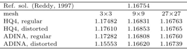
2.1 Transverse displacement ¯w at point A for simply supported (0/90/0)
laminate subjected to uniform load . . . 63
2.2 Transverse displacement ¯w at point A and in-plane displacement ¯ u1 at point B for simply supported (0/90) laminate subjected to uniform load . . . 64
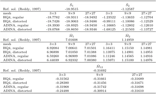
2.3 Stress resultants at point C for simply supported (0/90/0) lami-nate subjected to uniform load . . . 64
2.4 Stress resultants at point C for simply supported (0/90) laminate subjected to uniform load . . . 65
2.5 Characteristics of Plate 1 and Plate 2 . . . 87
2.6 Input frequencies of Plate 1 and Plate 2 . . . 87
2.7 Test 1 on Plate 1: final estimates and iterations . . . 88
2.8 Test 2 on Plate 1: final estimates and iterations . . . 88
2.9 Test 3 on Plate 1: final estimates and iterations . . . 88
2.10 Test 1 on Plate 2: final estimates and iterations . . . 89
2.11 Test 2 on Plate 2: final estimates and iterations . . . 89
2.12 Test 3 on Plate 2: final estimates and iterations . . . 89
2.13 Test 1 on Plate 1: MVE-mod final estimates and iterations . . . 93
2.14 Test 2 on Plate 1: MVE-mod final estimates and iterations . . . 93
2.15 Test 3 on Plate 1: MVE-mod final estimates and iterations . . . 94
2.16 Test 1 on Plate 2: MVE-mod final estimates and iterations . . . 94
2.17 Test 2 on Plate 2: MVE-mod final estimates and iterations . . . 94
2.18 Test 3 on Plate 2: MVE-mod final estimates and iterations . . . 95
2.19 Characteristics of Plate 1c and Plate 2c . . . 97
2.20 Input frequencies of Plates 1c and 2c . . . 97
2.22 Final estimates and iterations for Plate 2c - pseudoexperimental frequencies . . . 98 2.23 Characteristics of cross-ply and angle-ply plates . . . 99 2.24 Input frequencies for cross-ply and angle-ply plates . . . 99 2.25 Final estimates and iterations for cross-ply and angle-ply plates . 99 2.26 Characteristics of carbon-epoxy plate . . . 101 2.27 Measured frequencies for carbon-epoxy plate . . . 101 2.28 Estimates for carbon-epoxy plate . . . 101 3.1 Comparison between the different models proposed by Auricchio
and Sacco . . . 131 3.2 Nitinol material properties . . . 163 4.1 Axial and flexural rigidities of laminate strips . . . 195 4.2 Constitutive matrices for the finite element model, units N and
mm . . . 196
4.3 Nitinol wires: material properties . . . 196 4.4 Pre-preg glass fibres composite lamina: material properties . . . 209 4.5 Trained Nitinol wires: material properties . . . 209
Compositi fibro-rinforzati attivi
con leghe a memoria di forma
La tesi riguarda i compositi fibro-rinforzati contenenti fili a memoria di forma. L’applicazione strutturale dei materiali attivi permette lo sviluppo di struttu-re adattive, in grado di rispondestruttu-re attivamente a cambiamenti dell’ambiente circostante. In particolare, attuatori a memoria di forma inseriti in un com-posito ne controllano la forma o la rigidezza, influenzando le propriet`a statiche e dinamiche del composito stesso. Le applicazioni possibili sono molteplici ed includono la prevenzione dell’instabilit`a termica di pannelli esterni di aeromo-bili, il controllo della forma per il miglioramento aerodinamico e l’apertura e il posizionamento di strutture spaziali espandibili.
Lo studio dei compositi attivi `e un argomento complesso e multidisciplinare, che richiede una profonda comprensione del comportamento accoppiato tipico dei materiali attivi, oltre che dell’interazione tra i diversi costituenti del compo-sito. Sia i compositi fibro-rinforzati che le leghe a memoria di forma sono argo-menti di ricerca molto attivi, che presentano una serie di problemi aperti di tipo sia sperimentale che di modellazione. Per questo, nonostante la tesi si concentri sui compositi attivi, alcuni risultati qui presentati possono essere utilizzati nel contesto dei compositi fibro-rinforzati tradizionali o di altre applicazioni delle leghe a memoria di forma.
Il corpo della tesi `e suddiviso in quattro capitoli.
Nel primo capitolo sono introdotti i compositi attivi fibro-rinforzati, pre-sentando una breve panoramica sulle principali tipologie di rinforzo, matrice e processo produttivo per i materiali compositi, insieme ad una introduzione e classificazione di alcuni materiali attivi.
Nel secondo capitolo sono esaminate alcune problematiche relative ai compo-siti fibro-rinforzati tradizionali. I principali modelli bidimensionali per piastre composite vengono derivati a partire da un solido tridimensionale soggetto a vincoli cinematici. Nel contesto della teoria al primo ordine, viene formulato un nuovo elemento finito semplice, accurato e computazionalmente efficiente, a partire da un approccio ibrido agli sforzi. La soluzione del problema bidi-mensionale `e utilizzata per la ricostruzione delle tensioni lungo lo spessore del laminato e si sviluppa una procedura in due fasi che utilizza il Recovery by Compatibility in Patches, formulato recentemente e qui esteso al caso di
pia-stre laminate, per migliorare l’accuratezza della soluzione bidimensionale. La modellazione di elementi compositi anisotropi richiede di determinare un signifi-cativo numero di parametri elastici, che possono essere stimati tramite tecniche numerico-sperimentali. In questo contesto, vengono analizzati due diversi esti-matori bayesiani, evidenziando analogie e differenze tra i due. Inoltre, viene proposta una procedura alternativa per migliorare la velocit`a di convergenza.
Nel terzo capitolo sono introdotte le leghe a memoria di forma, descrivendone propriet`a e principali applicazioni. Diversi modelli costitutivi mono e triassiali di letteratura, basati su analogie con la plasticit`a, sono messi a confronto in maniera critica, evidenziandone potenzialit`a e limiti, legati principalmente alla definizione del diagramma di fase e alla scelta delle variabili interne. Successiva-mente, sono riportati alcuni risultati sperimentali sulla caratterizzazione di fili a memoria di forma. Tali risultati evidenziano fenomeni non rappresentati dalla corrente modellazione costitutiva; si propongono alcune idee per lo sviluppo di un modello alternativo.
Il quarto capitolo riguarda le piastre composite attive con fili a memoria di forma. Gli approcci di modellazione che possono essere impiegati per descrivere il comportamento di tali strutture sono numerosi e presentano differenti van-taggi e svanvan-taggi, sia dal punto di vista della complessit`a che della versatilit`a. Un modello semplice, utile per descrivere le configurazioni di controllo della forma e della rigidezza in un contesto comune, `e proposto e implementato. Suc-cessivamente, il modello `e validato sperimentalmente, facendo riferimento alla configurazione di controllo della forma, la quale risulta essere la pi`u sensibile alla scelta dei parametri del modello. Il lavoro sperimentale `e suddiviso in due parti. Nella prima parte, un elemento composito attivo `e realizzato incollando alcuni fili a memoria di forma predeformati su una striscia di laminato in fibra di carbonio. Si tratta di una struttura relativamente semplice da realizzare, ma utile a dimostrare sperimentalmente il concetto illustrato nella prima parte del capitolo. Nella seconda parte, si affrontano le problematiche relative alla rea-lizzazione di un vero e proprio composito fibro-rinforzato con fili a memoria di forma integrati, considerando diverse scelte in termini di materiali e tecnologie impiegate. Anche se rimangono da affrontare diversi aspetti tecnologici, i risul-tati ottenuti dalla sperimentazione permettono di dimostrare il meccanismo di funzionamento dei compositi con fili a memoria di forma, risultando inoltre in ottimo accordo con le previsioni del modello proposto.
Introduction
This dissertation concerns active fibre-reinforced composites with embedded shape memory alloy wires. The structural application of active materials al-lows to develop adaptive structures which actively respond to changes in the environment, such as morphing structures, self-healing structures and power harvesting devices. In particular, shape memory alloy actuators integrated within a composite actively control the structural shape or stiffness, thus in-fluencing the composite static and dynamic properties. Envisaged applications include, among others, the prevention of thermal buckling of the outer skin of air vehicles, shape changes in panels for improved aerodynamic characteristics and the deployment of large space structures.
The study and design of active composites is a complex and multidisciplinary topic, requiring in-depth understanding of both the coupled behaviour of ac-tive materials and the interaction between the different composite constituents. Both fibre-reinforced composites and shape memory alloys are extremely ac-tive research topics, whose modelling and experimental characterisation still present a number of open problems. Thus, while this dissertation focuses on active composites, some of the research results presented here can be usefully applied to traditional fibre-reinforced composites or other shape memory alloy applications.
The dissertation is composed of four chapters.
In the first chapter, active fibre-reinforced composites are introduced by giv-ing an overview of the most common choices available for the reinforcement, matrix and production process, together with a brief introduction and classifi-cation of active materials.
the modelling of fibre-reinforced composites. Different two-dimensional lami-nate theories are derived from a parent three-dimensional theory, introducing a procedure for the a posteriori reconstruction of transverse stresses along the laminate thickness. Accurate through the thickness stresses are crucial for the composite modelling as they are responsible for some common failure mecha-nisms. A new finite element based on the First-order Shear Deformation Theory and a hybrid stress approach is proposed for the numerical solution of the two-dimensional laminate problem. The element is simple and computationally effi-cient. The transverse stresses through the laminate thickness are reconstructed starting from a general finite element solution. A two stages procedure is de-vised, based on Recovery by Compatibility in Patches and three-dimensional equilibrium. Finally, the determination of the elastic parameters of laminated structures via numerical-experimental Bayesian techniques is investigated. Two different estimators are analysed and compared, leading to the definition of an alternative procedure to improve convergence of the estimation process.
The third chapter focuses on shape memory alloys, describing their proper-ties and applications. A number of constitutive models proposed in the litera-ture, both one-dimensional and three-dimensional, are critically discussed and compared, underlining their potential and limitations, which are mainly related to the definition of the phase diagram and the choice of internal variables. Some new experimental results on shape memory alloy material characterisation are also presented. These experimental observations display some features of the shape memory alloy behaviour which are generally not included in the current models, thus some ideas are proposed for the development of a new constitutive model.
The fourth chapter, finally, focuses on active composite plates with embed-ded shape memory alloy wires. A number of different approaches can be used to predict the behaviour of such structures, each model presenting different ad-vantages and drawbacks related to complexity and versatility. A simple model able to describe both shape and stiffness control configurations within the same context is proposed and implemented. The model is then validated considering the shape control configuration, which is the most sensitive to model parame-ters. The experimental work is divided in two parts. In the first part, an active composite is built by gluing prestrained shape memory alloy wires on a carbon fibre laminate strip. This structure is relatively simple to build, however it
is useful in order to experimentally demonstrate the feasibility of the concept proposed in the first part of the chapter. In the second part, the making of a fibre-reinforced composite with embedded shape memory alloy wires is inves-tigated, considering different possible choices of materials and manufacturing processes. Although a number of technological issues still need to be faced, the experimental results allow to demonstrate the mechanism of shape control via embedded shape memory alloy wires, while showing a good agreement with the proposed model predictions.
Compositi fibro-rinforzati attivi
I materiali compositi sono formati da due o pi`u costituenti diversi, ciascuno dei quali contribuisce a determinarne il comportamento complessivo. Pi`u comune-mente, il termine compositi si riferisce a materiali costituiti da una matrice la cui funzione `e di unire e proteggere le fibre, che costituiscono il principale elemento resistente del composito. Anche limitandosi ai soli compositi fibro-rinforzati si riscontra un’enorme variet`a di materiali diversi.
Tra i primi ad interessarsi di compositi fu negli anni ’60 l’industria aerospa-ziale, in cerca di soluzioni per la realizzazione di componenti dal peso ridotto. Negli ultimi decenni, i compositi hanno cominciato ad essere utilizzati in altri settori, quali l’industria automobilistica, sportiva e delle costruzioni.
Il principale vantaggio nell’utilizzo dei materiali compositi `e l’ottimo rap-porto peso/resistenza, oltre alla possibilit`a di progettare il materiale a seconda delle necessit`a strutturali. Definendo la posizione delle fibre e il numero di strati `e possibile progettare le propriet`a del materiale in funzione della direzione di caricamento e dei requisiti locali di resistenza e rigidezza. Questa flessibilit`a implica per`o una notevole complessit`a associata alla progettazione di strutture composite rispetto alle strutture tradizionali, dato che il materiale e il processo di produzione devono essere definiti insieme alla struttura stessa.
Questi problemi, in aggiunta al costo ancora elevato dei materiali composi-ti, hanno finora ritardato l’utilizzo di tali materiali in applicazioni strutturali. Recentemente la tendenza si sta invertendo e cominciano a nascere nuove idee sulle possibili combinazioni di materiali diversi per ottenere un’infinita variet`a di propriet`a strutturali. Lo sviluppo di materiali attivi, quali i materiali pie-zoelettrici e le leghe a memoria di forma, ha aperto la strada alla realizzazione di compositi attivi. I materiali attivi mostrano un accoppiamento tra il campo meccanico e altri campi della fisica (termico, elettrico, magnetico, ecc.), che pu`o essere sfruttato per realizzare sensori o attuatori. Inserendo un materiale attivo in un composito, questo svilupper`a caratteristiche attive. La principale applica-zione dei compositi attivi consiste nel controllo delle propriet`a strutturali, che possono adattarsi a cambiamenti delle condizioni esterne.
Lo sviluppo dei compositi attivi presenta ulteriori difficolt`a rispetto ai com-positi fibro-rinforzati tradizionali. La modellazione di comcom-positi attivi richiede la descrizione del campo meccanico e di quello accoppiato, coinvolgendo
mecca-nismi di accoppiamento che in alcuni casi non sono ancora pienamente compresi. Per materiali attivi di recente concezione, inoltre, non sono ancora disponibili informazioni sul comportamento a lungo termine. Tutte queste difficolt`a ren-dono i compositi attivi un tema di ricerca molto complesso e promettente, che coinvolge numerose discipline (chimica, scienza dei materiali, ingegneria strut-turale, etc.) per ottenere comportamenti strutturali che sarebbero impensabili con materiali tradizionali.
In questo capitolo, una breve descrizione di alcune tra le pi`u comuni possi-bilit`a a disposizione per la definizione del rinforzo, della matrice e del processo produttivo per i compositi fibro-rinforzati tradizionali, insieme ad una panora-mica su alcuni materiali attivi, permette di illustrare le enormi potenzialit`a dei compositi attivi.
Chapter 1
Active fibre-reinforced
composites
Composites are materials made up of two or more constituents, each bestowing different characteristics on the overall material behaviour. A number of very different materials belong to this broad category, from traditional structural materials such as concrete and masonry all the way to newly devised polymers with embedded nanoparticles such as carbon nanotubes.
More commonly, the term composite refers to materials constituted by a ma-trix, whose function is to bind together and protect the fibres, which constitute the main load-bearing elements of the composite. Even within the narrower definition of fibre-reinforced composites, the variety of available materials is enormous. In particular, composites can be classified according to the type of matrix, reinforcement and technological process (Edwards, 1998).
Fibre-reinforced composites are becoming increasingly popular in a wide range of applications. Historically, among the first to take an interest in com-posites was the aerospace industry in the 1960s (Soutis, 2005). The main reason was the significant decrease in weight of composites as compared to traditional materials. In the last decades, however, composites have started to penetrate other industries, such as automotive, sporting goods and construction, where they are mainly used as reinforcement to repair and enhance the performance of existing structures (Bastianini et al., 2005; Stratford et al., 2004).
Among the advantages of composite materials are the high strength to weight ratio and the possibility to tailor the material to the structural needs. Indeed, by selecting the fibre placement and number of layers it is possible to design the material properties according to the direction of loading and the locally required strength and stiffness properties. This, however, implies a significant complexity in the design of composite structures as compared to traditional ones, since the material and the production process need to be designed together with the structure itself. Moreover, the material behaviour of composites in both elastic and inelastic range is rather complex to predict, as it involves mesoscale interaction of the different constituents.
The mentioned issues, together with the still high cost of composite materials as compared to traditional solutions, have delayed the massive use of composites in structural applications. In recent years, however, the interest in these kinds of materials has been ever increasing. A significant example of the advances in composite use is the new aircraft Boeing 787 Dreamliner, scheduled to enter into service in 2008: it is the first aircraft whose primary structure is made for as much as 50% of composites — including the fuselage and the wing. In this case, the use of composites greatly simplifies the structural elements: by manufacturing a one-piece fuselage section, the designers were able to eliminate 1,500 aluminium sheets and 40,000 - 50,000 fasteners (source: Boeing website1).
As fibre-reinforced composites become established, more ideas arise on how best to combine different materials to achieve a virtually infinite variety of structural properties. The development of active materials, such as piezoelectric materials and shape memory alloys, has paved the way to the creation of active composites. Active materials (also referred to as smart or intelligent materials) exhibit coupling between the mechanical field and some other physical field (thermal, electric, magnetic etc.), thus a stimulus in one of the fields provokes a response in the coupled field. This coupling can be exploited for sensing and/or actuation. In sensing, a stimulus in the mechanical field provokes a response in the coupled field which can be measured, while in actuation the coupled field is used to provoke a mechanical response. By embedding an active material in a composite, the composite itself can exhibit active properties.
Active composites can be used for many purposes, the main idea being to control and adapt the structural properties according to a change in external
conditions (adaptive composites). Embedded sensing allows to monitor the structural conditions, while actuators can change the dynamic properties, stiff-ness or shape according to need. Even more, embedded systems can be designed with self-diagnosis and self-healing features.
The development of active composites poses even more challenges than tra-ditional fibre-reinforced composites. Modelling active materials requires to take into account both the mechanical and the coupled field, thus increasing the size and complexity of the problem and, in many cases, introducing sources of non linearity. Moreover, in some cases the mechanisms underlying the coupled be-haviour are still not fully understood, thus further investigation on the active material itself is required prior to considering the composite. Finally, for many active materials of recent conception not much information is available regard-ing the long term behaviour, such as fatigue life and stability of the response with increasing numbers of cycles. All the stated difficulties make active com-posites a very challenging yet promising topic for researchers, which involves many different disciplines (chemistry, material science, structural engineering etc.) working together to achieve structural performances which would have been unthinkable with traditional materials.
An overview of the most common choices available for the reinforcement, ma-trix and production process for traditional fibre-reinforced composites (Mazum-dar, 2002), together with a brief introduction and classification of active mate-rials, allow to get a glimpse of the enormous potential of active fibre-reinforced composites.
1.1
Reinforcement
Fibres are the main load-bearing element of the composite, thus it is mostly on the choice of the reinforcement that the composite mechanical properties depend. Choosing a reinforcement requires to define the type of fibres, their size and arrangement.
Fibres can be made of a wide variety of materials, both inorganic (e.g. metal, glass, carbon fibres) and organic (e.g. aramidic, natural fibres). Because of the small size of the cross-section (5 to 25 µm for the most common fibres) and the reduced amount of defects, fibres are generally stiffer and stronger than material in bulk form and tend to break in a fragile manner. In Figure 1.1, typical stress
0 0.005 0.01 0.015 0.02 0.025 0.03 0 0.5 1 1.5 2 2.5 strain stress(GPa) E - glass S - glass
Carbon HM Carbon HS Kevlar 49 Kevlar 29
Figure 1.1: Typical stress-strain curves for various fibres
0 50 100 150 200 0 0.5 1 1.5 2 2.5
Specific modulus (GPa cm /g)3
S pecificstrength(GPacm /g) 3 Carbon HS Carbon HM Kevlar 49 Kevlar 29 S - glass E - glass Steel Aluminum
strain curves in uniaxial tension are shown for various types of fibres, whereas in Figure 1.2 the specific properties of various fibres are compared with those of bulk steel and aluminium.
Glass fibres are the cheapest among the reinforcements, thus they are the most common in applications. Their elastic modulus is comparatively low (slightly better for the S-glass type than the E-glass), thus they are used for both structural and non structural applications. Carbon fibres come in differ-ent varieties, classified as high strength and high modulus fibres. Their elas-tic modulus and specific elaselas-tic modulus are the highest, thus they are often favoured in low-weight structural applications. However, their cost is signifi-cantly higher than that of glass fibres. Aramidic fibres are synthetic organic fibres, also known with the commercial name of Kevlar. When drawn, aramidic fibres acquire anisotropic properties, thus their behaviour in compression is sig-nificantly worse than in tension. Because of their microstructure, aramidic fibres break in a more ductile way as compared to glass or carbon fibres; for this rea-son they are used in applications where energy dissipation is required, such as motorcycle helmets and bulletproof vests.
A variety of different reinforcements can be obtained from the same type of fibres, from thin two dimensional mats or fabrics to complex-shaped three-dimensional preforms. The properties of the resulting composite depend mainly on the fibre length (long versus short fibres) and orientation (random versus oriented). In general, the best material properties are obtained with long con-tinuous fibres which are oriented in the loading direction. This situation allows to maximise the use of the material, but yields extremely anisotropic compos-ites and may not be the best configuration, depending upon the application and manufacturing process. Nearly isotropic properties can be obtained with randomly oriented fibres, which can be held together with a resinous binder to form a mat. Depending upon the length of the fibres, this is called chopped fibres mat (short fibres, Figure 1.3(a)) or continuous mat (long fibres, Figure 1.3(b)).
Long continuous oriented fibres are arranged in bundles called rovings, which can be used to make woven or non woven fabric. Woven fabric is made of fibres woven together to form a single layer and it is classified according to the weave style. Some common weave styles are shown in Figure 1.3(d). The weave style defines the amount of fibres in each direction, thus it influences the degree of
(a) Chopped fibres mat (b) Continuous mat (c) Non crimp fabric plain weave satin weave twill weave
(d) Some weave styles for woven fabric
Figure 1.3: Types of reinforcement
in-plane anisotropy of the composite. In plain weave, for example, the same amount of fibres are laid along two orthogonal directions, thus the composite properties along these two directions are the same. Non woven fabric, also called non crimp fabric, is made of fibres aligned parallel to each other and stitched together with polyester thread (Figure 1.3(c)). This allows the fibres to remain straight, thus increasing the strength of the composite with respect to woven fabric. Moreover, in non crimp fabric the fibres are aligned all along the same direction, resulting in the most anisotropic composite behaviour.
1.2
Matrix
The matrix has the role of binding and protecting the fibres in a composite. Many different materials can be used as matrix, such as metals, cement and polymers. Polymer matrices are by far the most common in composites appli-cations and they are the only ones discussed here.
Polymers are subdivided into thermoplastic and thermoset resins. Because of differences in the microstructure, thermoplastic resins can repeatedly melt and harden when heated and cooled, whereas thermoset resins cannot be reformed once cured. Thermoplastics tend to have lower mechanical characteristics and higher viscosity than thermosets, thus they are often used for non structural applications and will not be dealt with in details here.
The selection of a polymer matrix is determined by a variety of factors, in-volving both the service life of the composite (maximum service temperature, fire and corrosion resistance, mechanical properties, etc.) and the manufac-turing process (duration, temperature and pressure required in the cure cycle, viscosity, etc.). As regards the composite manufacturing, the resin can be given in liquid, semi-solid and solid form depending on the chosen process. To acquire its service characteristics, it undergoes a curing process, that is a chemical reac-tion which results in the formareac-tion of a three-dimensional cross-linked network. Depending upon the resin chemical composition and the properties which are to be achieved in the final composite, curing can be carried out in different con-ditions of pressure and temperature, with or without the presence of additives and catalysts.
Epoxy resins are the most widely used for structural applications because of their good mechanical properties. They are extremely versatile, as their prop-erties and cure cycle can be tailored to meet various application needs. Their maximum service temperature goes from 90◦− 120◦C all the way up to 200◦C2.
Bismaleimide and polyimide resins provide higher service temperatures than epoxies (up to more than 350◦C), whereas lower cost resins include polyesters and phenolic resins, the last ones providing also flame resistance and low smok-ing properties.
2An indication of the maximum service temperature is given by the polymer’s glass tran-sition temperature Tg, which is a selection parameter in resin producers’ data sheets.
Production rate Qualityofcomposite HIGH LOW FAST SLOW
Hand lay-up Pultrusion
Spray-up
MEDIUM
MEDIUM
Filament winding
Figure 1.4: Production rate versus quality of the composite for some manufac-turing processes
1.3
Manufacturing process
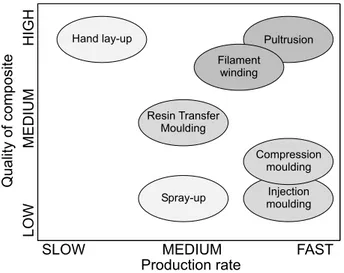
Many different composite manufacturing techniques are available, which differ in the quality of the final product, cost, production rate, achievable size and shape. Indeed, all these factors need to be taken into consideration when the process is selected. In particular, good quality of the resulting composite and high rate of production are usually contrasting needs, as the processes that yield the best results in terms of fibre quantity and placement are usually more time consuming. An exception is pultrusion, which is however suitable only for cylindrical shaped composites. The achievable quality and production rate of some manufacturing processes are reported in Figure 1.4.
Composite manufacturing consists of four phases: impregnation, lay-up, con-solidation and solidification. In impregnation, fibres are thoroughly covered with matrix to ensure a good fibre-matrix interface. Naturally, in this phase matrix viscosity is a key factor. Depending upon the process, dry fibres or fibres al-ready impregnated by the materials supplier (pre-pregs) are used. The lay-up
consists in positioning different layers of reinforcement one on top of the other to make a laminated composite. Each layer (lamina) can be made with a dif-ferent reinforcement and the fibre orientation can vary from one layer to the other. Consolidation is a crucial phase which influences the quality of the final composite: a pressure is applied to remove voids and create the best possible contact between the laminae. Depending on the process, pressure can be applied by hand, with a vacuum pump, in autoclave or press. Finally, solidification fixes the composite shape: it is achieved by resin curing and can last from less than a minute to several hours.
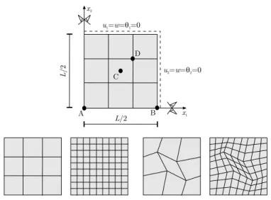
The placement and orientation of the layers are conventionally defined by the laminate’s stacking sequence, or lamination scheme. The laminae, or plies, are listed from the bottom to the top layer and defined by the fibre orienta-tion with respect to an axis associated to the laminate (see Figure 1.5). If not otherwise specified, all laminae have the same thickness. An example of stacking sequence is (0/45/90/ − 45/0). When ply stacking sequence, mate-rial and geometry are symmetric about the laminate midplane, the laminate is symmetric, and can be denoted by only the first half of the stacking se-quence: (0/45/90)s = (0/45/90/90/45/0), or (0/45/ ¯90)s = (0/45/90/45/0) (the bar marks a single central layer). An antisymmetric laminate is a lam-inate whose stacking sequence is antisymmetric about the midplane, for exam-ple (0/45/30/ − 30/ − 45/0). Cross-ply laminates are made up of layers with 0◦ and 90◦ orientation, angle ply laminates include also other stacking angles.
In the following, some composite manufacturing processes are described.
1.3.1
Hand lay-up
Hand lay-up is a very labour intensive technique, whose main advantage is to allow the production of good quality parts which can be large and complex-shaped. It consists in placing the layers on a lower mould by hand and then applying pressure and temperature by means of a vacuum bag or in autoclave to allow resin curing. Two main techniques are included in hand lay-up: pre-preg lay-up and wet lay-up. In the first case, fabrics which are already impregnated with the resin are used, in the second alternate layers of dry fibres and liquid resin are applied using a roller. The use of pre-pregs allows to control more effectively the amount of resin and fibres present in the final composite, thus
a
b
a
b
a
b
Figure 1.5: Laminae fibre orientation
obtaining a material with better properties. On the other hand, pre-pregs are more expensive than dry fibres and resin, require storage below room temper-ature and have a limited shelf life (usually six months to one year). In both cases, the final result strongly depends upon the skills of the laminator.
1.3.2
Spray-up
As hand lay-up, spray-up is an open mould process which allows to produce large and complex-shaped parts. It is a much faster technique, which however gives worse results in terms of composite properties. The fibres and matrix are sprayed on the mould by using a chopper gun, which chops and wets the fibres prior to depositing them on the mould. Once the material has been sprayed, rollers are used to remove entrapped air and the cure is usually done at room pressure and temperature.
1.3.3
Moulding
Moulding processes allow a high production rate as compared to the techniques described up to now. On the down side, their use is usually limited to non
structural parts because of the low properties obtained with moulding com-pounds. An exception is Resin Transfer Moulding (RTM), which is able to produce structural quality parts with a medium production rate. Also, most moulding techniques employ a lower and upper mould, as opposed to the sin-gle side mould used in hand lay-up and spray-up. Although the mould cost increases, closed-mould processes are advantageous because of the low volatile emissions and good surface finish on both sides.
Compression moulding and injection moulding make use of moulding com-pounds as raw materials. These are sheets (Sheet Moulding Compound, SMC) or bulks (Bulk Moulding Compound, BMC) of chopped glass fibres, resin and filler. These usually contain a low percentage of fibres (about 25%) and thus do not yield structural quality material. In compression moulding, a certain quantity of moulding compound (charge) is positioned in the bottom part of the mould, then the top part is closed with a certain velocity. The mould is usually pre-heated to facilitate the resin flow, after a few minutes of cure under heat and pressure the mould is opened and the composite is removed. In injec-tion moulding, the moulding compound is heated and injected through a nozzle into the closed mould. Pressure and temperature are maintained during cure, then after a few minutes the mould is opened and the part removed.
Resin Transfer Moulding differs from the described procedures in that only the resin is injected. Dry fibre preforms are positioned between the top and bottom moulds, then low viscosity resin is injected inside the mould. This allows to control the amount and positioning of fibres and to obtain structural quality parts with a comparatively fast production rate. Naturally, the resin viscosity is a crucial issue in this process. In Vacuum Assisted RTM (VARTM), the resin infiltration and fibre wetting is helped by the presence of void. For very large parts, such as boat hulls, the top mould can be substituted by a vacuum bag. In this case, thickness of the resulting composite is less controllable but the cost of the mould is cut to half. This technique is also known with the name of resin infusion and is a good and cost-effective alternative to wet lay-up when it comes to the manufacturing of large and complex parts.
1.3.4
Pultrusion
Pultrusion is a low cost, high production rate, structural quality technique to produce cylindrical beam-like composites. Fibre rovings are impregnated by passing through a resin bath, then they are pulled through a heated die where they cure and achieve the desired shape. Curing occurs with high temperature and low pressure. The process is continuous, therefore composite beams of any length can be obtained. The disadvantages of this highly automated process are the limited shapes that can be achieved and the impossibility to choose the fibre orientation (unidirectional fibres along the beam axis or, at most, bidirectional fabrics can be used).
1.3.5
Filament winding
Filament winding is also a highly automated process, which yields good per-formance composites. Fibre rovings are passed through a resin bath and then wound over a rotating mandrel at a desired angle. Once the fibre winding is over, the composite is cured at room or high temperature, then the mandrel is extracted. The choice of fibre orientation is improved with respect to pultrusion, even though not every possible orientation can be achieved. As for pultrusion, the main disadvantage of filament winding is the limitation in the shapes that can be achieved (tubular, closed parts).
1.4
Active materials
Due to their coupled behaviour, active materials can be used for sensing and/or actuation purposes. The coupling can be related to intrinsic material charac-teristics, usually at the microstructural level, or to the ‘intelligent’ combination of different traditional materials. A variety of materials display active charac-teristics, thus different classifications are introduced to help identify the most appropriate for the sought application.
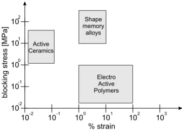
Some classification criteria are discussed here. One possibility, adopted in the following, is to distinguish active materials according to the coupled field (electrical, thermal, magnetic, chemical etc.). Other classifications include the type of material (metal, polymer, ceramic etc.) or the response obtained in terms of force and/or strain. The last classification is particularly useful when
% strain blockingstress[MPa] 10-1 10-2 100 101 102 103 10-2 10-1 100 101 102 Active Ceramics Electro Active Polymers Shape memory alloys
Figure 1.6: Classification of some active materials according to the stress-strain response
choosing a sensor or an actuator for a specific application. Indeed, the order of magnitude of the stress and strain which can be achieved from different active materials is extremely variable, as it can be seen in Figure 1.6. In particular, it is clear from the graph how shape memory alloys are significantly superior to active ceramics and electroactive polymers in both output stress and strain, thus making a good candidate for the creation of active composites.
An overview of some active materials and the principle lying at the basis of their coupled behaviour is given in the following.
1.4.1
Electrical coupling
The most common materials exhibiting electromechanical coupling are piezo-electric materials. The piezopiezo-electric effect consists in an accumulation of elec-tric charges as a consequence of applied stress (direct piezoelecelec-tric effect) or in a deformation generated by an applied electric field (inverse piezoelectric ef-fect). The effect is related to the presence within the material of charged dipoles
whose orientation changes according to the applied electric field. Some crystals naturally display the piezoelectric effect, whose magnitude can be increased by the polarization process. Most piezoelectric materials used in applications are ceramics, but also some polymers are manufactured to display piezoelectric properties. Piezoceramic wafers can develop large forces, however the associ-ated deformations are rather small (of the order of nanometers), therefore more complex configurations, such as stacks or bimorphs, are generally created to enhance the available deformation.
Among the polymers displaying electromechanical coupling, one should in-clude dielectric elastomers. These are devices obtained by placing a layer of very compliant and nearly incompressible dielectric material between two thin compliant electrodes. By applying a current to the electrodes, these tend to get nearer to each other, thus squeezing the dielectric layer which elongates in the perpendicular direction due to the Poisson effect. Some issues related to the fabrication and use of dielectric elastomers are the choice of the dielecric material and the electrodes, which need to be extremely compliant in order not to break during the actuation, and the use of very high voltages, of the order of some kV.
1.4.2
Thermal coupling
All materials exhibit thermomechanical coupling, related mostly to the thermal expansion behaviour. However, in shape memory alloys this coupling is much stronger than in traditional materials and it is related to complex changes in the material microstructure. Shape memory alloys are the subject of Chapter 3 and they are not further discussed here.
1.4.3
Magnetic coupling
Materials exhibiting magnetomechanical coupling include magnetorheological fluids and magnetostrictive materials. Ferromagnetic shape memory alloys also belong to the latter group. Magnetorheological fluids are liquids whose viscosity greatly changes with an applied magnetic field, to the point of becoming viscous solids. Magnetostrictive materials can be deformed via an applied magnetic field, thanks to the orientation of the magnetisation axis. In ferromagnetic
shape memory alloys, different orientation of the martensitic microstructure with an applied magnetic field are responsible for the macroscopic deformation.
1.4.4
Chemical coupling
A new class of active materials whose coupled behaviour is related to chemical reactions are ionic polymers. The actuation mechanism is related to the change in volume of the polymer as it acquires or loses ions in oxidation-reduction reactions. Due to the type of material and the microstructural changes involved, very low forces but extremely large deformations can be achieved as compared to other active materials. The chemical reaction is usually triggered by electrical current, while the polymer is immersed in an electrolytic solution which provides the necessary ions. For this reason, ionic polymers are usually classified as wet, as opposed to piezoelectric polymers or dielectric elastomers, which can work in a dry environment. Recent research work, however, is aimed at devising new ways to provide ions for the chemical reaction, which would allow ionic polymers to operate in air.
Modellazione dei compositi fibro-rinforzati
Negli ultimi anni l’utilizzo dei materiali compositi in applicazioni ad elevata tecnologia `e incrementato in maniera significativa. Lo sviluppo di nuove appli-cazioni, incluse quelle basate su materiali attivi integrati nella struttura, richiede la definizione di strumenti di modellazione semplici ed accurati in grado di de-scrivere il comportamento strutturale di elementi compositi. Per questo, gli strumenti analitici e numerici per la modellazione di tali materiali costituiscono un tema di ricerca molto attivo.
Sono state proposte numerose teorie strutturali per i laminati, molte delle quali descrivono il composito come un elemento di piastra o guscio bidimensio-nale. Le teorie bidimensionali sono in genere semplici e richiedono un numero limitato di parametri, per questo costituiscono una base ideale per lo svilup-po di strategie numeriche quale il metodo degli elementi finiti. D’altra parte, la riduzione di una struttura tridimensionale multistrato ad un singolo strato equivalente porta alla perdita di informazioni, in particolare relative alle tensio-ni lungo lo spessore, che potrebbero rivelarsi cruciali per l’accurata valutazione del comportamento del composito e dei suoi meccanismi di danneggiamento. La formulazione di un modello bidimensionale a partire dalla teoria tridimensiona-le rimuove in parte tatridimensiona-le inconveniente, permettendo di ricostruire a posteriori le tensioni lungo lo spessore. Nella sezione 2.1 vengono derivati alcuni modelli bidimensionali secondo questa logica e viene discussa la procedura analitica per la ricostruzione delle quantit`a tridimensionali.
Una volta scelto un modello analitico, `e necessario definire procedure nu-meriche accurate e computazionalmente efficienti. Nella sezione 2.2 si propone un nuovo elemento finito basato sulla teoria al primo ordine, definita nella se-zione 2.1. Una formulase-zione ibrida agli sforzi ed un’accurata selese-zione delle approssimazioni per sforzi e spostamenti permettono di costruire un elemento semplice, stabile e computazionalmente efficiente, preparando la strada per la ricostruzione delle quantit`a tridimensionali.
La procedura analitica di ricostruzione, descritta nella sezione 2.1, non `e automaticamente applicabile a partire da una soluzione bidimensionale appros-simata. Nascono infatti alcuni problemi riguardanti la convergenza delle quan-tit`a ricostruite ed il soddisfacimento delle condizioni al contorno del problema tridimensionale. Nella sezione 2.3 si definisce una strategia generale per la
rico-struzione delle tensioni lungo lo spessore a partire da soluzioni bidimensionali agli elementi finiti.
La modellazione dei materiali compositi richiede la conoscenza delle pro-priet`a elastiche del laminato, difficili da determinare con i metodi sperimentali tradizionali. Le tecniche numerico-sperimentali basate sulla misura delle fre-quenze naturali del composito rappresentano una valida alternativa ai metodi statici tradizionali. Nella sezione 2.4 sono messe a confronto alcune tecniche operanti in un contesto bayesiano, concentrandosi in particolare sull’influenza dei valori iniziali sul risultato dell’operazione di stima.
Chapter 2
Modelling of
fibre-reinforced composites
Recently, the use of fibre-reinforced composites in high technology applications has dramatically increased. The development of new composite applications, including those based on embedded active materials, has engendered the need for simple and accurate modelling tools to describe their structural behaviour. In particular, both analytical and numerical tools for composite modelling are the subject of ongoing research.
Many laminate theories have been proposed, a number of them describing the composite as a two-dimensional plate or shell structure (see, for example, Carrera, 2002; Carvelli and Savoia, 1997; Ghugal and Shimpi, 2002; Reddy, 1997). Two-dimensional theories are generally simple and require a limited number of parameters, thus they are an ideal basis for the development of nu-merical solution strategies like the finite element method. On the other hand, reducing a three-dimensional multilayered composite structure to an equiva-lent single layer leads to a loss of information which might be crucial for the accurate evaluation of the composite behaviour and failure modes. For this reason, it is convenient to formulate the two-dimensional model as descending from a parent three-dimensional theory. This allows to reconstruct some of the three-dimensional quantities by post processing the two-dimensional solution. In Section 2.1, the outlined derivation is carried out for various two-dimensional
theories and the post processing allowing to reconstruct the three-dimensional quantities is discussed.
Once the analytical model has been established, accurate and computation-ally efficient numerical solution procedures need to be defined. Focusing on the finite element method, in Section 2.2 a new finite element is proposed, based on the First-order Shear Deformation Theory established in Section 2.1. A hybrid stress formulation and a careful selection of the displacement and stress approx-imations leads to a simple, stable and computationally efficient element and paves the way for the numerical post processing of the two-dimensional finite element solution.
Reconstruction of three-dimensional quantities starting from approximate two-dimensional solutions, such as those obtained via finite elements, is not straightforward. Indeed, problems arise concerning the convergence of the re-constructed quantities and the satisfaction of three-dimensional boundary condi-tions. A general strategy for the reconstruction of three-dimensional quantities starting from a two-dimensional finite element solution is defined in Section 2.3. Composites modelling requires the knowledge of the laminate material prop-erties, which are not easily determined via traditional testing methods. For this reason, Section 2.4 deals with the analysis and comparison of numerical-experimental techniques for the estimation of the laminate material properties from natural frequency data.
2.1
Analytical modelling of laminated plates
The modelling of complex and multi-phase materials such as composites can be approached from a variety of points of view. In particular, it is possible to distinguish between micromechanical and macromechanical approaches. In the first case, the different constituents (fibres and matrix) are modelled separately and their interaction is taken into consideration, while in the second some ho-mogenisation technique is employed to reduce the overall composite behaviour to that of a homogeneous equivalent continuum.The two approaches are fundamentally different in complexity and capability to model the behaviour of composite materials. Micromechanical approaches, though complex, are able to reproduce phenomena, such as fibre slipping, ma-trix cracking and other mechanisms involving the different constituents, which
cannot be observed in the context of macromechanical models. These, on the other hand, are simple and require the introduction of a limited number of vari-ables, thus they are suitable to model large scale structures with a reasonable computational effort.
A bridge between the two strategies is constituted by the so called multiscale techniques. These strategies allow to jump back and forth between the micro and macromechanical approaches, passing information between the two worlds and observing each phenomenon at the appropriate scale. For the use of multiscale techniques in the analysis of laminated composites, see Ladev`eze et al. (2006). In the following, only macroscale models are taken into consideration.
Macromechanical approaches, as already pointed out, model each lamina as a homogeneous material with non isotropic material properties. Low symmetry material models include monoclinic materials, having a single plane of material symmetry, and orthotropic materials, which present three orthogonal planes of material symmetry. Because of the presence of fibres aligned along one or two orthogonal directions, unidirectional and woven fabric laminates are usually modelled as orthotropic materials.
Once the lamina has been established as a homogeneous anisotropic con-tinuum, there still remain various choices on the modelling of the laminated composite. One can distinguish between Equivalent Single Layer (ESL) and layerwise theories. ESL theories are discussed in detail in the following section, a brief account on the idea behind layerwise theories is given here.
As the name suggests, layerwise theories model each lamina, or layer, as a plate (or shell) structural element, then impose interlaminar continuity con-ditions on the displacements and transverse stresses, thus joining the laminae together. In particular, displacements are assumed to be C0-continuous in the
thickness, with discontinuous derivatives between the laminae, allowing for the presence of discontinuous strains. On the other hand, transverse stresses are set to be continuous between the laminae: this is possible because of the change in constitutive properties, due to the change in material or in the lamina fibre orientation. Partial layerwise theories account for continuous transverse shear stresses across laminae, while full layerwise theories include also the continuity of transverse normal stress. Depending on the assumptions, each layerwise the-ory yields a different approximation of a full three-dimensional thethe-ory, always satisfying interlaminar continuity conditions and thus allowing to properly
ac-count for transverse shear and transverse normal effects. These are necessary to accurately model the behaviour of thick laminates and to predict phenomena occurring at the lamina level, such as delamination.
2.1.1
Equivalent Single Layer theories
Equivalent Single Layer theories model laminated plates as an equivalent single lamina with complex constitutive properties. They are fully two-dimensional models, which are derived by generalising the theories already developed for single layer plates. As such, many ESL theories are present, each originated from a different single layer plate theory and so making different choices as regards the admissible displacement field.
Common to all ESL theories is the loss of interlaminar continuity of trans-verse stresses. Indeed, in these models the displacement field typical of a single layer plate is postulated for a laminate, which is non homogeneous in the thick-ness direction. This discrepancy with respect to the three-dimensional descrip-tion is a drawback of ESL theories with respect to layerwise models, however it can be partially overcome by considering the ESL theory as descending from a parent three-dimensional theory. Indeed, if a structural theory is postulated directly, all information which is not contained in the assumed description is lost. On the other hand, if the theory is established as descending from a par-ent three-dimensional theory some of this information can be reconstructed in the post processing of the structural theory results.
Plate theories can be derived by considering a three-dimensional body with special shape and partitionability (plate-like body) and setting some restric-tions on the admissible deformarestric-tions. Via the theory of constrained continua, the three-dimensional compatibility, constitutive and equilibrium equations are written based on the defined kinematic ansatz, then the equations for the two-dimensional flat body (plate) can be derived in different ways (DiCarlo et al., 2001; Teresi and Tiero, 1997). Later, once the two-dimensional problem is solved, post processing considerations allow to reconstruct some of the quanti-ties that have been lost in the three-dimensional to two-dimensional mapping.
In particular, crucial to the soundness of the procedure is the concept of reactive stresses (Lembo and Podio-Guidugli, 2007). If the ansatz on the ad-missible displacements is regarded as internal constraints to the plate-like body,
x z p(+) p( ) ¶W W kthlamina d n b zk zk -1 O
Figure 2.1: Plate-like body
the three-dimensional stress field σ decomposes into an active and a reactive part:
σ = σA+ σR. (2.1) The active part σAis related to the deformation via constitutive equations; the
reactive part σRis given the role of maintaining the constraints, while doing no
work for each admissible deformation. Thus, reactive stresses can be regarded as reactions to the constraints. The null-working condition can be stipulated pointwise or partwise, with resulting integral conditions corresponding to the peculiar partitionability in plate-like subdomains. It can be easily realised that, when the three-dimensional plate-like body is mapped into the two-dimensional plate model, only active stresses come into play. Thus, σA is constitutively
determined by the solution of the plate problem, while σR can be selected a
posteriori by enforcing the three-dimensional equilibrium equations, in order to improve the approximation the three-dimensional stress field σ.
In the following, the outlined derivation is briefly carried out for some of the most common plate theories, introducing a common notation. They include the Classical Laminated Plate Theory (CLPT), which is the laminated plate equivalent of Kirchhoff-Love single layer plate theory; the First-order Shear Deformation Theory (FSDT), based on Reissner-Mindlin assumptions; a general higher-order theory and the third-order theory proposed by Reddy (1984).
A plate-like body is a three-dimensional body whose reference shape is a right cylinder of modest height h (Figure 2.1). Let (x1, x2, z) = (x, z) denote the
Material coordinate system (lamina)
Problem coordinate system (laminate) x 1 x 2 z a b c
Figure 2.2: Material and problem coordinate systems
coordinates of a point with respect to a Cartesian system with the z-axis parallel to the generators of the cylinder. Notice that the problem coordinate system (x1, x2, z) is in general different from the material coordinate system (a, b, c)
associated to each lamina. The latter is related to the material symmetry, as depicted in Figure 2.2. The cylinder cross section at z = 0 is denoted by Ω, with boundary ∂Ω, while the top and bottom surfaces at z = ±h/2 are denoted by Ω(+)and Ω(−), respectively. The typical material fibre is denoted by F and
its undeformed configuration is defined by (x = const., −h/2 ≤ z ≤ h/2). Body forces (bx, bz) and surface loads
³
p(+)x , p(+)z ´
,³p(−)x , p(−)z ´
are prescribed inside the body and on the top and bottom surfaces, respectively.
Classical Laminated Plate Theory
In the Classical Laminated Plate Theory, the following kinematic ansatz is made on the admissible displacement field d:
∇2
zd = 0, (2.2)
∇zd · k = 0, (2.3)
∇xdz = −∇zdx, (2.4) with k being the unit vector normal to Ω and ∇z and ∇x the derivatives with respect to z and (x1, x2) respectively. Condition (2.2) states that material fibres
F remain straight after the deformation, while (2.3) precludes fibre extension.
Finally, condition (2.4) imposes the orthogonality of the fibres to the deformed middle surface of the plate.
Due to the constraints, d assumes the form: d = · u (x) − z∇xw (x) w (x) ¸ , (2.5)
where u (x) and w (x) are the in-plane and transverse displacements of a point belonging to the Ω. Note that the three-dimensional displacement field of the plate-like body is fully defined once u and w are known. These quantities, called the generalised displacements, are function only of the position of the fibre F, thus the fibre is the minimum unit for the two-dimensional model. The same is true in the other plate theories presented in the following.
The three-dimensional strain tensor ε can be derived from the compatibility equations: ε = · e 1 2γ 1 2γT εz ¸ , ε = ∇(s)d, (2.6)
where ∇(s) = sym grad is the compatibility operator, e is the in-plane strain
tensor, γ the transverse shear strain vector and εz the transverse normal strain. These quantities can be expressed by introducing the generalised strains, which are once again function only of the fibre position x. Introducing the expression for the displacement field, Equation (2.5), into Equation (2.6) we obtain
e = ∇(s)
x u − z∇(s)x (∇xw) = µ + zχ, (2.7)
γ = ∇xw − ∇xw = 0, (2.8)
εz = ∇zw = 0, (2.9)
where µ (x) and χ (x) are the membranal strains and the curvatures, respec-tively. The physical meaning of the generalised strains is clarified by Figure 2.3, which shows the deformation of a small element under the effect of each generalised strain component.
Note that the transverse normal strain εz is null as required by condition (2.3). Also, due to condition (2.4), transverse shear strains γ are null in the CLPT. This is a major drawback of this theory, since shearing effects are negli-gible only for thin plates. The problem is emphasised when modelling laminated composite plates, whose anisotropy renders shear effects even more significant than in single layer isotropic plates.