A
A
l
l
m
m
a
a
M
M
a
a
t
t
e
e
r
r
S
S
t
t
u
u
d
d
i
i
o
o
r
r
u
u
m
m
–
–
U
U
n
n
i
i
v
v
e
e
r
r
s
s
i
i
t
t
à
à
d
d
i
i
B
B
o
o
l
l
o
o
g
g
n
n
a
a
DOTTORATO DI RICERCA IN
INGEGNERIA STRUTTURALE E IDRAULICA
Ciclo XXIII
Settore scientifico-disciplinare di afferenza: ICAR 02
EXPERIMENTAL AND NUMERICAL ANALYSES ABOUT THE
EFFICIENCY OF FLOW THROUGH DEVICES FOR THE SEDIMENT
CONTROL IN URBAN RUNOFF
Presentata da:
CICCARELLO ANNALISA
Coordinatore Dottorato
Relatore
Chiar.mo Prof. Ing. Erasmo VIOLA
Chiar.mo Prof. Ing.Sandro ARTINA
“A little experience often upsets a lot of theory.” Cadman
CONTENTS
ABSTRACT 1
1. INTRODUCTION: STORMWATER QUALITY AND SEDIMENT REMOVAL MEASURES 3
1.1. Sommario 3
1.2. Introduction 5
1.3. Impacts of urbanization on runoff 7
1.3.1. Increased runoff 7
1.3.2. Runoff quality 8
1.4. Stormwater quality control measures 15
1.5. Regulations 21
1.5.1. Italian regulations 21
1.5.2. American regulations 22
1.6. The importance of sediments removal 25
1.6.1. Sedimentation process 25
1.7. Objectives of the study 30
1.8. References 33
2. ROADSIDE GULLY POTS: EXPERIMENTAL TESTS AN NUMERICAL MODEL APPLICATION 37
2.1. Sommario 37
2.2. Introduction 39
2.2.1. Gully pots overview 39
2.3. Previous experiences 43
2.3.1. Laboratory studies 43
2.4. Objectives 45
2.5. Materials and methodology 45
2.5.1. Experimental setup 45
2.5.2. Gradation and injection 47
2.5.3. Testing procedure and mass recovery 49
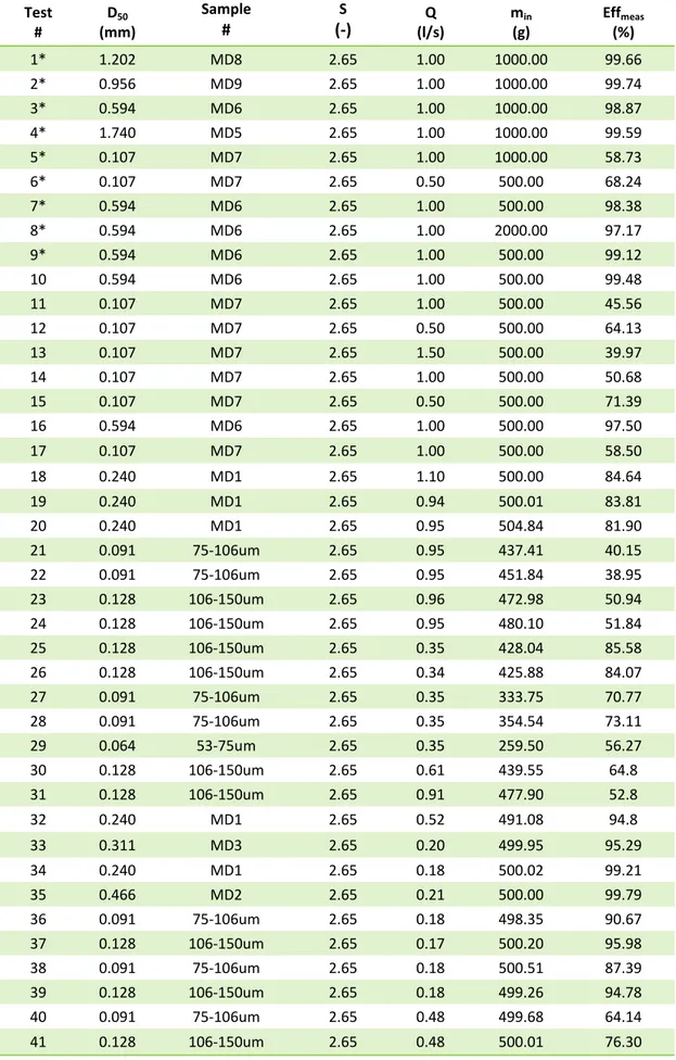
2.6. Experimental runs and results 50
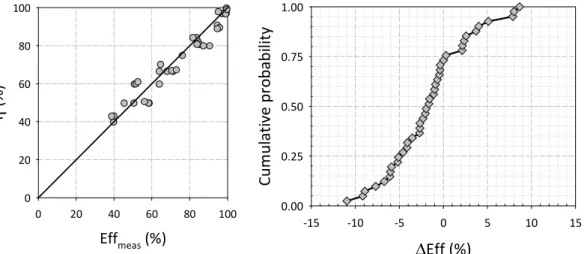
2.7. Comparison of modeled and measured PM separation 53
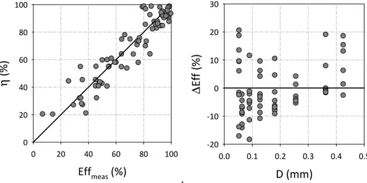
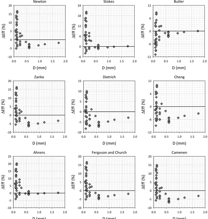
2.8. Influence of settling velocity formulation 58
2.9. Conclusions 68
2.10. References 70
3. HYDRODYNAMIC SEPARATORS:PM SEPARATION EFFICIENCY AND RESIDENCE TIME
DISTRIBUTION STUDIES 72
3.1. Sommario 72
3.2. Introduction 74
3.2.1. Hydrodynamic separator overview 75
3.3. Description of the device and its purpose 78
3.4. Objectives 80
3.5. Materials and methodology 80
3.5.1. Experimental setup 80
3.5.2. Description of equipment and components 81
3.5.3. Data acquisition and management 82
3.5.4. NJCAT gradation preparation and injection methodology 82 3.6. Testing procedure: sampling methodology and mass recovery 84
3.7. Laboratory analyses 85
3.8. Efficiency calculation and mass balance 86
3.9. Experimental runs and results 87
3.10. Comparison of a SOR modeled and measured PM separation for the hydrodynamic
separator 95
3.11. Residence Time Distribution curves 97
3.11.1. Factors leading to non-ideal-flow in reactors 101
3.13. Conclusions 113
3.14. References 115
3.15. Appendix of US Silica sand product data 118
3.16. Appendix of SCS Unit Hydrograph 122
3.17. Appendix of YSI calibration for RTD analysis 123
4. CLARIFIER: COMPARISON BETWEEN THE EFFICIENCIES OF TWO DIFFERENT CONFIGURATIONS AND
TURBIDITY MEASUREMENTS 124 4.1. Sommario 124 4.2. Introduction 127 4.2.1. Clarifiers overview 128 4.2.2. Sedimentation theory 129 4.3. Objectives 131
4.4. Materials and methodology 132
4.4.1. Experimental setup 132
4.4.2. Data acquisition and management 133
4.4.3. Gradation and injection 134
4.5. Testing procedure: sampling methodology and mass recovery 134
4.6. Laboratory analyses 136
4.7. Efficiency calculation and mass balance 137
4.8. Experimental runs and results 138
4.8.1. Description of the two configurations 138
4.8.2. Hydrographs 140
4.8.3. Experimental design for the clarifiers (linear and crenulated
configuration) 140
4.8.4. Results 142
4.9. Comparison of a SOR modeled and measured PM separation for the clarifier 146
4.10. Turbidity measurements 148
4.10.1. Bias in optical methods 150
4.11. Turbidity monitoring: literature review 150
4.12. Methodology and instruments 156
4.12.1. Turbidity 156
4.12.2. SSC measurements 158
4.13. Results and discussion 160
4.14. Conclusions 165
4.15. References 167
4.16. Appendix of US Silica sand product data 171
CONCLUSIONS 172
Abstract
As land is developed, the impervious surfaces that are created increase the amount of runoff during rainfall events, disrupting the natural hydrologic cycle, with an increment in volume of runoff and in pollutant loadings. Pollutants deposited or derived from an activity on the land surface will likely end up in stormwater runoff in some concentration, such as nutrients, sediment, heavy metals, hydrocarbons, gasoline additives, pathogens, deicers, herbicides and pesticides. Several of these pollutants are particulate-bound, so it appears clear that sediment removal can provide significant water-quality improvements and it appears to be important the knowledge of the ability of stromwater treatment devices to retain particulate matter. For this reason three different units which remove sediments have been tested through laboratory. In particular a roadside gully pot has been tested under steady hydraulic conditions, varying the characteristics of the influent solids (diameter, particle size distribution and specific gravity). The efficiency in terms of particles retained has been evaluated as a function of influent flow rate and particles characteristics; results have been compared to efficiency evaluated applying an overflow rate model. Furthermore the role of particles settling velocity in efficiency determination has been investigated. After the experimental runs on the gully pot, a standard full-scale model of an hydrodynamic separator (HS) has been tested under unsteady influent flow rate condition, and constant solid concentration at the input. The results presented in this study illustrate that particle separation efficiency of the unit is predominately influenced by operating flow rate, which strongly affects the particles and hydraulic residence time of the system. The efficiency data have been compared to results obtained from a modified overflow rate model; moreover the residence time distribution has been experimentally determined through tracer analyses for several steady flow rates. Finally three testing experiments have been performed for two different configurations of a full-scale model of a clarifier (linear and crenulated) under unsteady influent flow rate condition, and constant solid concentration at the input. The results illustrate that particle separation efficiency of the unit is predominately influenced by the configuration of the unit itself. Turbidity measures have been used to compare turbidity
with the suspended sediments concentration, in order to find a correlation between these two values, which can allow to have a measure of the sediments concentration simply installing a turbidity probe.
1.
Introduction: stormwater quality and sediment removal
measures
1.1.
Sommario
Il continuo incremento delle aree urbanizzate e la necessità di tutelare i corpi idrici riceventi richiedono un’ampia comprensione dei fenomeni di accumulo e dilavamento del materiale particolato presente sulle superfici impermeabili, nonché delle caratteristiche dello stesso. È infatti noto che buona parte delle sostanze inquinanti presenti sulle superfici urbane aderisce alle particelle solide, in quantità e con modalità che variano in base alla granulometria delle particelle stesse. Diverse sono le misure che si possono adottare per trattare le acque di pioggia: dalle best managment practices, come trincee filtranti, bacini di ritenzione, bacini per la fitodepurazione, ecc., a soluzioni tipiche del nostro Paese come le vasche di prima pioggia.
Tra le varie modalità di rimozione delle particelle solide, la più semplice è la sedimentazione; l’efficienza nel trattenere il materiale solido è funzione delle caratteristiche del materiale stesso (granulometria e peso specifico) e del funzionamento del manufatto. Le attività sperimentali sia di laboratorio sia di campo sono ancora oggi uno degli strumenti più utilizzati per determinare quali grandezze influiscono sulla funzionalità idraulico-ambientale di tali unità, al variare delle caratteristiche degli eventi di pioggia e del materiale dilavato dalla sede stradale. Inoltre le prove sperimentali forniscono dati utili all’elaborazione di modelli sofisticati, che permettono di fare previsioni e fornire indicazioni sulle tempistiche di manutenzione di tali manufatti. Con tale scopo nella presente tesi sono stati testati tre diversi manufatti, caratterizzati dall’essere dispositivi in continuo, ossia che trattano tutta la portata in ingresso; i manufatti oggetto di studio sono i seguenti: una caditoia stradale, un separatore idrodinamico e una vasca di sedimentazione. Essi risultano caratterizzati da
geometria e capacità notevolmente differenti tra loro, ma funzionano tutti sfruttando il principio della gravità. Le prove sperimentali sono state condotte in condizioni di portata sia costante che variabile e utilizzando materiale solido in ingresso caratterizzato da granulometrie di vario tipo (materiale solido sia monogranulare sia assortito). I risultati sperimentali sono stati confrontati con quelli che si ottengono dall’applicazione di formule sintetiche desunte da letteratura. Tali risultati, inoltre, possono essere utilizzati per applicazioni future come parametri di calibrazione di modelli più complessi.
1.2.
Introduction
Sediments and dusts transported and stored in the urban environment are well known to provide high loadings of solid particles to receiving waters; for this reason urban runoff has been identified as a major contributor to the degradation of water bodies. Studies conducted by Pitt, et al.(1995) characterized the toxic contributions to urban runoff from sources such as roofs, parking areas, storage areas, streets, loading docks, vehicle service areas, and landscaped areas. From this investigation it turned out that roof, vehicle service area and parking lot runoff samples had the greatest organic toxicant detection frequencies and the highest levels of detected metals. Moreover these areas are particularly subjected to spills and leaks of automotive products and exhaust emissions from frequently starting vehicles. The organic compounds are associated especially with automobile and pesticide use, or are associated with plastics; heavy metals present in runoff water are originated by automobile use activities, including gasoline combustion, brake lining, fluids (brake fluid, transmission oil, anti-freeze, grease, etc.), undercoatings, and tire wear (Durum 1974; Koeppe 1977; Rubin 1976; Shaheen 1975; Solomon and Natusch 1977; Wilber and Hunter 1980).
The transport of this type of constituents is controlled by dry depositional processes (Wu et al. 1998), physiochemical interactions between water and the various phases of solids, suspension of constituents by turbulent water flow, and aquatic chemistry (Deletic and Maksimovic, 1998). Many deterministic rainfall-runoff models, to determinate runoff rate and volume, have been used to design hydraulic structures to convey rainfall runoff. On the contrary, due to the complexity of the phenomenon of transport and dispersion of pollutant during rainfall events, the history of pollutant transport modeling is relatively brief (Tomanovic 1990; Bertrand-Krajewski et al. 1993; Phan et al. 1994) and it is possible to state that a deterministic model reliable in the prediction of the pollution discharge does not yet exist (Bertrand-Krajewski et aI. 1993). Rainfall-runoff simulation models consider some processes in the pollution generation and runoff process, like the build-up on impervious surfaces during dry periods, the wash-off during rainfall events, the conveyance in structures as gully pots, catch basins, etc. This suggests that the runoff phenomena is very complex; its modeling is essentially a problem of fluid mechanics controlled by the rainfall rate. As
atmospheric deposition processes (availability); chemical and physical interactions between water and solids (mobilization); hydrodynamic interactions between turbulent water flow and settleable solids (transport); and chemistry (mobilization and transformation). The contribution of individual components of the urban hydrological cycle to the transport and storage of particles and heavy metals has been studied: gully pots (Morrison et al., 1988), street and road surfaces (Xanthopoulos and Hahn, 1993; Gibson and Farmer, 1984; Hamilton et al., 1984), etc.
The wash-off and transport of solids cause a double problem: the presence of sediments in downstream sewers (engineering issue); pollution of downstream water bodies (environmental issue). Accumulations of sediments within pipelines and other network components can result in operational difficulties, like restrictions that reduce the passage of flows, premature overflows, and the inevitable pollution of watercourses (Fraser and Ashley, 1999). Sediment deposition in sewers is extremely widespread, because of the wide range of types of solids which enter the sewer system, and the intermittent and highly variable nature of inflow regimes. The use of sediment interceptors within sewer systems or downstream of stormwater intakes represents one way of alleviating these problems. Regarding pollutants, any pollutant deposited or derived from an activity on the land surface ends up in stormwater runoff in some concentration. However, there are certain pollutants and activities that are consistently more likely to result in degradation of a stream or receiving water, as previously stated. The direct effects of these pollutants on receiving waters are often a function of the size of the receiving water and the sensitivity of the inhabiting organisms. Sensitive species such as trout and stoneflies may be more susceptible to a range of pollutants than more pollution-tolerant organisms such as the black-nosed dace or certain leeches. However, assessing a toxic response from stormwater requires analyses that consider variable concentrations with variable durations of exposure. Certain pollutants even at low levels are of greater concern when receiving waters have specific beneficial uses such as swimming or fishing. Drinking water reservoirs require more sensitive
1.3.
Impacts of urbanization on runoff
1.3.1.
Increased runoff
The porous and varied terrain of natural landscapes like forests, wetlands, and grasslands traps rainwater and snowmelt and allows them to filter slowly into the ground. Development and urbanization can change the hydrologic response of the watershed in an impressive way. Considering the environment conditions before and after the development, it is evident how the vegetation has a fundamental role in the interception of precipitation; indeed the rainfall water can be directly intercepted by the vegetation, or can be infiltrated into the ground. Urbanization can remove this beneficial vegetation, replacing it with impervious surfaces, like roofs, parking lots, roads, thereby reducing the site’s pre-developed evapotranspiration and infiltration rates. In addition, construction activities may also compact the soil and diminish its infiltration rate, resulting in increased volumes of stormwater runoff from the development site. Impervious areas discharge rainfall water directly to gutters, channels, and sewer systems; this water transfer occurs more quickly than vegetated conveyances; this shortening of the travel time quickens the rainfall-runoff response of the site, causing faster and higher pick flow in downstream waterways than under natural or pre-developed site conditions. These increases can create downstream flooding and erosion problems and can increase the quantity of sediment and other pollutants in the waterways. With the increasing of the impervious areas the opportunities for the runoff to be infiltrated by natural surfaces decrease and the groundwater recharge decreases as well. Reduced base flows and increased peak flows during wet weather produce greater fluctuations between normal and storm flow rates, which can negatively impact the health of biological communities that depend on these base flows.
Figure 1.1 - Relationship between impervious cover and surface runoff: impervious cover in a watershed results in increased surface runoff and a reduction in infiltration (by the Federal
Interagency Stream Restoration Working Group – FISRWG)
1.3.2.
Runoff quality
Land development causes an increase in runoff volume and pollutant concentrations. On the impervious areas the accumulation of a variety of pollutants from the atmosphere, fertilizers, animal wastes, and leakage and wear from vehicles occurs. Pollutants can include metals, suspended solids, hydrocarbons, pathogens, and nutrients. Common pollutants found in stormwater runoff are shown in table 1.1.
Pollutant Typical Concentration
Total Suspended Solids (a) 80 mg/l
Total Phosphorus (b) 0.3 mg/l
Total Nitrogen (a) 2.0 mg/l
Total Organic Carbon (d) 12.7 mg/l
Fecal coliform bacteria (c) 3600 MPN/1000 ml
E. Coli bacteria (c) 1450 MPN/100 ml Petroleum hydrocarbons (d) 3.5 mg/l Cadmium (e) 2 µg/l Copper (a) 10 µg/l Lead (a) 18 µg/l Zinc (e) 140 µg/l Chlorides (f) 230 mg/l Insecticides (g) 0.1 to 0.2 µg/l
Solids and floatables
Solids and floatables are one of the most concerning surface water pollutant. They are wastes or debris floating or suspended; these materials include debris such as bottles, jars, cans, paper bags, newspapers, plastic containers and wrappings, leaves, branches. Solid/floatable materials are wastes that have been disposed of either on land or directly into stormwater conveyances and during rainfall event they are transported by runoff to receiving waters. Solid/floatable material can create odors, aesthetic problems, and even toxic or corrosive gases that can emanate from bottom mud deposits.
Suspended solids are of concern in runoff because they are able to clog infiltration areas (Crites, 1985) and treatment devices that use infiltration. During percolation suspended and colloidal particles are trapped by pores of small diameter. Coarse texture soils allow deep penetration of these particles and if the water table is close to the surface, the suspended particle enter the aquifer and increase the turbidity and pollutant content of the groundwater (Bouwer, 1985; Treweek, 1985).
Sediments
Sediment is one of the most significant pollutants created by development and transferred by runoff. Sediments consist largely of soil materials eroded from uplands as a result of natural processes and human activities. The greatest sediment loads are exported during the construction phase of land development. Sediment and other nonpoint source pollution from agricultural sources is also a major contributor to water quality problems. High concentrations of suspended sediment in streams and lakes cause many adverse consequences (increased turbidity, reduced light penetration, …). Solids also enter the runoff stream from vehicle emissions, vehicle tire, engine and brake wear, as well as through pavement wear and atmospheric deposition. Sediment is also an efficient carrier of toxins and trace metals. Once deposited, pollutants in these enriched sediments can be remobilized under suitable environmental conditions and threaten benthic life.
Solids in storm water runoff are classified using various methods, mostly as a function of size. Total solids (TS) encompass all solids found in runoff, both suspended and dissolved. Total suspended solids (TSS) and total dissolved solids (TDS) are separated by what does and does not pass through a 0.45 µm filter (APHA, 1998). A PSD analysis further
categorizes solids into size ranges. The American Association of State Highway and Transportation Officials (AASHTO) divide size classes for solids into gravel, sand, silt, and clay. Solids larger than 2000 µm are referred to as gravel, between 75 and 2000 µm as sand, 2 and 75 µm as silt, and less than 2 µm as clay (Das, 1998). The sizes of particles in storm water runoff can significantly affect various physical and chemical processes. Fine particles may agglomerate, causing PSD to vary along the longitudinal path of storm water runoff (Minton, 2002). Larger particles settle faster than smaller particles. This settling mechanism affects the relative concentrations of different sizes of particles depending on runoff velocity and depth of flow.
Dissolved solids refer to any minerals, salts, metals, cations or anions dissolved in water. This includes anything present in water other than the pure water molecule and suspended solids. In general, the total dissolved solids concentration is the sum of the cations (positively charged) and anions (negatively charged) ions in the water. Parts per million (PPM) is the weight to weight ratio of any ion to water. Some dissolved solids come from organic sources such as leaves, silt, and industrial waste and sewage. Other sources come from runoff from urban areas, and fertilizers and pesticides used on lawns and farms. Dissolved solids also come from inorganic materials such as rocks and air that may contain calcium bicarbonate, nitrogen, iron, phosphorous, sulfur, and other minerals. Many of these materials form salts, which are compounds that contain both a metal and a nonmetal. Salts usually dissolve in water forming ions; water may also pick up metals such as lead or copper as they travel through pipes used.
Suspended solids are small solid particles, which remain in suspension in water as a colloid or due to the motion of the water. Generally the amount of particles that suspend in a sample of water is called total suspended solids (TSS). It is used as one indicator of water quality. Suspended solids are important as pollutants and pathogens are carried on the surface of particles. The smaller the particle size, the greater the surface area per unit mass of particle, and so the greater the pollutant load that is likely to be carried. To remain
Nutrients
Phosphorus and nitrogen are nutrients used by plants during photosynthesis. In general, undeveloped land produces relatively few nutrients; agricultural, residential, industrial, and commercial areas produce more nutrient loadings. In rural and residential areas, substantial amounts of nutrients originate from commercial fertilizers, manure from livestock feeding operations, or dairy farming. Pet wastes contribute nutrients to runoff in residential areas. Detergents and raw sanitary waste also contribute to nutrient loading. Highway runoff also contains phosphorous from motor oils, fertilizers, …. The action of phosphates and nitrates can be quite different. Although both can be transported by groundwater, phosphorus often combines with fine soil particles and remains locked in the soil until it is either utilized by plant life or eroded away with the soil. In the latter case, the phosphorus will flow along with the soil particles as suspended sediment. Nitrates in the soil remain much more soluble. During rainfalls, nitrates may pass below the root zone into the groundwater. This movement of nitrates into groundwater may cause a public health hazard. Under normal conditions, phosphorus and nitrogen are not generally regarded as problem chemicals. However, in excessive amounts, phosphorus and nitrogen present a problem by over-stimulating plant growth within the aquatic environment.
Pesticides
Pesticides are toxic substances, used routinely for agricultural purposes and in residential and commercial property maintenance to affect specific unwanted organisms. Pesticides are mostly found in dry weather flows from residential areas (Pitt and McLean, 1986) and have been related in some locations to the amount of impervious cover and to the distance the runoff must travel before infiltration (Lager, 1977; Pruitt et al., 1985; Butler, 1987; German, 1989; Domagalski and Dubrovsky, 1992; Wilson et al., 1990). These substances can produce toxic effects on ecosystems and human life by contaminating soil, water, and air. Numerous acute and chronic effects on humans and other organisms are associated with pesticide exposure. Pesticides are carried in stormwater from application sites by becoming dissolved or suspended in runoff or by binding to particulate matter carried in runoff. These pesticides can contaminate surface or groundwater through infiltration devices or overflow. The fate and transport of pesticides are dependent on their
physical and chemical properties and their chemical interactions with the environment. Some pesticides are highly soluble in water and are easily flushed into aquatic ecosystems or groundwater. These substances reach groundwater when their residence time in soils is less than the time required to filter them or biologically or chemically convert them (Jury et al., 1983). Pesticides with low solubility may accumulate in sediments by adhering to particulate matter. Adsorption and absorption increase with the amount of organic matter present. These factors and the resistance to degradation of certain pesticides increase the persistence of these substances in the environment.
Metals
Concentrations of metals found in water can have adverse effects upon public health as well as upon aquatic biota: lead, which is often used as an indicator for other toxic pollutants in stormwater, can be harmful or deadly for human and aquatic life; zinc, although not harmful to humans at concentrations normally found in stormwater, can be deadly for aquatic life; cadmium can bio-accumulate in an ecosystem, soil microorganisms are especially sensitive to it, and it is harmful to human health; chromium damages fish gills, causes birth defects in animals, and is also dangerous to human health; mercury is a neurotoxin that bio-accumulates.
Some metals bind to soils and organic matter and are transported in sediment, while other metals dissolve in water. Rainwater is naturally slightly acidic, which increases its ability to dissolve heavy metals and compounds the health and environmental effects of stormwater runoff from urban areas. The transportation system is a primary source of metals in stormwater runoff to urban streams and groundwater. Cadmium, copper, cobalt, iron, nickel, lead and zinc are deposited into the environment by vehicle exhaust, brake linings, and tire and engine wear. They accumulate on roads, waiting to be washed into storm drains with the next rainfall. Pollutant concentrations in roadway runoff are positively correlated with traffic volume: all cars, even the cleanest vehicles, shed small amounts of
Figure 1.2 - Estimated contributors of various sources of metals in urban residential stormwater runoff (brick buildings); total loadings: Pb = 0.069 kg/ha/yr, Cu = 0.038 kg/ha/yr, Cd = 0.0012
kg/ha/yr, Zn = 0.646 kg/ha/yr (Davis et al., 2001)
Road Salt
Road salt is commonly used in order to melt snow and ice. During rainfall events precipitation falling on salted surfaces creates runoff containing dissolved salt, which has the potential to compromise vegetation, water quality and the aquatic ecosystem. Indeed the convey of dissolved salt by runoff can contaminate ground and surface waters, which may render them unusable or require expensive treatment procedures, since the increase in sodium chloride concentrations create displeasing drinking water and interfere with pristine manufacturing processes. Because of salt’s long residence time, salt water often tends to build up concentration in groundwater. The input of high concentrated saline water into fresh water lakes can retard springtime mixing. The density of the bottom layer of water increases, thereby overriding the normal thermal density gradients responsible for vertical
bottom dwelling organisms. Increased salt loading to bays and estuaries can alter natural saline concentrations and disrupt shellfish reproduction and fish spawning. Aside from contaminating surface and groundwater, high levels of sodium chloride can kill roadside vegetation and corrode infrastructure such as bridges, roads, and stormwater management devices. In addition, some industrial operations can be impaired by an increase in the salinity of intake water.
Figure 1.3 - Road salt used in winter period on road surface
Petroleum Hydrocarbons
Petroleum hydrocarbons in water are considered very harmful to natural biota; in addition, some constituents are carcinogenic and toxic to humans. No numerical criteria exist for petroleum hydrocarbons in ground or surface water quality standards. In both cases and in most waters, the basic criterion is “none noticeable.” Additional requirements for surface water prohibit hydrocarbons on aquatic substrata, along the shore in quantities detrimental to the natural biota, and where they would render waters unsuitable for their designated uses. The same standards are generally applicable to oil and grease, which, except for petroleum hydrocarbons, are not considered especially dangerous. Control efforts are mainly directed toward hydrocarbons. Although the hydrocarbons harmful to water quality are mostly liquid at ambient temperatures, they are absorbed and adsorbed onto solid particles of sediment so rapidly that they are found mainly as particulates in runoff. Only considerable masses of oil will remain in liquid form in the larger storm drains.
Pathogens
Pathogens (viral and bacterial) and non-pathogenic bacteria are found in the intestinal tracts of humans and other warm-blooded animals and are excreted with fecal wastes. A number of human diseases can be transmitted by runoff contaminated by fecal sources (typhoid fever, cholera, gastroenteritis, …). Deficient water treatment and groundwater contamination of wells are responsible for most of the outbreaks (65 percent) and cases (63 percent). The ingestion of shellfish harvested from contaminated waters can lead to disease as well. Human fecal contamination is primarily a sewage treatment problem complicated by cross-connections or interconnections between sanitary and storm sewers, where combined sewer overflows degrade surface waters and where faulty, improperly sized, or improperly located septic systems contaminate groundwater. Animal fecal material from livestock operations, domestic pet populations, and concentrated wildlife populations contaminate surface waters via overland runoff and stormwater sewer discharges. Groundwater contamination occurs in areas with very permeable soils and/or high groundwater tables and where sinkholes, fractured rock, and well casings provide possible entry routes. It is generally accepted that urban runoff will exceed desired bacterial limits. When considering stormwater contributions to the flow in a combined sewer system, the importance of stormwater control for bacterial water quality should be considered. While not directly responsible for disease, fecal coliform bacteria have traditionally served as the microbiological indicators for the potential presence of waterborne pathogens.
1.4.
Stromwater quality control measures
To address these impacts it is necessary to rethink traditional approaches in the design of stormwater management measures. New approaches that can provide a mitigation to these problems are for example nonstructural stormwater management measures, also known as Low Impact Development Best Management Practices (LID-BMPs), which include reduction of impervious cover, maintenance of natural vegetation, and reduction of nutrient inputs. LID-BMP techniques can significantly reduce and even prevent the negative effects of land development on stormwater runoff described above. Among different practices that
have the goal to prevent stormwater generation an creation of stormwater impacts (such as the protection of riparian areas with the use of vegetated buffers, the reduction of impervious covers, with the use of permeable pavers, …), the street sweeping on a programmed basis allows to remove larger debris material and smaller particulate pollutants, preventing this material from clogging the stormwater management system and washing into receiving waterways/waterbodies.
Besides non-structural BMPs, there are engineered stormwater control measures to mitigate changes to both quantity and quality of urban runoff caused through changes to land use (structural BMPs); among them, structural BMPs able to remove particulate matter (PM) are the following:
• Wet detention basin: depression or basin created by excavation or berm to create a permanent pool of water; above this permanent pool a temporary water quality pool holds the runoff that results from a 1 inch rain event and release this water over a period of two to five days; this allows the majority of the suspended sediment, and pollutants attached to the sediment, to settle out.
• Detention wetland (extended and pocket): constructed wetland, similar to a wet pond, that incorporate wetland plants into the design; stormwater wetlands are fundamentally different from natural wetland systems, since they are designed specifically for the purpose of treating stormwater runoff, and typically have less biodiversity than natural wetlands in terms of both plant and animal life.
• Dry detention pond: depression or basin created by excavation or berm construction that temporarily store runoff and release it slowly via surface flow or groundwater infiltration following storms.
• Dry extended detention basin: depression created by excavation or berm construction that temporarily stores runoff and releases it after the storm; dry extended detention basins are designed to dry out between storm events, in contrast with wet ponds,
ultimate point of discharge. The sand-bed filtration system consists of an inlet structure, sedimentation chamber, sand bed, underdrain piping, and liner to protect against infiltration.
• Bioretention area (also called rain garden): excavated shallow surface depression planted with specially selected native vegetation to treat and capture runoff and underlain by a sand or if needed gravel infiltration bed.
• Grassed swales: typically long open drainage channels integrated into the surrounding development or landscape that are lined with grass or other vegetation. They are often used in residential and commercial developments as well as along highway medians as alternatives or enhancements to conventional storm.
• Vegetated filter strip: permanent, maintained strip of planted or indigenous vegetation located between nonpoint sources of pollution and receiving water bodies for the purpose of removing or mitigating the effects of nonpoint source pollutants such as nutrients, pesticides, sediments, and suspended solids.
• Infiltration device: infiltration refers to the process of stormwater entering the soil; there are many infiltration devices such as infiltration trenches, dry wells, infiltration basins, and so on. Infiltration devices can be used as a sole approach or in unison with other measures to manage stormwater. An infiltration device collects the rain that falls on site, stores it temporarily and then releases it slowly into the ground. • Hydrodynamic structure: device designed to improve quality of stormwater using
features such as swirl concentrators, grit chambers, oil barriers, baffles, micropools, and absorbent pads that are designed to remove sediments, nutrients, metals, organic chemicals, or oil and grease from urban runoff.
Figure 1.4 - Wet detention basin (left); dry detention basin (right)
Figure 1.5 - Residential on-lot rain garden (left); grassed swale(right)
These BMPs can be used alone or in combination to achieve the desired/required pollutant removal of PM (usually identified with the Total Suspended Solids - TSS). High sediment input can limit the longevity of certain BMPs, especially sand filters, bioretention, infiltration systems and stormwater wetlands. These BMPs should be placed in locations where not too high sediment loads are expected upstream in the future. The choice of the right BMP depends on several factors (besides the treatment capability requirement), such has required space, construction cost, maintenance effort, community acceptance and wildlife habitat. For these reasons (especially in case of site constraints) other solutions different from those presented can be taken in consideration.
gradually release the runoff; a first flush tank is a tank designed to store stormwater corresponding to the first flush of the rainfall event, allowing its treatment; the first flush according to Italian regulation (Regional Law of Lombardia 62/1985) is identified as the first 5 mm of rainfall runoff uniformly distributed on the entire urban surface drained by the sewer system. The first flush tank can be inserted in both combined and separate sewer system, with different layouts, which depend on the position of the tank with respect to the main conduit of the sewer system.
Figure 1.6 - Different layouts for a first flush tank
Figure 1.6 shows some possible layouts for a first flush tank for a separate and a combined sewer system. For the cases a) and b) the whole rainfall event passes through the
tank, which can be considered as a flow-through device. For cases c) and d), instead, once the tank’s capacity is over, a flow divider diverts the influent stormwater downstream, directly to the receiving waterbody; so in these cases the second part of the rain event is not treated, even if the level of pollution of this water runoff is unknown. In fact, the particles mobilization due to raindrops depends on their power and so on the rainfall intensities, which is not constant during a rainfall event. So it is not possible to be sure that the first volume of runoff is the most polluted.
In Italy the legislative decree 152/1999 and the subsequent 152/2006 delegate to each Region the assignment to regulate in which cases and ways the first flush rainfall water has to be dispose of. For example, Emilia Romagna Region in the regional committee resolution 286/2005 defines the amount of first flush rainfall water that need to be collected as the first 2.5 to 5 mm of water uniformly distributed on the entire drainage catchment, corresponding to 25-50 m3/ha of contributing area; the volume stored have be gradually sent to the wastewater treatment plant. In Europe the most detailed regulatory indications are the German ones (ATV, 1992), which states that for the first flush tanks the capacity has to be determinate considering to retain a level of rainfall (ranging from 1.5 to 4 mm) equivalent to 15-40 m3/ha of impervious surface. For the sizing of a first flush tank, the United States Environmental Protection Agency (USEPA) has provided the following table, which summarizes the parameters necessary to calculate the volume of rainfall to store within the tank.
Pollutants Catchment surface Examples of industries Rainfall level to be
contained Substances easily mobilized,
such as soluble materials, fine dusts and silts
Impervious: concrete,
cement, bitumen Concrete batching plants 10 mm
Substances that are more difficult to mobilise, such as oil, grease and other non-volatile hydrocarbons
Impervious: concrete, cement, bitumen
Petrochemical plants, motor vehicle courtyards, chemical manufacturers, hot mix bitumen emulsion plants, roadways
1.5.
Regulations
1.5.1.
Italian regulation
In Italy legislation concerning water quality has been initiated with law 319/76 establishing for the first time emission standards for all discharges into watercourses and public sewers (“Legge Merli”). In 1999 the Italian government approved a law (DLgs 152/99) motivated by the need to transpose the European Directives (91/271/CEE “Treatment of urban sewage” and 91/676/CEE “Water protection from nitrate pollution”) into the Italian Legislation; the main goals of the law were:
a) preventing and reducing pollution as well as restoring polluted water bodies ;
b) achieving improvement of the status of natural waters and adequate protection of water bodies, after defining objectives for their environmental quality accounting for their specific use;
c) promoting long term sustainable water use, with special attention to drinking waters, integrating protection of both quantity and quality of water resources in each hydrographic basin, and devising an appropriate system of controls and penalties; d) preserving the natural capacity of auto depuration of water bodies, as well as their
capacity to host wide communities of diverse animals and vegetal species.
The ultimate aim of the law was to achieve, within 2016, a status of “good environmental quality” for all the significant water bodies (sufficiently large rivers, lakes, transitional waters, artificial reservoirs, aquifers and water bodies with specific use, such as drinking use). In order to pursue these goals the law imposed respect of emission limit values set by the State such to achieve environmental quality standards for the receiving water bodies: in other words, the level of treatment required for waste waters was defined on the basis of the need to insure that the receiving water body meets minimum quality requirements. DLgs 152/99 had somehow anticipated the European Directive 2000/60/EC, which has the purpose to establish a framework for the Community action in the field of water policy or, in short, the EU Water Framework Directive(WFD) was finally adopted. However, a full transposition of the WFD has been enforced in Italy through DLgs 152/06 and its most recent modifications (DLgs 4/08), which provide a comprehensive treatment of the whole subject concerning the legislation on environmental matters. In particular DLgs
152/06 copes with the problems connected to the rainfall runoff pollution; in particular art. 113 establishes that Regions are the competent authorities for the managing of rainfall runoff water. For example Emilia Romagna Region issued the regional committee resolution 286/2005, concerning the management of the first flush rainfall water and the washoff of the external areas; subsequently, the Region has issued guidelines to address the management of stormwater runoff and rainwater (regional committee resolution 1860/2006). In order to achieve the water quality goals required by the WFD, Emilia Romagna has approved the water quality protection plan (PTA) with the resolution No. 40, December 21, 2005. The water quality protection plan defines the measures to protect water quality, in particular regulating the drainage of rainfall runoff water into water bodies.
Since the main goal of this study is testing devices for the sediment control, it is taken into account the limits prescribed by law for the maximum concentration of total suspended solids (TSS). DLgs 152/06 (attachment 5) reports TSS limit concentration for the discharges into water bodies and sewer conduits, respectively equal to 80 mg/l and 200 mg/l; Regions in order to protect and better water bodies quality can set lower limits.
1.5.2.
American regulation
In the United States, Water Quality Standards are created by state agencies for different types of water bodies and water body locations per desired uses. The Clean Water Act (CWA) was the primary federal law in the United States that regulated the discharge of pollutants into the nation's surface waters, including lakes, rivers, streams, wetlands, and coastal areas. The principal body of law currently in effect was based on the Federal Water Pollution Control Amendments of 1972; major amendments were enacted in the Clean Water Act of 1977 and the Water Quality Act of 1987. The original goal of the CWA was to eliminate the discharge of untreated waste water from municipal and industrial sources and thus make American waterways safe for swimming and fishing.
governing jurisdiction, typically a Department of Environmental Quality or similar state agency The 305(b) report (National Water Quality Inventory Report to Congress) is a general report on water quality, providing overall information about the number of miles of streams and rivers and their aggregate condition. The 314 report has provided similar information for lakes. The CWA section 402 introduced the National Pollutant Discharge Elimination System (NPDES), which is a permit system for regulating point sources of pollution; point sources include: industrial facilities (including manufacturing, mining, oil and gas extraction, and service industries); municipal governments and other government facilities (such as military bases); some agricultural facilities, such as animal feedlots. Point sources may not discharge pollutants to surface waters without a permit from the National Pollutant Discharge Elimination System (NPDES). This system is managed by the U.S. Environmental Protection Agency (EPA), which sets water quality standards, handles enforcement, and helps state and local governments develop their own pollution control plans.
Other sources, called nonpoint sources, were not subject to the permit program; for example agricultural stormwater discharges and irrigation return flows were specifically exempted from permit requirements; the CWA congress, however, provided support for research, technical and financial assistance programs at the U.S. Department of Agriculture to improve runoff management practices on farms. Stormwater runoff from industrial sources, municipal storm drains, and other sources were not specifically addressed in the 1972 law. EPA declined to include urban runoff and industrial stormwater discharges in the NPDES program and consequently was sued by an environmental group. The courts ruled that stormwater discharges must be covered by the permit program. A growing body of water research during the late 1970s and 1980s indicated that stormwater runoff was a significant cause of water quality impairment in many parts of the U.S. Between 1979 and 1983, EPA conducted the Nationwide Urban Runoff Program (NURP) to document the extent of the urban stormwater problem. The agency began to develop regulations for stormwater permit coverage, but encountered resistance from industry and municipalities; however in the Water Quality Act of 1987 (1987 WQA) Congress responded to the stormwater problem by requiring that industrial stormwater dischargers and municipal separate storm sewer systems (often called "MS4") obtain NPDES permits, by specific deadlines. The permit exemption for agricultural discharges continued, but Congress created a nonpoint source
pollution demonstration grant program at EPA to expand the research and development of nonpoint controls and management practices.
The CWA introduced new rules that encouraged individual states to identify dirty waterways and establish standards to help eliminate sources of pollution; states, territories, and authorized tribes are required to develop lists of impaired waters. These are waters that do not fully support beneficial uses such as aquatic life, fisheries, drinking water, recreation, industry, or agriculture. These inventories are known as 303(d) Lists and characterize waters as fully supporting, impaired, or in some cases threatened for beneficial uses. The law requires that these jurisdictions establish priority rankings for waters on the lists and develop TMDLs for these waters. A Total Maximum Daily Load, or TMDL, is a calculation of the maximum amount of a pollutant that a waterbody can receive and still safely meet water quality standards. Then the jurisdictions had to decide which local landowners or businesses needed to reduce their pollution levels to meet the TMDL. The jurisdictions were also required to evaluate future development plans near the waterways to make sure they would not increase pollution levels. A TMDL is the sum of the allowed pollutant loads for point sources, non-point sources, projected growth and a margin of safety:
TMDL = Point Sources + Nonpoint Sources + Projected Growth + Margin of Safety Load allocations are determined through the review of monitoring data and watershed modeling. The tools used depends upon the complexity of the problem.
The Florida Department of Environmental Protection (FDEP) has adopted a methodology called “Identification of Impaired Surface Waters rule” (Chapter 62-303, Florida Administrative Code) to identify those ambient surface waters with quality characteristics that do not meet the standards; once a TMDL is developed, the FDEP works with stakeholders to remedy the causes of the poor water quality. TMDLs are designed to identify the reductions needed to restore the waterbody, such that the criteria are met. The lists of impaired water as well as final TDMLs adopted can be consulted at the FDEP web
1.6.
The importance of sediment removal
Sediment is the largest, by mass, pollutant in our waterways. In addition, soil particles can absorb other contaminants such as phosphorus, hydrocarbons and metals, thereby providing a mode of transport. A number of techniques have emerged for the quantity and quality control of urban runoff. These have involved the use of ‘soft’ engineered structures such as swales, wetlands and ponds (Wilson et al., 2004), and ‘hard’ engineered structures, such as underground storage, treatment and flow control facilities (Faram et al., 2005), as previously observed. Both have been widely and successfully applied. In practice, the applicability of particular techniques depends on the context of the situation (overall management objectives, site factors, including space availability).
Research has highlighted the role of sediment in pollutant transport and dispersion (Pitt et al., 1995; Sansalone and Buchberger, 1997). As previously reminded, sediment particles absorb some chemical pollutants; as such, sediment entrained in urban run-off should ideally be prevented from entering the natural water environment. The optimal design of systems to remove pollutants from stormwater relies somewhat on an understanding of pollutant characteristics. In particular, for sediment removal, it is useful to have an understanding of the physical and chemical characteristics of the sediments, such that those presenting most potential to pollute can be specifically targeted. It is evident that the effectiveness of most stormwater control practices present in the urban environment is dependent on their capacity to remove these particles from the runoff. The removal of these particles depends on their characteristics, as size and specific gravity. In particular concerning particle size, large-sized particles are easier to trap with gravitational settling practices. Instead clay particles are chemically more active and therefore more likely to bond with land-applied chemicals; they also settle so slowly that is difficult to remove them by sedimentation.
1.6.1.
Sedimentation process
Settling is the process by which the particulate matter in a liquid is removed by allowing the particles to settle under the influence of gravity, and it is classified into four types based on the concentration of particles in the liquid. It is important to classify the type
of settling as it helps to better understand the mechanisms of settling. The four major types of settling are classified as Type I, Type II, Type III, and Type IV which are detailed below:
• Type I: discrete settling, is characterized by the free settling of particles without the influence of other particles and typically occurs in very dilute suspensions. Particles with a given settling velocity follow a straight trajectory and other particles with the same settling velocity follow parallel trajectories. Particles in Type I settling accelerate with a constant velocity until the drag force becomes equal to the impelling force, after which they travel with a constant velocity called the terminal velocity or the settling velocity.
• Type II: flocculent settling, describes sedimentation of larger concentrations of solids that tend to stick to one another and form flocculants, which settle at a faster rate than in single particle settling. To determine the settling velocities of the flocculent, batch settling tests are used. Batch tests are carried out in quiescent conditions and the temperature is held constant throughout the column to avoid convection. The overflow rate and percent removal can be calculated from these batch tests by measuring the volume of the overflow and determining the weight of the dry solids in it.
• Type III: hindered settling or zone settling, describes sedimentation of a suspension with solids concentration sufficiently high that particles are so close together that the inter-particle forces hinder the settling of neighboring particles. The particles settle at a constant velocity so the particles remain in the same position relative to the other particles, which causes the particles to settle in zones. A discrete solid-liquid interface exists above the settling particles.
• Type IV: compression settling, which occurs when the concentration of particles is much higher than is required for Type III settling. In compression settling, the concentration of particles is so high that they touch each other and settling can occur
Figure 1.7 - Types of settling
Type I sedimentation is concerned with the settling/removal of non flocculating, discrete particles. The assumptions for Type I settling are the following: discrete particle settling; quiescent settling; constant particle settling velocities; linear particle motion; steady state conditions; absolute viscosity independent of the velocity gradient ; fluid viscosity are a function of temperature (Metcalf and Eddy 1990). When a discrete particle is placed in a quiescent fluid, it will accelerate until the frictional resistance (drag force, FD) of the fluid
equals the driving force acting on the particle. At this stage, the particle attains a uniform of terminal velocity and settles. The driving force is equal to the effective weight of the particle:
(
)
g VFI= ρs−ρw ⋅ ⋅ (1.1)
Where ρs = density of settling particle; ρw = density of water; V = volume of particle = ∙ୈల
,
where D is the diameter of a spherical particle.
Considering the turbulent settling (Newton’s Law), the drag force depends upon: dynamic viscosity (µ) of the fluid; the mass density (ρ) of the fluid; shape and size of the particle:
2 v A C F 2 s D D ⋅ ρ ⋅ = (1.2)
From equations (1.1) and (1.2), the settling velocity results:
(
)
1/2 D s s C D g 3 4 v ρ ⋅ ⋅ ρ − ρ = (1.3)Equation (1.3) requires the determination of the drag coefficient CD, which is related to
i) For Re between 0.5 to 104: 34 . 0 Re 3 Re 24 CD = + + (1.4)
ii) For high Reynold’s number (Re > 103 to 104), CD ≈ 0.4 iii) For low Reynold’s number (Re < 0.5)
Re 24
CD = (1.5)
Where Reynold’s number is
µ ⋅ ⋅ ρ = D v Re
Stokes’ Law for the drag of small settling spheres in a viscous fluid neglects the inertia force and the drag coefficient becomes the (1.5) and the settling velocity:
(
)
µ ⋅ ⋅ ρ − ρ = 18 D g v 2 w s s (1.6)Where vs = terminal settling velocity of particle; g = gravitational acceleration; ρs = density of settling particle; ρw = density of water; D = diameter of particle; µ = dynamic viscosity.
The above law is applicable for laminar or stream line settling of particles of diameter up to 0.1 mm, involving the value of Re less than 1.
To allow a particle to settle, it is necessary that its permanence within the treatment unit allows the settling of the particle itself. If a rectangular tank is considered, a particle within the tank begins to settle at its characteristic velocity (v0); the detention time of the
particle that enters at point 1 and get removed at point 2 (Figure 1.9) is given by:
0
v H
t= (1.7)
Figure 1.9 - Ideal rectangular tank (Type I settling)
The detention time is also equal to the length divided by the horizontal velocity (v):
v L
t= (1.8)
The horizontal velocity is equal to flow rate (Q) divided by cross-sectional area:
W H Q v ⋅ = (1.9)
In order to retain the particle with settling rate equal to v0, it is necessary that:
Q W H L v L v H ⋅ ⋅ = = (1.10)
Which means a settling rate at least equal to: p 0 A Q W L Q v = ⋅ ≥ (1.11)
With Ap plan area of the basin. The ratio Q/Ap is called “overflow rate”; it is important to
notice that the removal efficiency is governed not by the depth but by the plan area of the tank. The same happens in case of a circular device.
In general the efficiency in terms of fraction of particles removed is given by the fraction of particles that have a settling rate greater than the overflow rate ratio:
p 0 0 0 p v Q/A v v Q/A 1 1 1 + = + − = η (1.12)
When short-circuiting occurs, the ideal overflow rate model is no longer verified, as presented by equation (1.12); Hazen’s non-ideal semi-empirical model allows to determinate the efficiency as a function of the short-circuiting factor “n” (Malcom 1989; Fair et al 1968):
(
)
n s A Q n v 1 1 − + − = η (1.13) Short-circuiting effects can be caused by eddy currents, surface wind currents, thermal convection currents, density gradients, and the irregular morphology of the basins; these factors generate functioning conditions different from ideal ones (plug-flow reactor). Conceptually, Hazen’s short-circuiting factor “n” can be seen as the number of hypothetical continuously stirred tank reactors (CSTR) of which the basin is comprised. As “n” approaches infinity, the basin approaches plug flow.therefore each device will have a certain particle removal efficiency, which depends on its own dimensions and functioning. It is considered important the knowledge of this functioning, considering different inlet hydraulic conditions and particles characteristics; therefore the devices have been tested under different hydraulic conditions (steady and unsteady) and inlet particles loadings (mono-disperse and hetero-disperse samples, with constant concentration). The studied units are the following:
• Roadside gullypot: Roadside gully pot is a major component of many drainage systems used to protect the downstream sewers and receiving waters from excessive sediment deposits; their low capacity and the continuous feed of solids lead unavoidably to gradual silting and eventually to clogging problems.
• Hydrodynamic separator: Hydrodynamic separators (HS) use the physics of flowing water to remove a variety of pollutants; they are designed to separate floatables (trash, debris and oil) and settleable particles, like sediments, from stormwater. HS systems are not effective for the removal of very fine solids or dissolved pollutants.
• Clarifier: Clarifiers or settling tanks are large tanks in which water is made to flow very slowly in order to promote the sedimentation of particles; sediments settle out at the bottom of the unit and can later be removed during maintenance operations.
All these devices are flow-through units, designed to intercept all the influent flow and store pollutants such as sediments and floatables for later removal and safe disposal. The effectiveness of a flow-through treatment unit can be denoted by two key variables:
− Pollutants removal efficiency, that is the ability to ‘remove’ pollutants from the influent; typically the highest removal efficiencies is obtained at the lower hydraulic loading ranges;
− Pollutants retention efficiency, that is the ability to ‘retain’ pollutants, once collected; while related to hydraulic loading rate in most practical cases, retention efficiency is also strongly dependent on unit configuration.
Usually, the performance of this type of devices is stated only in terms of ‘ability to remove pollutants from the inflow’ (especially in terms of sediments), often at discrete flowrates. Retention efficiency, however, is rarely given consideration, since the the difficulties associated with measuring and quantifying the scour of material previously settled;
difficulties arise due to the fact that retention efficiency is time-dependent, in addition to being dependent upon hydraulic loading rates and stored pollutants characteristics and quantities.
1.8.
Reference
APHA (1998), “Standard Methods for the Examination of Water and Wastewater”, 20th Edition. American Public Health Association, New York
ATV-DVWK-A 128, ATV (Hrsg.) (1992), “Richtlinien für die Bemessung und Gestaltung von Regenentlastungsanlagen in Mischwasserkanälen”, ATV-412 Arbeitsblatt A 128, Gesellschaft zur Förderung der Abwassertechnik e. V. (GFA)
Bertrand-Krajewski, J. L., Scrivener, 0. and Briat, P. (1993), "Sewer sediment production and transport modelling: A literature review" J. Hydr. Res., ASCE, 31(4), 435-460
Bouwer, H. (1985), “Renovation of wastewater with rapid-infiltration land treatment systems”, in Artificial Recharge of Groundwater, ed. Takashi Asano, Boston: Butterworth Publishers, 249-282
Butler, K. S. (1987), “Urban growth management and groundwater protection: Austin, Texas.” In Planning for Groundwater Protection, New York: Academic Press, Inc., 261-287
Crites, R.W. (1985), “Micropollutant removal in rapid infiltration.” In Artificial Recharge of Groundwater, ed. Takashi Asano, Boston: Butterworth Publishers, 579-608
Clean Water Act, Section 303, 33 U.S.C., §1313; Section 303(d), 33 U.S.C., §1313; Section 305(b), 33 U.S.C., §1315(b); Section 314, 33 U.S.C., §1324, Section 402(p), 33 U.S.C., §1342(p)
Das, B.M. (1998), “Principles of geotechnical engineering”, PWS Publishing, Boston, Ma, pp. 712
Davies, A. P., Shokouhian, M. And Ni, S. (2001), “Loading estimates for lead, copper, cadmium and zinc in urban runoff from specific sources”, Chemosphere, 44, 997-1009 Decreto Legislativo n. 152 del 29 maggio (1999), “Disposizioni sulla tutela delle acque
dall’inquinamento e recepimento della direttiva 91/676/CEE relativa alla protezione delle acque dall’inquinamento provocato dai nitrati provenienti da fonti agricole”, G.U. Suppl. Ord. N. 124 serie generale
Decreto Legislativo n. 152 del 3 aprile (2006), "Norme in materia ambientale" pubblicato nella Gazzetta Ufficiale n. 88 del 14 aprile 2006 - Supplemento Ordinario n. 96
Delibera della Giunta Regionale Emilia Romagna (2005), “Direttiva concernente indirizzi per la gestione delle acque di prima pioggia e di lavaggio da aree esterne”, n. 286 del 14 febbraio
Deletic, A. B. and Maksimovic, C. T. (1998), “Evaluation of water quality factors in storm runoff from paved areas”, Journal of Environmental Engineering, 124(9), pp. 869 – 879
Domagalski, J.L. and Dubrovsky, N.M. (1992), “Pesticide residues in groundwater of the San Joaquin Valley, California”, Journal of Hydrology 130 (1-4): 299-338
Durum, W. H. (1974), “Occurrence of some trace metals in surface waters and groundwaters”, In Proceeding of the Sixteenth Water Quality Conference, Am. Water Works Assoc., et al. Univ. of Illinois Bull, 71(108), Urbana, IL
Fair, G.M., Geyer, J.C, and Okun, D.A. (1968), “Water Purification and Wastewater Treatment and Disposal”, John Wiley and Sons, INC. New York, NY., 25-7 to 25-17
Faram, M.G., Alkhaddar, R.M., Phipps, D.A. and Guymer, I. (2005), “Best practice approaches to the management of sediments in ‘hard’ SUDS structures”, Proc 3rd Nat. Conf. on Sustainable Drainage, Coventry, UK, 20–21, June
Fraser, A.G. and Ashley, R.M. (1999), “A model for the prediction and control of problematic sediment deposits”, Proceedings of the 8th ICUSD, 30 August–3 September, Sydney, Australia, 635–642
German, E.R. (1989), “Quantity and quality of stormwater runoff recharged to the Floridan aquifer system through two drainage wells in the Orlando, Florida area”, U.S. Geological Survey - Water Supply Paper 2344; Prepared in cooperation with the Florida Department of Environmental Regulation. Denver, CO: United States Geological Survey Gibson, M.J. and Farmer, J.G. (1984), “Chemical partioning of trace metal contaminants in
urban street dirt”, The Science of the Total Environment 33, pp. 49–57
Hamilton, R.S., Revitt, D.M. and Warren, R.S. (1984), “Levels and physico-chemical associations of Cd, Cu, Pb and Zn in road sediments”, The Science of the Total Environment 33, pp. 59–74
Jury, W.A., Spencer, W.F. and Farmer, W.J. (1983), “Model for assessing behavior of pesticides and other trace organics using benchmark properties”, I. description of model. Journal of Environmental Quality 12: 558-564
Koeppe, D. E. (1977), “Soil-water-air-plant studies”, In Environmental Contamination by Lead and Other Heavy Metals, G. L. Rolfe and K. A. Peinbold, eds., Institute for Environmental Studies, Univ. of Illinois, Urbana-Champaign, IL
Lager, J.A (1977), “Urban stormwater management and technology: update and user's guide”, Report No. EPA-600/8-77-014. Cincinnati, OH: U.S. Environmental Protection Agency, 90-92.