POLITECNICO DI MILANO
Corso di Laurea Magistrale in Ingegneria Informatica Dipartimento di Elettronica, Informazione e Bioingegneria
Scuola di Ingegneria Industriale e dell’Informazione
Automated acceleration of dataflow-oriented
C applications on FPGA-based systems
NECSTLab
Novel, Emerging Computing System Technologies Laboratory
presso il Politecnico di Milano
Relatore: Prof. Marco Domenico SANTAMBROGIO
Francesco Peverelli matricola 876041
To my family and friends
Ringraziamenti
Vorrei ringraziare tutti coloro che hanno reso possibile questo lavoro tramite il loro sup-porto, la loro guida e i loro consigli. Prima di tutto vorrei ringraziare il mio advisor, Marco Domenico Santambrogio, per la sua dedizione nel garantire ai suoi studenti op-portunità di crescita e formazione personale e professionale, e per avermi permesso di sviluppare i miei interessi di ricerca che si sono concretizzati in questo lavoro di tesi. In secondo luogo vorrei ringraziare Marco Rabozzi, per avermi seguito nello sviluppo di questo progetto e per la sua disponibilità al dialogo e coinvolgimento in molte idee alla base di ciò che oggi è presente in questa tesi. Inoltre ringrazio Emanuele Del Sozzo per aver concepito questo progetto e per il contributo alla sua realizzazione. Grazie a tutto il personale e studenti del NECSTLab e del Politecnico di Milano per il gran numero di ore passate insieme, in particolare ringrazio Alberto Zeni, Qi Zhou e Guido Walter Di Donato per avermi accompagnato in questa fase della mia vita professionale e Lorenzo Di Tucci per avermi seguito su divresi progetti di ricerca. Ringrazio anche Marco Siracusa per il contributo e le discussioni riguardo nostri comuni interessi di ricerca che hanno reso possibile la realizzazione di questo progetto. Infine ringrazio la mia famiglia per il continuo supporto in questi anni di studio.
Con affetto e gratitudine,
Francesco
Contents
Abstract XI
Sommario XIII
1 Introduction 1
1.1 FPGA overveiw . . . 1
1.2 The role of FPGA . . . 3
1.3 High Level Synthesis technology . . . 4
1.4 The dataflow model . . . 5
1.4.1 The dataflow atchitecture . . . 6
1.4.2 Static dataflow . . . 7
1.4.3 Synchronous dataflow . . . 8
1.5 Problem definition . . . 8
2 State of the art 11 2.1 Modern HLS approaches . . . 11
2.1.1 Vivado HLS . . . 12
2.1.2 Bambu . . . 12
2.1.3 LegUp . . . 13
2.2 DSL for FPGA-based design . . . 13
2.2.1 Darkroom . . . 14
2.2.2 GraphStep . . . 14
2.2.3 FROST . . . 14
2.3 Dataflow-based design methodologies targeting FPGA . . . 15
2.3.2 GraphOps . . . 16
2.3.3 Optimus . . . 16
2.3.4 CAPH . . . 17
2.3.5 MaxJ . . . 18
2.4 Source-to-source optimizers targeting FPGA . . . 19
2.4.1 Hipacc . . . 19
2.4.2 FAST/LARA . . . 20
2.5 Unsolved issues and proposed solution . . . 21
3 Proposed methodology 23 3.1 Proposed design flow . . . 23
3.2 Code analysis and transformation . . . 27
3.2.1 Underlying assumptions . . . 27
3.2.2 Code normalization and analysis . . . 28
3.3 Dataflow graph IR . . . 39
3.3.1 DFG IR components . . . 39
3.3.2 Transformation to DFG IR . . . 41
3.4 DFG optimizations . . . 44
3.5 Design space exploration . . . 55
3.5.1 Rerolling model . . . 57 3.5.2 Vectorization model . . . 60 3.5.3 Optimization problem . . . 61 3.6 Backend . . . 62 3.6.1 Kernel generation . . . 62 3.6.2 Manager generation . . . 67 4 Experimental evaluation 71 4.1 Experimental settings . . . 71 4.2 Case studies . . . 72
4.2.1 Sharpen filter . . . 72
4.2.2 Asian option pricing . . . 74
4.2.3 Quantum Monte Carlo Simulation . . . 77
4.3 Results evaluation . . . 79
5 Conclusions and Future work 81 5.1 Contributions and limits . . . 81
5.2 Future work . . . 83
List of Figures
1.1 Schematic example of heterogeneous FPGA structure. . . 2
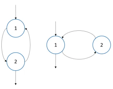
1.2 Graphic dataflow representation of a small program. . . 6
3.1 Overview of the translation and optimization process. . . 26
3.2 Normalization passes applied to the input LLVM IR in order of application. 32
3.3 Examples of do-while and while loops as natural loops. . . 33
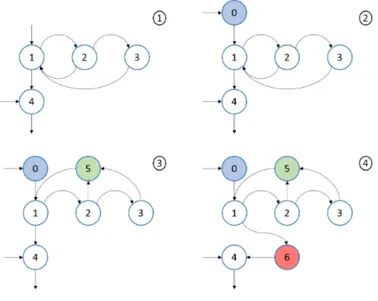
3.4 An example of natural loop normalization. In 2) we insert the pre-header, in 3) the latch and in 4) the loop exit block. . . 36
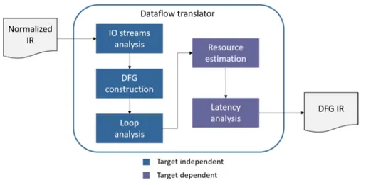
3.5 Detailed view of the dataflow translator component’s analysis and trans-formations. . . 42
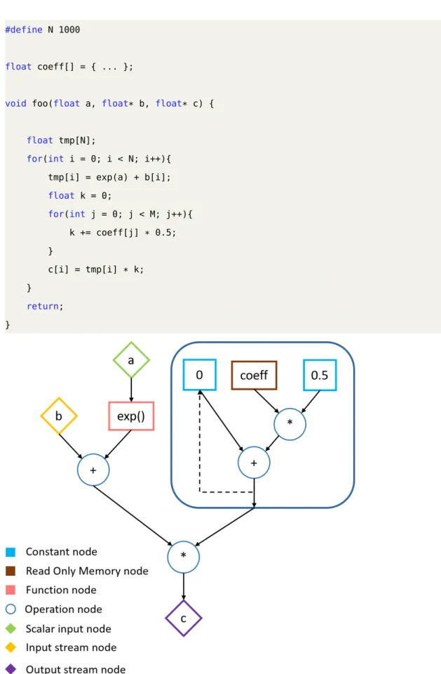
3.6 Example of a simple function and its DFG IR. . . 45
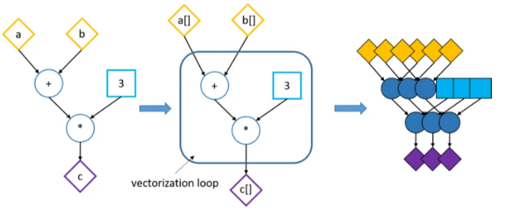
3.7 Example of a simple DFG IR subject to the vectorization optimization. . . 47
3.8 Example of fully unrolled sum over 3 elements with a functional unit with latency of 2 cycles. . . 49
3.9 Example sum over 3 elements implemented as a cyclic dataflow, with a functional unit with latency of 2 cycles. This results in a throughput of 1 sum every 6 cycles with one functional unit. . . 49
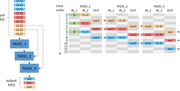
3.10 Example sum over 3 elements implemented as a cyclic dataflow with the data interleaving optimization and a functional unit with latency of 2 cycles. This results in a throughput of 1 sum every 3 cycles with one functional unit. . . 51
point adder (FADD) and exponential (EXP) operator for different hard-ware implementations on a MAX4 Galava Card. . . 57
4.1 The sequence of filters applied by the sharpen filter on the input image. The figure shows the filters and their data dependencies . . . 72 4.2 The overall structure of the Asian Option Pricing application, as
List of Tables
4.1 Summary of multiple implementations of the sharpen filter algorithm. . . 74 4.2 Summary of resource utilization for the multiple implementations of the
sharpen filter algorithm shown in table 4.1. . . 74 4.3 Summary of multiple implementations of the asian option pricing algorithm
with 30 averaging points. . . 74 4.4 Summary of multiple implementations of the Asian option pricing
al-gorithm with 780 averaging points. . . 75 4.5 Summary of resource utilization for the multiple implementations of the
Asian option pricing algorithm with 30 averaging points. . . 75 4.6 Summary of resource utilization for the multiple implementations of the
Asian option pricing algorithm with 780 averaging points. . . 76 4.7 Summary of multiple implementations of the VMC algorithm. . . 80 4.8 Summary of resource utilization for the multiple implementations of the
VMC algorithm. . . 80
Acronyms
ALM Adaptive Logic Module. VII, 1
ASIC Application Specific Integrated Circuit. VII, 4
AST Abstract Syntax Tree. VII, 20, 29
CAD Computer Aided Design. VII, 4
CFG Control Flow Graph. VII
CLB Configurable Logic Block. VII, 1
DSL Domain Specific Language. VII, 8, 9, 11, 13
DSP Digital Signal Processing. VII, 2, 4
EDA Electronic Design Automation. VII, 4
FPGA Field Programmable Gate Array. VII, XI, XIII, 1, 3, 5
GPP General Purpose Processor. VII, 3
GPU Graphics Processing Unit. VII, 3, 8
HDL Hardware Description Language. VII, 4, 5, 12, 13
HLS High Level Synthesis. VII, XI, XIII, 1, 3, 4, 5, 8, 11, 12, 13
HPC High Performance Computing. VII, 3
LUT Look-Up Table. VII, 1
RIPL Rathlin Image Processing Language. VII, 15
SCEV Scalar Evolution. VII, 32, 39, 42
Abstract
The end of Dennard scaling over the last two decades has meant that computing systems could no longer achieve exponential performance improvement through higher clock fre-quency and transistor density due to the power wall problem. Heterogeneous computing systems address this issue by incorporating specialized hardware to achieve better energy efficiency and performance. In this context, Field Programmable Gate Arrays (FPGA) have steadily grown in popularity as hardware accelerators, although the greatest obstacle to their mainstream adoption remains the high engineering cost associated with develop-ing FPGA-based applications. Despite the remarkable improvements in the effectiveness of third-generation High Level Synthesis tools, they still require some domain-specific knowledge and expertise to be used effectively. This thesis proposes a methodology and a tool that further increase the accessibility of HLS technology by providing a high level language frontend for the design of dataflow applications on FPGA. This frame-work allows software developers to write C code without focusing on FPGA-specific optimizations or concepts related to the dataflow model. The tool leverages the LLVM compiler framework to apply dataflow-specific code transformations and FPGA-related optimizations and outputs optimized code ready to be synthesized by state-of-the-art FPGA synthesis tools. A performance model tailored for dataflow computations allows obtaining accurate performance estimates before synthesis for different combinations of available optimizations. An ILP formulation of the optimization problem is then used to obtain the set of optimizations that maximizes throughput while respecting the FPGA’s resources constraints. To validate this approach, we have tested the tool on different unoptimized algorithms written in C and we have targeted MaxCompiler as a backend dataflow synthesis tool. We have compared the performance obtained by these
which ranges from 0.5x speed down to 1.34x speedup, depending on the benchmark. From the point of view of productivity, our automated optimization methodology obtains these results in about a day of work by software developers, as opposed to the several weeks of optimization by expert FPGA developers required to produce the hand-optimized designs. These results show that our methodology allows to optimize the original code and transform it into dataflow code optimized for FPGA synthesis with significantly reduced development effort.
Sommario
La fine del ridimensionamento Dennard nel corso degli ultimi vent’anni ha fatto si che i moderni microprocessori non potessano ottenere un aumento esponenziale di perfor-mance attraverso una frequenza di clock più alta e una maggiore densità di transistor. I sistemi di computazione eterogenei affrontano questo problema incorporando hardware specializzato per ottenere un miglioramento in performance ed efficienza energetica. In questo contesto, le Field Programmable Gate Arrays (FPGA) sono sempre più utilizzate come acceleratori hardware, sebbene l’ostacolo principale contro un’adozione più diffusa di questa tecnologia rimanga il proibitivo costo di sviluppo. Nonostante i notevoli miglio-ramenti dei tool di High Level Synthesis di terza generazione, questi richiedono comunque esperienza e una conoscienza specifica di dominio per poter essere utilizzati in maniera efficace. L’obbiettivo di questa tesi è proporre una metodologia ed un tool che migliorino l’accessibilità della tecnologia di HLS mettendo a disposizione un frontend per linguaggi di alto livello per il design di applicazioni dataflow su FPGA. Questo framework permette a sviluppatori software di scrivere codice in C senza doversi occupare di ottimizzazioni specifiche alle FPGA o concetti relativi al modello dataflow. Il tool sfrutta il compiler framework LLVM per applicare trasformazioni specifiche per computazioni dataflow e ottimizzazioni relative all’architettura target e produce come output codice ottimizzato, pronto per essere sintetizzato su FPGA da appositi tool commerciali. Un modello di performance specifico per computazioni dataflow permette di ottenere stime di risorse accurate prima della sintesi per diverse combinazioni di ottimizzazioni. Una formulzione ILP è utilizzata per risolvere il relativo problema di ottimizzazione per massimizzare il throughput rispettando le limitazioni in termini di risorse hardware dell’FPGA. Per va-lidare il nostro approccio, abbiamo testato il tool su diversi codici non ottimizzati scritti
taflow. Abbiamo comparato le performance ottenute dai design generati attraverso il nostro tool con design ottimizzati manualmente presenti nello stato dell’arte, ottenendo performance variabili da 0.5x a 1.34x in speedup a seconda dei benchmark considerati. In termini di produttività, la metodologia di ottimizzazione automatica proposta richiede circa un giorno di lavoro da parte di uno sviluppatore software per produrre i risulta-ti riportarisulta-ti, rispetto alle setrisulta-timane di lavoro di otrisulta-timizazzione da parte di sviluppatori per FPGA esperti richieste per produrre i design ottimizzati manualmente. Questi ri-sultati mostrano che la metodologia proposta permette di ottimizzare e trasformare il codice in ingresso in un codice dataflow ottimizzato per la sintesi su FPGA, riducendo notevolmente lo sforzo di sviluppo.
Chapter 1
Introduction
In this chapter, we introduce the context in which this work is developed as well as the definition of the problem we intend to tackle. In section 1.1 we introduce FPGAs and their main components. In section 1.2, we briefly discuss the role of FPGAs in modern computing. In section 1.3, we introduce HLS technology, in section 1.4 we introduce the dataflow computational paradigm and in section 1.5 we define what are the problems and limitations of modern HLS technology that we want to address via the proposed methodology.
1.1
FPGA overveiw
Field Programmable Gate Array (FPGA)s are reconfigurable integrated circuits inten-ded for custom hardware implementation. An FPGA is generally composed of three main building blocks: Configurable Logic Block (CLB)s, also known as Adaptive Logic Module (ALM)s on Intel FPGAs, input-output blocks and communication resources. In the interest of brevity, from this point onward we will use only the terminology relat-ive to Xilinx FPGAs, even though some architectural differences exist between different vendors. CLBs are the main components of the FPGA, used to implement either combin-ational or sequential logic. In Xilinx FPGAs, a single CLB is composed of a set of slices, the number of which can vary according to the device. Each slice is, in turn, composed of a set of Look-Up Table (LUT)s which store a combination of values that represent
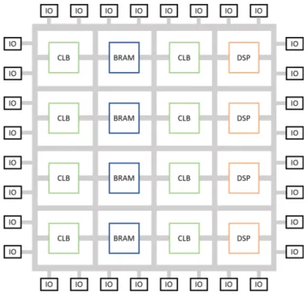
Figure 1.1: Schematic example of heterogeneous FPGA structure.
the outputs of the desired hardware function. A multiplexer reads the correct output of the function stored in a memory cell according to the given combination of input bits. Input-output blocks connect the internal logic to the I/O pins of the chip. Through their own configuration memory, IO blocks allow to configure monodirectional and bidirec-tional links as well as to set the voltage standards to which the pin must comply. The interconnection resources interconnect CLBs and IO blocks, creating a communication infrastructure that allows the realization of complex hardware circuits. In addition to these basic components, modern FPGAs contain other hardware components such as Block RAM cells (BRAM), processors, Digital Signal Processing (DSP) units and mul-tipliers. Figure 1.1 shows a schematic example of a heterogeneous FPGA and its main components.
1.2. The role of FPGA
1.2
The role of FPGA
While FPGA initially flourished in networking and telecommunications, their domain of application has expanded to include embedded system applications, due to their remark-able energy efficiency, and more recently high-performance computing [1], data centers and cloud computing [2][3][4]. Traditionally, High Performance Computing was domin-ated by General Purpose Processors, since they were inexpensive and their performance scaled with frequency in accordance with Moore’s Law. Since the mid-2000s, multicore architectures became the new way to meet the increasing demand for performance as fre-quency scaling was no longer a viable option, due to the escalation of power dissipation. Multicore architectures forced developers to adopt parallel programming models to fully exploit the computation capabilities of these systems. Given that multicore architectures already introduced notable complexity in traditional GPP programming, heterogeneous systems that couple GPPs with hardware accelerators such as GPUs and FPGAs became a viable alternative since they could provide great performance benefits, especially for very data-driven and compute-intensive applications [5]. In these scenarios, their spe-cialized hardware allows to dedicate many more transistors to meaningful calculations that in GPPs are devoted to caching and memory management hardware. Over the past decade, architectural enhancements, increased logic cell count and clock frequency have made it feasible to perform massive computations on a single FPGA chip at increased compute efficiency for a lower cost. FPGA as a service has been pioneered by Amazon with its F1 instances and is a growing trend. Microsoft introduced an interconnected and configurable compute layer composed of an FPGA chip in its cloud computing en-vironment through Project Catapult [6]. All of these factors make FPGA today one of the major players in the HPC space, as well as for embedded applications. For this reason, research surrounding FPGA development is instrumental in ensuring that this technology is used to its full potential by all types of end-users. In the next section we report a brief introduction to High Level Synthesis tools, that play a major role in the democratization of FPGAs.
1.3
High Level Synthesis technology
FPGAs were traditionally programmed through Hardware Description Languages, such as Verilog and VHDL. While these languages can be effective to program small to medium-sized, very efficient designs, the growing system complexity and the need for a shorter time-to-market for FPGA applications has created a very active field of research around CAD tools for FPGA development [7][8]. In particular, High Level Synthesis tools aim to raise the level of abstraction, allowing FPGA developers to specify their hardware design as high-level language programs. This idea of using high-level languages for hardware specification is not limited to FPGA development, as it can be used for example to design complex Application Specific Integrated Circuit (ASIC)s, but it is in FPGA development that it is most useful, since FPGA designs can be easily deployed and iteratively improved at a much lower cost compared to non-reconfigurable ASIC. HLS technology can broadly be divided into three generations, according to [7]: the first generation of tools, from the 1980s to the early 1990s, was mainly a research generation, were many foundational concepts were introduced. However, for a number of reasons these tools were a commercial failure and did not find a consistent user base. Among the reasons, [7] cites the fact that at the time RTL synthesis was just beginning to take a foothold in the community, and thus it was unlikely for behavioral synthesis to fill a design productivity gap. Moreover, these tools used little known input languages such as Silage, which represented a considerable hurdle for potential new users. Finally, the inadequate quality of results and the domain specialization of some of these tools on DSP design contributed to their limited success. The second generation, spanning from the mid-1990s to the early 2000s, saw many Electronic Design Automation (EDA) com-panies such as Synopsys, Cadence, and Mentor Graphics offering commercial HLS tools. Once again, the second generation was, overall, a commercial and user failure. At this point, designers who were used to RTL synthesis and were obtaining good and improving results, were not willing to change their design methodology unless HLS offered equally good or improved results with substantially lower effort and a gentle learning curve.
1.4. The dataflow model
Second-generation HLS tools did not offer that, and instead competed in the same space by accepting behavioral HDLs as input languages, thus keeping the user base confined to RTL-level designers. In addition, these tools generally produced low-quality results for control dominated branching logic, and overall hard to validate results with high varying time intervals. The third generation of HLS tools, developed from the early 2000s until the present day, mostly use C, C++ or SystemC as input. Unlike the first two, this generation of tools is enjoying a good amount of success. Among the reasons for this success, are the fact that many of these tools focus on specific design domains, such as dataflow or DSP, and thus are able to obtain better results, and that by accepting C-like high-level languages as opposed to behavioral HDL, they effectively broaden the user base to not only expert HDL designers. Moreover, since these tools use variations of software languages, they can take full advantage of compiler optimization techniques which con-tribute greatly to the achievement of improved design outputs. All these advancements, coupled with the rise in popularity of FPGAs, make HLS technology a central theme in computer architectures today. In particular, the proposed methodology will focus its attention on the dataflow computational paradigm, that we introduce more in detail in the next section.
1.4
The dataflow model
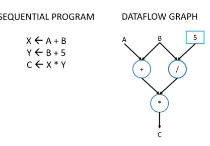
Dataflow Programming is a programming paradigm whose execution model can be rep-resented by computation nodes containing an executable block or elementary operation, having data streams as inputs and transformed data streams as output. These nodes are connected to each other forming a directed graph, which represents the entire computa-tion. An example of a dataflow graph is shown in figure 1.2. The theoretical foundation for the dataflow programming model was first introduced by Kahn [9]. In Kahn Process Networks, the nodes are sequential processes that communicate to one another via un-bounded FIFO queues. Whenever the entry FIFO queues for a node are not empty, the first values are processed and the output is sent to the FIFO belonging to the next node
Figure 1.2: Graphic dataflow representation of a small program.
in the chain. Dataflow programming has since evolved into a methodology to exploit the capabilities for parallel processing of modern computer architectures and accelerators, as well as being the basis for several visual and text-based programming languages [10]. One of the earliest examples of dataflow programming used to exploit parallel architec-tures is Streams and Iteration in a Single Assignment Language (SISAL), a text-based functional and dataflow language derived from Val. It was created in the late 80s to in-troduce parallel computation in the first multi-core machines [11]. Many other academic dataflow programming languages have been presented since [12][13][14]. An example of commercially successful dataflow visual programming language is LabView [15].
1.4.1 The dataflow atchitecture
The reason why the dataflow execution model offered an interesting alternative to the classic von Neumann execution model comes from its inherent possibility for parallelism. In the dataflow execution model, a program begins when input data is placed on special activation nodes. When input data arrives at a set of input arcs of a node called fringe, the node becomes fireable. A node is executed at an undefined time after it has become fireable. This means that, in general, instructions are scheduled for execution as soon
1.4. The dataflow model
as the input operands become available. This model is fundamentally different from the von Neumann scheme, where a global program counter dictates which instruction will be scheduled for execution in the next cycle. In the dataflow model, multiple instructions can execute simultaneously, provided that their respective inputs are ready. Moreover, since the dataflow graph of the computation already describes the data dependencies in the program, if multiple sets of data have to be computed with the same dataflow graph, the execution of the following sets of data can begin before the first has finished executing. This technique is known as dataflow pipelining.
Despite these promising features, producing hardware implementations of the pure data-flow model has been challenging [16]. One of the sources of problems is the fact that the model makes assumptions that cannot be replicated in practice, both in terms of memory and computational resources. One of these assumptions is that the arcs connecting the nodes are FIFO queues unbounded by capacity. Since having a memory unbounded by capacity is practically unfeasible, a dataflow architecture has to rely on efficient storage techniques for storing data in the FIFOs. From the point of view of computational re-sources, the dataflow model assumes that any number of instructions can be executed in parallel, as long as the respective data is available. Of course, this is not practically possible, as each instruction has to be physically executed on a set of hardware resources that are finite. In order to tackle these issues, different variations of the dataflow model have been presented in the literature. In the following sections, we report some relevant examples.
1.4.2 Static dataflow
The static dataflow architecture [17] was created to address the problem of unbounded FIFO capacity. In this version of the dataflow model, each arc can hold at most one data token. A node can fire if a token is present on each input arc and no token is present in the output arcs. This check is implemented through acknowledgment signals that travel in opposite directions to each data arc and carry an acknowledgment token. In this model, the memory for each arc of the dataflow graph can be allocated at compile time
and no complex hardware is needed to manage the FIFOs. However, the acknowledgment tokens increase the data traffic of the system by up to two times [18] and increase the time between successive firings of a node, which negatively impacts performance. This model also severely limits the possibility to exploit parallelism among loop iterations, often limiting the parallelism to simple pipelining [10].
1.4.3 Synchronous dataflow
Another relevant variation of the pure dataflow model is synchronous dataflow [19]. In this model, the number of tokens consumed and produced by each arc of a node is known at compile time. Due to these restrictions, only programs that can be expressed through dataflow nodes with no data-dependent control-flow can be represented. On the other hand, a program following this model can always be statically scheduled. Moreover, if a dataflow graph does not follow the synchronous dataflow restrictions, but contains sub-graphs which do, it may allow partial static scheduling. Especially in domains where time is an important element of the computation, such as digital signal processing, these properties are particularly relevant.
1.5
Problem definition
Despite all the advancements that third generations HLS tools have brought to the FPGA community, FPGA development is still perceived as a big hurdle, even when compared to other heterogeneous accelerators such as GPUs. Indeed, creating an optimized FPGA design from scratch, even using modern HLS technology, requires very specific domain expertise. To achieve good performance, the developer has to either guide the HLS tool through FPGA-specific and architecture-dependent optimizations or learn to program following a completely different computing paradigm through a Domain Specific Lan-guage. An example of the former is the commercial tool Vivado HLS by Xilinx [20], where the programmer needs to insert a number of pragmas to enforce specific hardware implementations of a given portion of the program logic or handle the way in which the
1.5. Problem definition
data is stored and partitioned in the different types of memories available on the FPGA. This and many other design decisions factor into the quality of the end result. To obtain a good quality design, the developer needs not only a detailed knowledge of the underlying architecture, but also of the specific HLS tool and its idiosyncratic behavior. An example where the synthesis tool requires the adoption of a completely different programming paradigm is MaxCompiler by Maxeler Technologies [21]. In this case, the programming language is a dataflow-specific DSL embedded in Java, which mixes traditional Java-style programming with custom variable classes and operator overloading to create a dataflow description of a given computational kernel, as well as an associated manager program. Once again the developer requires an advanced understanding of the tool-specific syn-tax, the dataflow computational paradigm, and the underlying architecture to produce a good design. The problem that this thesis proposes to tackle is the reduction of the gap between FPGA and software design time, by aiding the programmer with the semi-automatic optimization of C-like software functions into dataflow designs for FPGA. We have chosen the dataflow architecture as the target architectural model since it is general enough to not be limited to a single application domain while being especially proficient for data-driven and high-performance computations. Moreover, FPGAs are particularly suited for the dataflow model due to their ability to spatially distribute memory elements and functional units with customizable interconnections. Instead of trying to substitute modern FPGA synthesis tools, our framework builds on top of them, by introducing an additional frontend layer which automatically applies transformations and optimizations based on the underlying toolchain of choice, as well as the specific FPGA architecture on which the design will be synthesized. Thanks to the choice of the dataflow architectural model, we are able to evaluate the effect of the applied optimizations more precisely and therefore guide the behavior of our automated design space exploration process to deliver automatically optimized designs. A first version of this work has been published as a full paper at the 2018 IEEE International Parallel and Distributed Processing Symposium Workshops (IPDPSW) [22], and an extension of the work has been published at the 2019 IEEE International Symposium On Field-Programmable Custom Computing Machines
(FCCM) [23] as a poster. In this thesis, we extend the work with respect to both of those publications by adding an improved design space exploration model, new optimization options and a new case study.
Chapter 2
State of the art
In the state of the art, many works have been presented with the aim of providing a more accessible way to develop FPGA-based applications. This chapter is not a comprehensive review, but presents the most relevant approaches regarding FPGA development tools. In section 2.1 we review some examples of modern general-purpose HLS tools. These tools generally take as input high-level language code and output a RTL description of the circuit to synthesize on the FPGA. In section 2.2 we report examples of DSL for FPGA development in different application domains. Differently from HLS tools, these approaches use a domain-specific input language and leverage the characteristics of a particular application domain to generate an optimized RTL design. In section 2.3 we review the subset of DSL-based approaches that generate dataflow designs. In section 2.4 we review approaches based on source-to-source code transformation and optimization that rely on existing HLS or DSL-based synthesis tools as backend. Finally, in section 2.5 we discuss how the works presented relate to the proposed methodology and highlight possible shortcomings.
2.1
Modern HLS approaches
As we described in the introduction, third-generation High Level Synthesis technology has become accepted by the FPGA community as an effective method to develop FPGA-accelerated applications with less development effort and comparable results to
tradi-tional HDL design. In the next paragraph, we report some examples of relevant HLS tools in the state of the art.
2.1.1 Vivado HLS
Vivado HLS by Xilinx [20] is a commercial High Level Synthesis tool for FPGA de-velopment which supports C, C++ and SystemC as input languages. Formerly known as AutoPilot [24], it was acquired by Xilinx and has been continually supported and improved, and is today one of the most popular FPGA HLS tools on the market. It includes a complete design environment and enables users to write, test and optimize their code by iteratively applying different optimizations through the use of FPGA-specific libraries and data types. The reports available before and after synthesis allow developers to identify bottlenecks and other optimization issues in their code and select-ively optimize portions of the resulting hardware design. The tool leverages LLVM as an underlying compiler framework to extract a flexible intermediate representation and apply HLS-specific optimizations. Despite the extensive documentation, the tool is very complex and requires considerable expertise to be used effectively. Through a series of C++ libraries and optimization directives, it enables the designer to implement different computational paradigms, from master-slave to dataflow designs, with a great amount of flexibility. In addition, the designer needs to apply loop-specific optimizations, such as loop unrolling and pipelining, to extract the maximum level of parallelism from the computation, as well as choose between the different FPGA memory resources to store data. This results in a very powerful tool, which nonetheless demands a considerable development effort in order to navigate the design space and obtain a well-optimized code.
2.1.2 Bambu
Bambu [25] is an academic HLS framework that supports most C constructs. It leverages GCC to perform code optimizations such as constant propagation and loop unrolling, as well as other HLS-specific transformations. It aims at maintaining the semantics of the
2.2. DSL for FPGA-based design
original application with respect to memory access and offers a highly customizable flow through an XML configuration file which enables to control, down to which algorithms should be used, the behavior of the tool. The tool outputs a HDL description of the code which can then be synthesized through specific vendors’ synthesis tools.
2.1.3 LegUp
LegUp [26], an open-source HLS tool that aims to enable the use of software techniques in hardware design. To achieve this, the tool accepts standard C programs as input and automatically compiles them to a hybrid architecture containing an FPGA-based MIPS soft processor, as well as other custom hardware accelerators. LegUp is written in C++ and leverages the LLVM compiler framework for standard software compiler optimizations, and implements within the framework a custom backend for hardware synthesis. The HLS flow of the tool starts by running the program to be synthesized on the MIPS soft processor. This enables to profile the application and suggest an optimal hardware/software division for different portions of the program. At this point, the portion of the program to be accelerated by custom hardware goes through the actual HLS passes and is transformed in RTL, where standard commercial tools are used to synthesize the design.
2.2
DSL for FPGA-based design
Another trend that has been developing parallel to HLS technology for FPGA, is that of Domain Specific Languages. These languages are developed specifically for a given application domain, such as image processing, digital signal processing, and others. By leveraging the specificity of the target domain, they are able to produce very optimized hardware accelerators. The main downside of these approaches is that they force FPGA designers to learn new languages and specific syntax that is only applicable to a restricted domain. Moreover, DSLs make it harder to identify common problems among different domains, thus reducing the possibility of IP reuse. In the following section, we present
some relevant FPGA DSLs in the state of the art.
2.2.1 Darkroom
Darkroom is a domain-specific language and compiler for image processing applications. The architectures targeted are ASICs and FPGAs. Based on the in-line buffering tech-nique, Darkroom realizes very efficient hardware implementations of the specified pro-gram as an image processing pipeline. Darkroom specifies image processing algorithms as functional Directed Acyclic Graphs of local image operations. In order to efficiently target FPGAs and ASICs, the tool restricts image operations to static, fixed-size stencils. The programming model is similar to other image processing DSLs like Halide [27]. Images are specified as pure functions from 2-D coordinates to the values at those coordinates. Image functions are declared as lambda-like expressions on the image coordinates, the application of different image functions in succession creates the specification for the image processing pipeline to implement.
2.2.2 GraphStep
GraphStep [28] is a domain-specific compute model to implement algorithms that act on static irregular sparse graphs. The work presented in [29] defines a concrete programming language for GraphStep with a syntax based on Java. The language defines specific classes and functions to operate in the graph domain, such as node and edge classes and supports some atomic data types. Each of these classes supports different types of methods, such as "forward", "reduce tree" and "update" methods, which are expected to behave according to specific rules dictated by the GraphStep compute model. The framework has been tested on graph relaxation algorithms, CAD algorithms, semantic networks, and databases.
2.2.3 FROST
FROST is a unified backend that enables to target FPGA architectures. The input languages supported are Halide [27], Tensorflow [30], Julia [31] and Theano [32]. The
2.3. Dataflow-based design methodologies targeting FPGA
main idea behind the framework is to provide a common intermediate representation, the FROST IR, that different DSLs can be compiled to, through an appropriate frontend. The FROST IR leverages a scheduling co-language to specify FPGA specific versions of common optimizations such as loop pipelining, loop unrolling and vectorization as well as the type of communication with the off-chip memory. In this way, FROST is able to generate C/C++ code to target FPGA HLS tools such as Vivado HLS and SDAccel. Although this approach is in part related to our methodology, it presents some key differences. Firstly, the frontend languages supported are mainly DSLs or domain-specific libraries. While a common backend to target FPGAs does increase the probability that domain experts already invested in those particular languages would consider FPGA as a possible architecture, it does not address the problem of offering an easy point of access to software developers outside of those domains. Moreover, our approach shifts the emphasis from the application domain to the computational model, thus allowing a naturally broader range of applications and uses.
2.3
Dataflow-based design methodologies targeting FPGA
In this section, we report some examples in the state of the art of languages and tools which leverage the dataflow computational model to design FPGA applications. We also give a brief description of MaxJ, a dataflow DSL for FPGA which is targeted as a backend language by the methodology proposed in this thesis.
2.3.1 RIPL
Rathlin Image Processing Language (RIPL) is a high-level image processing domain-specific language for FPGA. The RIPL language employs a dataflow intermediate repres-entation based on a framework for describing rule-based dataflow actors [33]. The target backend for the RIPL IR is the CAL dataflow language [34], which is then compiled into Verilog. The RIPL IR supports different types of dataflow scheduling properties for its higher-level algorithmic skeletons. Some fall into the category of synchronous
dataflow since all the actors produce and consume the same number of image pixels at every firing, others are categorized as cyclo-static dataflow [35]. The cyclo-static data-flow paradigm still allows for static scheduling, but also allows for actors to consume and produce amounts of tokens which vary in a cyclical pattern. RIPL showcases how the dataflow paradigm is a good fit for FPGA computation since it allows independent computational resources to operate in parallel and allows to generate hardware pipelines to hide latency.
2.3.2 GraphOps
GraphOps [36] is a modular hardware library created for the fast and efficient design of graph analytics algorithms on FPGA. Despite the fact that these algorithms are tradi-tionally seen as fit for general-purpose architectures rather than hardware accelerators, GraphOps proposes an alternative model where a set of composable graph-specific build-ing blocks are linked together. Graph data are streamed to and from memory in a data-flow fashion, while computation metadata are streamed through the various GraphOps blocks as inputs and outputs. In order to enhance spatial locality when accessing ele-ments of the graph, a new graph representation optimized for coalesced memory access is also proposed. Most of the logic in the algorithms presented works well with a data-flow paradigm since feedback control is very limited. The cases where this property is violated, for example in the case of updating a global graph property for all nodes, are handled by ad-hoc control blocks.
2.3.3 Optimus
Optimus [37] is a framework designed for the implementation of streaming applications on FPGA. The input language accepted by the framework is StreamIt [38], an architecture-independent language for streaming applications. Through this language, the program-mer is able to specify a series of filters interconnected to one another to form a stream graph. Stream graphs defined in StreamIt are effectively dataflow graphs that follow the synchronous dataflow paradigm. Optimus uses a specialized filter template to implement
2.3. Dataflow-based design methodologies targeting FPGA
the filters specified in the input stream graph. A filter is generally composed of input FIFOs, output FIFOs, memories accessed by the filter, the filter itself and a controller. The filters are interconnected to one another by sharing the same FIFO queues. The framework allows for two different types of hardware orchestrations or modes of execu-tion. The first is a static scheduling mode, where the compiler dictates the number of executions of each filter. In this type of scheduling, double buffering is used between pairs of filters to provide communication-computation concurrency. The other option is a greedy scheduling, where filters execute whenever data is available and are blocked upon attempting to read an empty queue. This mode of execution allows for a trade-off between the size of the queues and overall throughput. Optimus employs a variety of FPGA-specific optimizations to optimize the overall application throughput, including queue access fusion, which makes efficient use of the FPGA SRAM characteristics, and flip-flop elimination.
2.3.4 CAPH
CAPH [39] is a dataflow DSL for describing, simulating and implementing streaming applications. It is based upon two layers or levels of abstraction. The first is an Actor Description Language (ADL), used to describe the behavior of dataflow actors as a set of transition rules involving pattern matching on input values and local variables. The second is a Network Description Language (NDL), describing the structure of the data-flow networks by applying actors, interpreted as functions, to values representing wires. Contrary to similar projects, CAPH chooses a purely functional formalism to represent dataflow actors. The CAPH compiler can be used to generate a software implementation in SystemC or produce a VHDL implementation, ready to be synthesized on an FPGA. In a recent publication [40], the authors of CAPH reflect on the reception that the lan-guage has received since its release, and speculate that one of the reasons why it couldn’t achieve widespread success was that it demanded from developers to abandon the tra-ditional imperative language paradigm and adopt a completely different programming model. Moreover, the authors mention that the possibility of implementing soft-actors
written in C/C++ would have been an attractive feature. In this respect, the meth-odology we propose aims at offering a way to implement dataflow kernels optimized for FPGA without abandoning the more common high-level programming languages and the imperative programming model.
2.3.5 MaxJ
MaxJ is a domain-specific language to design dataflow kernels for FPGA. The MaxCom-piler toolchain from Maxeler Technologies [21] allows to program several dataflow ker-nels on a DataFlow Engine (DFE), which correspond to an FPGA, following Maxeler’s Multiscale Dataflow Computing paradigm based on the synchronous dataflow model. The idea of Multiscale Dataflow Computing is to employ the dataflow model at differ-ent levels of abstraction: at a system level, multiple DFEs can be connected to form a supercomputer, at the architectural level the memory accesses are decoupled as much as possible from arithmetic operations, which are carried out with massive amounts of par-allelism using deeply pipelined structures. From an architectural standpoint, a DataFlow Engine is composed of a large number of dataflow cores, simple hardware structures that carry out only one type of arithmetic computation. The data is streamed directly from memory to these dataflow cores, where the intermediate computation results flow directly from one dataflow core to another and the results are eventually streamed back to the memory. In order to achieve high throughput, DFEs make use of what in MaxJ is called Fast Memory (FMem), which refers to the BRAM blocks present on the FPGA chip, to maintain data locality and ensure that the dataflow cores have high-speed parallel access to data. Conversely, the input and output data can be streamed directly through the PCIe or from DRAM, referred to in MaxJ as Large Memory (LMem). The Maxeler Multiscale Dataflow systems can use multiple DFEs to carry out dataflow computations through a high-speed interconnect called MaxRing. From a programming standpoint, the developer needs to provide a host code, which can be written in multiple languages like C, Python, and R, that runs on CPU and performs function calls to one or more dataflow engines. The dataflow kernel specification and its attached manager program
2.4. Source-to-source optimizers targeting FPGA
are specified in .max files, written in the MaxJ DSL. The .max files containing the data-flow kernel is a description of the computation that needs to be performed in therms of arithmetical and logical operations, whereas the manager describes the way in which the kernel is expected to interact with the host, how much data needs to be transferred and how the kernel interface relates to the host-side kernel call. MaxJ is a language embed-ded in Java, which makes use of custom classes, overloaembed-ded operators and proprietary libraries to effectively create a way to specify the structure of the underlying dataflow graph of a dataflow kernel. To be able to effectively program a Maxeler DFE the pro-grammer needs to adopt a different programming paradigm, where the statements of the program actually represent interconnections between wires and hardware resources, and constructs like for loops represent a macro for hardware replication. Despite it being embedded in a high-level language, MaxJ is more akin to a high-level hardware descrip-tion language. For this reason, MaxCompiler offers an effective way to program dataflow applications for FPGA experts, but the difficulties posed by the programming model and tools prevent it from becoming widespread in its adoption.
2.4
Source-to-source optimizers targeting FPGA
In this section, we list the main state-of-the-art works that use source-to-source code transformation and optimization strategies to target existing FPGA-based synthesis tools as a backend. These tools share similar objectives and strategies with the methodology proposed in this thesis, but differ from it in some respects and fail to meet some of the objectives outlined in the problem definition section of the introductory chapter, as will be discussed in section 2.5.
2.4.1 Hipacc
Hipacc [41] is a framework composed of a DSL and a source-to-source compiler for image processing. Originally created to target Nvidia and AMD GPUs, it has been extended to target FPGA [42]. The DSL is implemented through a C++ template and
specific classes. Operator kernels are defined in a Single Program Multiple Data (SPMD) context, similar to CUDA kernels. Custom operators are defined by inheriting the Kernel class defined by the framework and overriding the appropriate methods. DSL-specific pragmas are introduced to enable customized bit-widths, The source code is compiled into an Abstract Syntax Tree through the LLVM compiler framework, using Clang as a C++ frontend. After applying optimizations appropriate for image filters and vendor-specific transformations, the tool generates code that is later synthesized by HLS tools such as Vivado HLS.
2.4.2 FAST/LARA
A framework that aims to solve a similar problem to the ones laid out in the problem definition section of the introduction is FAST/LARA [43]. Specifically, the problems identified by the authors are the need for an intuitive, concise and well-understood lan-guage to specify dataflow designs and parametrizable optimization strategies that allow design space exploration and code reuse. The frontend language proposed is FAST, which is based on C99 syntax with the addition of some unique APIs to express dataflow computations. In order to specify the possible optimizations applicable to the code, the FAST language is coupled with LARA [44], an aspect-oriented language for embedded systems which enables to select compiler optimization strategies for specific portions of the code. The compilation backend of the framework is MaxCompiler. After the first compilation, the feedback from the backend compilation process is used to drive the suc-cessive design space exploration, until certain user-specified requirements are met. The aspect-driven optimization strategy relies on different types of aspects: system aspects, which capture system-level optimizations such as software/hardware partitioning, imple-mentation aspects, which focus on low-level optimizations such as operators optimization, and development aspects, which capture transformations that have an impact on the de-velopment process such as debugging. Using LARA the user can implement and combine these aspects to enable systematic design space exploration of all the optimization options exposed by FAST.
2.5. Unsolved issues and proposed solution
2.5
Unsolved issues and proposed solution
The main issue that prevents modern HLS technology from finding mainstream adoption among developers outside of FPGA experts, stems from the fact that these tools provide a variety of design and optimization options which are necessary for these tools to deal effectively with the complexities of hardware synthesis but force the users to develop a strong expertise and in-depth knowledge of the tool and architecture. On the other hand, DSL-based approaches reduce the complexity of the process by focusing on a particular application domain and by introducing a language that is designed to restrict the FPGA design space so that more specific optimizations become possible. The main drawbacks of these approaches are that the users need to learn how to program in very niche languages which are often limited in their use to a particular tool or application domain, and in the case of dataflow-based DSL learn to program in a completely different programming paradigm from the more common imperative languages. Our solution aims to solve these limitations by accepting standard C code as a frontend language and deals with the complexity of the design space by restricting the types of target designs to dataflow-based accelerators, which allows for an effective automatic optimization process. The tools presented in section 2.4 have some similarities to the approach proposed in this thesis but differ in some key aspects. Despite implementing source-to-source compilation to automatically optimize the code, Hipacc restricts the domain of application to image processing kernels and automatically applies optimizations specific to this domain. Our approach is more general since it applies different optimizations in order to optimize the specific dataflow function specified in terms of throughput and hardware resources used, regardless of its domain of application. Moreover, Hipacc is compiled through a DSL, which inherently restricts the usability of the tool by non-expert designers. Despite the usefulness of presenting a more familiar language as a frontend to incentivize developers to explore the possibilities offered by FPGA dataflow designs, the FAST/LARA framework introduces several complications that simply move the problem elsewhere: the LARA aspect-oriented language is possibly just as unfamiliar to the vast majority of software
developers and the need to program FPGA-specific optimizations through the use of compilation pragmas, although similar to already existing HLS approaches such as the one offered by Vivado HLS, does not diminish the amount of FPGA-specific expertise necessary to develop an optimized application. In the following chapter, we outline more in detail how the proposed methodology deals with these limitations to increase the productivity of FPGA-based design.
Chapter 3
Proposed methodology
In the following chapter, we outline the proposed methodology and describe in detail how the tool we have implemented allows a non-expert user to obtain an optimized dataflow kernel synthesizable on an FPGA starting from high-level C code. In section 3.1 we describe the overall development flow and all the major components of the framework, in section 3.2 we describe how the input code is analyzed and which transformations are applied in order to obtain a dataflow representation of the computation and section 3.3 describes the dataflow intermediate representation that is used to apply all the available optimizations. Section 3.4 describes those optimizations in detail, section 3.5 outlines the semi-automated design space exploration process and section 3.6 describes the backend code generation phase.
3.1
Proposed design flow
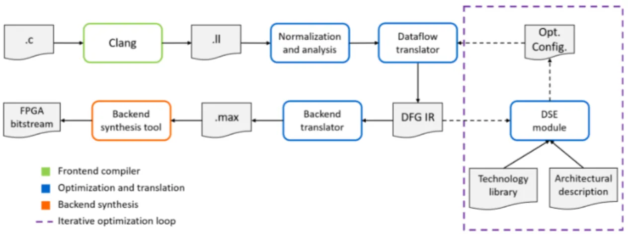
This section describes the overall design flow of the methodology proposed in this thesis and the main components of our framework. A summary of this design flow is depicted in figure 3.1. The framework we present takes as input a C source file, containing a function we want to transform into a dataflow kernel. We start from the assumption that the user has identified that part of the code as a bottleneck in a particular program, and wants to build a dataflow accelerator for that function. This assumption is reasonable, in the sense that the use of profilers such as perf [45] or valgrind [46] to identify computational
bottlenecks is not uncommon among software developers. We imagine the typical user of our framework as an expert developer who is concerned with performance improvement on a specific application and is aware of the possibility of hardware acceleration but does not possess the expertise or the resources, in terms of development time, to optimize by hand an accelerator himself.
Once the portion of the program to accelerate has been extracted into a function, the user can insert it into a simple template we provide to start the code transformation process. Internally, we obtain the LLVM IR of the function from our template by call-ing Clang [47], the C language frontend for LLVM. Alternatively, the user can directly invoke the code transformation tool from the command line on a .ll file, which is an LLVM IR module obtained through an LLVM frontend compiler, and specify the name of the function he/she wants to accelerate. Optionally, the user can decide to specify extra arguments representing a combination of available optimizations. If this is the case, the tool will produce the specified version of the kernel as a starting point for the design space exploration process. If no arguments are specified, the kernel is first trans-formed into a non-optimized version, and the later design space exploration will inform the tool on the optimal combination of optimizations to apply. The second step of the proposed methodology involves a series of code normalization steps and analysis steps, some of which are existing LLVM passes and some are custom passes implemented for our specific needs. A complete list and detailed explanation of these analyses and transform-ations is available in section 3.2. The purpose of this normalization phase is two-fold: onto one hand, we want to apply all possible transformations to the code that, while preserving semantical equivalency, make it easier for the following transformations steps to get from an imperative language like C to a dataflow representation of our function. On the other end, with some simple analysis steps, we check if any characteristics of the input code prevent it from being successfully translated into our backend language. In fact, while our tool accepts most constructs of the C language, at present it requires the code to have some characteristics, for example, no recursive function calls, to ensure a correct translation. Some of these requirements are not necessary from a theoretical
3.1. Proposed design flow
standpoint, but lifting them would require a good amount of development effort for a comparatively small gain in the expressiveness allowed in the code. From a methodolo-gical standpoint, most of these do not represent a real limitation of our approach and could be integrated into the tool at a later stage of development. After the normaliza-tion passes have been applied and the funcnormaliza-tion as been deemed fit to be translated into a dataflow kernel, the imperative code is transformed into a dataflow graph intermediate representation. This representation introduces an important element of flexibility in our methodology. At this stage of the translation process, the code has already been trans-formed from a sequence of imperative statements into a dataflow representation of the computation, where each node represents an independent computational resource, and the data flows from one node to the other to compute the expected output. Nonetheless, this representation is still agnostic to all the implementation-related and architectural constraints, therefore it can be used to target different dataflow backend languages. Once we have a first dataflow graph representation of the function, the design space explora-tion module analyzes the graph to identify the optimal combinaexplora-tion from the available optimizations that maximizes the overall throughput without exceeding the hardware re-sources available on the FPGA. All the optimizations are applied to the dataflow graph and its metadata, to obtain the final dataflow representation that will be translated into the target backend language. In this phase, we start to introduce architectural elements and hardware constraints into the optimization process which are essential to obtain a working and optimized design. To maintain as much decoupling as possible between architecture-agnostic transformations and implementation details, the domain space ex-ploration module uses a target-dependent resource estimator, that traverses the dataflow graph and estimates the amount of hardware resources required for its implementation, to infer the impact on hardware resources of code transformation that ultimately result in hardware replication, insertion of memory elements for parallel data access and increase or decrease of latency for the design. Together with target-independent transformations, the design space exploration process includes some target-dependent optimizations that leverage different possible implementations of hardware modules, the amount of
Figure 3.1: Steps of the translation and optimization process. After a first compilation step with Clang, our framework takes as input the LLVM IR source file and an initial optimization configuration and produces a dataflow intermediate representation of the design. A technological library that contains empirical data on the available hardware resources and the dataflow IR are taken as input by an optimizer that generates the optimal configuration of parameters which is used to generate the final synthesis-ready code.
ing for functional units and some degree of control over synthesis frequency. After all the optimizations have been applied, the final version of the dataflow graph is given to the backend translation module, which produces as output the optimized version of the code. To verify the results of the proposed approach, we have selected MaxCompiler [21] as a backend synthesis tool. Our framework produces two MaxJ source files containing the implementation of the dataflow kernel and its related manager. The framework also produces a test host code that is used to simulate the design and perform a basic check for semantical equivalency between the software and hardware implementations over a randomly generated set of input values within specified ranges. Once the user has veri-fied if the generated design satisfies their needs, he/she can use the backend toolchain to synthesize the design and deploy it to an FPGA device.
3.2. Code analysis and transformation
3.2
Code analysis and transformation
In this section we discuss in detail the analysis and transformation applied to the input code to get from an imperative description of the computation to a dataflow representa-tion. In the first paragraph, we discuss the assumptions that we make on the set of input functions that our framework is able to translate, some of which are necessary for the subsequent set of transformations. In the second paragraph, we discuss the analysis and normalization steps applied, how they affect the code and their utility in transitioning to the dataflow IR.
3.2.1 Underlying assumptions
In terms of overall code structure, we assume that the computation we want to accelerate can be structured as a loop over a given, generally large, amount of iterations, that can contain other arbitrarily nested loop structures, function calls, arithmetical and logical operations. While this assumption is not a trivial restriction on the type of functions that are suited for translation through the proposed methodology, it reflects the role that the proposed framework is intended to fulfill: this methodology is not intended as a general way to translate any type of computation to a dataflow architecture. There are several reasons for this choice, firstly, the problem of transforming any type of program that can be expressed in C as a dataflow kernel is too general, and the results obtained by such an effort risk being too hard to optimize, resulting in a failure similar to the one of first and second-generation HLS technology. Moreover, structuring the input code as an iteration over a large amount of data is precisely where a dataflow accelerator can obtain good results, since it is, in essence, a complex pipelined structure for processing data in a streaming fashion, and if the code can not be conceptualized in a similar way, perhaps the developer should explore different means of acceleration. All the subsequent analyses rely on this assumption since the iterations of this outer loop are interpreted as ticks for our synchronous dataflow accelerator. This does not mean that the ticks coincide with physical clock cycles on the hardware device, or that the kernel ticks and outer loop
iterations are in a 1:1 correspondence in the final translation since several factors can intervene in changing the pace at which input data is read and the latency of the different portions of the hardware pipeline. The second restriction we put on the input code is that the outer loop should not have any loop-carried dependencies, outside from reading or writing variables accessed through pointers passed as arguments to the accelerated function. This is not a restriction that has to do with the proposed methodology but is one of the current limitations of the tool. A third assumption regards the absence of recursive function calls since these are generally not well-suited for hardware acceleration. If possible, the user should modify the algorithm to perform the same computation iteratively. The fourth assumption on the input code is that all the loops present in the function with a nesting level greater than 1 have a bounded number of iterations. Lastly, we assume that the input parameters of the functions passed as pointers do not alias, both in terms of the initial memory address passed to the function, and all subsequent accesses performed through pointer arithmetic form that base address. This assumption is not unreasonable, since the use of different pointers to access the same memory location is not generally advised, and can be remedied by writing the code to abide by this rule. The reason behind this assumption is that memory accesses performed on the pointer arguments of the function through the iteration variable of the outermost loop will be interpreted as reading elements from a stream of data or writing to it, and streams are assumed to be non-overlapping and identified uniquely through the corresponding pointers in the original code.
3.2.2 Code normalization and analysis
The proposed tool operates within the LLVM compiler framework, and makes use of many analysis and transformation passes already implemented within it, as well as some custom passes. The LLVM framework provides an array of tools that allow building upon existing compiler technology and theoretical knowledge and is particularly suited for extensions and implementation of new tools due to its very modular nature. In the next paragraph, we give a brief introduction to LLVM and the LLVM IR and define some
3.2. Code analysis and transformation
concepts that will be mentioned later in the text.
Introduction to LLVM
Traditional static compilers present a modular structure composed of three main com-ponents: a frontend, an optimizer, and a backend. The frontend deals with language-specific lexical analysis and parsing, as well as statements and data structures lowering. It transforms the code in an Abstract Syntax Tree (AST), which can be converted to another intermediate representation for optimization. The optimizer is usually mostly independent from the source language and target and performs a broad variety of ana-lyses and transformations to improve the code running time and eliminate redundancy. The backend is responsible for mapping the code onto the target instruction set. In doing this, the objective is to generate not only correct code, but good code that takes advantage of the features offered by the target architecture. The main advantage of the three-phase compiler design is its flexibility: the compiler is able to support different frontends, so long as they all produce the same intermediate representation, as well as multiple backends for different architectures while maintaining the same core optimizer. Although this three-phase approach is well accepted in theory, it is very hard to fully realize. The LLVM compiler framework represents a good example of how this type of design can facilitate further developments in compiler technology, having given birth to numerous sub-projects as well as a number of independent projects that use LLVM as a starting point. In the case of this work, we relied on the LLVM C frontend compiler, Clang, to provide a reliable frontend for the C language. In terms of the optimizer, our methodology takes advantage of the features presented by the LLVM IR and some op-timization options, aiming towards compatibility with multiple frontends which support the LLVM IR as output, and presents a custom dataflow intermediate representation which builds upon the features of the LLVM IR to provide a similar starting point for dataflow-specific optimizations. This intermediate representation provides an opportun-ity to target different backend synthesis tools by simply substituting the code generation portion of our tool. The LLVM IR is a low level RISC-like virtual instruction set in three
address form. It allows linear sequences of simple instructions, like add, sub, compare and branch, as well as some high-level instructions like call and ret, which abstract away calling conventions and getelementptr, used to handle pointer arithmetic. The LLVM IR is strongly typed, with primitive types like i32 and f loat, and pointer types like i32∗. Functions and statements are also typed. The LLVM IR is Single Static Assignment (SSA)-based, allowing for more efficient optimizations. This means that in each func-tion, for each variable %f oo, only one statement exists in the form %f oo = ..., which is the static definition of %f oo. In the code snippet below we show two simple functions which add two numbers, one in a straightforward way and the other recursively, and their corresponding translation into LLVM IR.
unsigned foo(unsigned a, unsigned b) {
return a+b; }
unsigned bar(unsigned a, unsigned b) {
if (a == 0) return b;
return bar(a-1, b+1); }
define i32 @foo(i32 %a, i32 %b) { entry:
%tmp1 = add i32 %a, %b ret i32 %tmp1
}
define i32 @bar(i32 %a, i32 %b) { entry:
%tmp1 = icmp eq i32 %a, 0
br i1 %tmp1, label %done, label %recurse
recurse:
%tmp2 = sub i32 %a, 1 %tmp3 = add i32 %b, 1
3.2. Code analysis and transformation
%tmp4 = call i32 @bar(i32 %tmp2, i32 %tmp3) ret i32 %tmp4
done:
ret i32 %b }
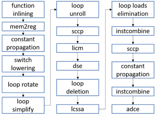
Other than being implemented as a language, the LLVM IR is also defined in three isomorphic forms: the textual format corresponding to the .ll file extension which is the one shown above, an in-memory data structure and a bytecode format, an efficient on-disk binary format corresponding to the .bc file extension. The LLVM optimizer operates on the in-memory IR representation through a series of steps called passes. A pass is a pipeline stage that operates a particular code analysis, usually producing useful metadata for subsequent passes, or some code transformation. An LLVM pass can inherit different pass interfaces depending on the granularity and type of the transformation or analysis it performs, that can operate at the module level, function level or basic block level. It also allows to specify the dependencies of the pass, in terms of transformations and analysis it requires, and its effect on the IR in terms of analysis and code properties it preserves or invalidates. These features allow writing passes in a completely modular fashion while ensuring that a given pass can clearly specify the preconditions necessary for it to perform its intended functionality. In the following paragraph, we report firstly the main analysis passes on which our tool relies, then the full list of LLVM transformation passes applied during the normalization process, describing their function and their purpose in this context. Figure 3.2 reports the sequence of passes in order of application. The version of LLVM employed is LLVM 4.0. The input for the normalization process is the LLVM IR for the function that we want to accelerate, compiled without any initial optimization.
Dominator Tree analysis
This analysis implements in LLVM the concepts of dominators and dominator tree in the CFG. These concepts are very commonly used in compilation theory, here we report the