Corso di Laurea in
Ingegneria Meccanica
A study on surface finish and electric signal of a PZT
piezoelectric ceramic machined by abrasive water jet
Supervisori: Prof. Massimiliano ANNONI Prof. Dragos AXINTE Tutor: Dr. Amir RABANI
Tesi di Laurea di: Federico ATTUATI Matricola 770008
To my family and my girlfriend for their
constant support in this long journey
i
Contents
List of Abbreviations and Symbols ... iv
Abstract ... 1
1 Introduction and State of Art ... 2
1.1 Introduction ... 2
1.2 State of art ... 3
2 Water Jet Technology ... 5
2.1 Water jet classification ... 6
2.2 The water jet system ... 8
2.2.1 The water treatment system ... 9
2.2.2 The pumping system... 10
2.2.3 The cutting head ... 11
2.2.4 The abrasive feeder ... 15
2.2.5 The catcher ... 16
2.3 The abrasive ... 16
2.4 Water jet applications ... 17
2.5 Water jet advantages ... 19
2.5.1 Advantages of water jet machining compared to laser machining ... 20
2.5.2 Advantages of water jet machining compared to EDM machining ... 21
3 Properties and Applications of Piezoelectric Ceramics ... 23
3.1 Piezoelectric materials ... 23
3.2 Theory of piezoelectricity ... 24
3.3 Polycrystalline piezoceramics ... 26
3.3.1 Lead zirconate titanate (PZT) ... 28
3.4 Piezoelectric ceramics applications ... 32
3.4.1 Piezoelectric generators ... 32
3.4.2 Piezoelectric actuators ... 32
3.4.3 Piezoelectric sensors and transducers ... 33
ii
4 Methodology ... 35
4.1 Sieving ... 35
4.2 The supporting plate ... 39
4.3 PZT sheet preparation ... 41
4.4 Signal acquisition and analysis ... 44
4.4.1 Acquisition procedure ... 44
4.4.2 Extraction of the portion of signal used in the calculations ... 45
4.4.3 Signal filtering ... 46
4.4.4 RMS calculation ... 48
4.4.5 FFT calculation ... 48
4.4.6 PSD, PSD peak and PSD peak frequency calculation .... 49
4.4.7 Graph examples ... 50
4.5 Roughness measurement ... 52
4.6 Optical microscope ... 56
4.7 Scanning electron microscope ... 56
5 Experimental Campaign ... 57
5.1 Topography of a surface obtained by abrasive water jet ... 57
5.2 Preliminary tests ... 61
5.2.1 Surface roughness analysis ... 63
5.2.2 Signal analysis ... 65
5.3 DOE experimental plan ... 70
5.3.1 Surface roughness analysis ... 72
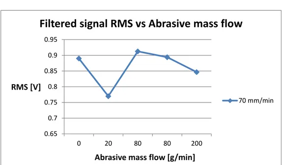
5.3.2 Filtered signal RMS analysis ... 78
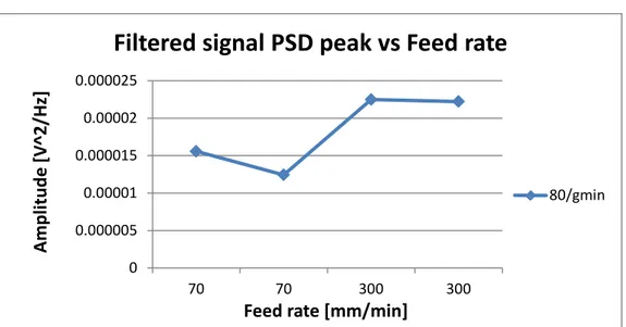
5.3.3 Filtered signal PSD peak analysis ... 79
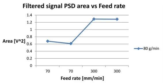
5.3.4 Filtered signal PSD area analysis ... 80
5.3.5 Filtered signal PSD peak frequency analysis ... 82
5.4 Discussion ... 84
5.4.1 Surface finish ... 84
5.4.2 Electric signal ... 85
iii
A Experimental results ... 88
A.1 List of experiments ... 88
A.2 Roughness measures ... 90
A.3 Signal data ... 92
B Statistical analysis ... 94
B.1 Surface roughness ... 94
B.2 Filtered signal RMS ... 98
B.3 Filtered signal PSD peak ... 101
B.4 Filtered signal PSD area ... 105
B.5 Filtered signal PSD peak frequency ... 108
C Matlab code used in signal analysis ... 113
D Datasheets ... 126
D.1 Water jet cutting system ... 126
D.2 Optical microscope ... 127
D.3 Profilometer ... 128
D.4 Scanning electron microscope ... 129
List of Figures ... 130
List of Tables ... 134
Bibliography ... 135
iv
List of Abbreviations
ANOVA Analysis of variance AWJ Abrasive water jet
BNC Bayonet Neill-Concelman DOE Design of experiments
EDM Electrical discharge machining FFT Fast Fourier transformation FIR Finite impulse response PSD Power spectral density PZT Lead titanate zirconate PWJ Pure water jet
RMS Root mean square
SEM Scanning electron microscope SiC Silicon carbide
v
List of Symbols
D Electric displacement 𝑑 Piezoelectric constant
E Electric field
𝐸c Coercive electric field
𝑔 Gravitational acceleration 𝐻t Hardness of target material
𝐻p Hardness of particle L Evaluation length
𝐿c Characteristic length describing the resistance of materials
𝐾c Fracture toughness
𝑝0 Water relative pressure before the orifice
𝑝1 Water relative pressure after the orifice
𝑃oil Oil pressure
𝑃water Water pressure
𝑅a Surface roughness
𝑅z Ten-point mean roughness
S Mechanical strain
𝑆oil Water pressure application section
vi 𝑆water Oil pressure application section
T Mechanical stress
𝑇c Curie point
𝑉0 Speed of water before the orifice
𝑉1 Speed of water after the orifice
𝑋RMS RMS of the vector X
𝑧0 Vertical position before the orifice
𝑧1 Vertical position after the orifice
α Significance level of the test
𝛾 Specific weight of water
𝜀T Dielectric constant under constant stress
𝜆c Cut-off length
1
Abstract
Piezoelectric ceramics can satisfy the needs of optical, electronic, mechanical and biomedical applications thanks to their properties such as electrical behaviour and electromagnetic response, high mechanical and corrosion resistance, high resistance to thermal stresses and chemical inertness. As these type of material are generally difficult to machine by conventional technologies, abrasive water jet is a promising technology compared to laser, EDM or micromachining thanks to the low forces involved in the cut, the absence of thermal stresses, high versatility and flexibility. The work will demonstrate the capability of water jet technology to successfully machine such materials, investigate the effect of process parameters on the surface finish of a thin sheet of a piezoelectric ceramic called lead zirconate titanate (PZT) and analyze the electric signal directly acquired from the workpiece during the cut in order to have a deeper understanding of the cutting process and jet-piece interaction.
Keywords: Piezoelectric, ceramic, PZT, abrasive water jet, roughness, electric
signal.
Sommario
Le ceramiche piezoelettriche possono soddisfare i bisogni di molteplici applicazioni in numerosi campi, come ad esempio quello ottico, elettronico, meccanico e biomedico, grazie all’accoppiamento elettromeccanico dovuto all’effetto piezoelettrico e alle loro proprietà quali l’alta resistenza meccanica, alla corrosione, agli stress termici e l’inerzia chimica. Generalmente questo tipo di materiali è difficile da lavorare con tecnologie convenzionali e innovative come il laser, l’EDM o le microlavorazioni. La tecnologia water jet, al contrario, risulta promettente poiché presenta basse sollecitazioni meccaniche e termiche unitamente ad un’alta flessibilità e versatilità. Questo lavoro dimostrerà la capacità della tecnologia water jet di lavorare con successo una ceramica piezoelettrica chiamata zirconato titanato di piombo (PZT). Verrà investigata la finitura superficiale del taglio e analizzato il segnale elettrico acquisito direttamente dal pezzo in lavorazione nel tentativo di aumentare le conoscenze sul processo di taglio e sull’interazione getto-materiale.
Parole chiave: Piezoelettricità, ceramica, PZT, abrasive water jet, rugosità,
2
Chapter 1
Introduction and State of Art
1.1 Introduction
Piezoelectric ceramics are nowadays widely used thanks to their capability to transform an electrical field into a mechanical displacement and vice versa in addition to the high hardness, the wear resistance, the thermal resistance and the chemical inertness typical of a ceramic material. Their peculiar property makes them particularly suitable for a number of applications, for example sensors, actuators, transducers or generators. However, conventional machining methods such as grinding, turning or diamond wheel machining are expensive. In fact, the brittle behavior of the material makes it hard to obtain a high dimensional precision, while the high hardness causes a severe tool wear. Moreover, the shapes of the features cannot be too complex because of the limitation imposed by the tool geometry. Electrical discharge machining can achieve strict geometrical tolerances and can machine complex geometries but can be used only with conductive materials. Thermal damage can occur with laser machining, thus deteriorating the performance of the final product. On the other hand, water jet is an appealing technology thanks to the low mechanical and thermal stress during the cut and the absence of chemical alterations.
The aim of this work is to demonstrate that a hard-to-cut material as a piezoelectric ceramic can be successfully machined with a water jet, to investigate the surface finish of the kerf and to analyze the electrical signal collected from the workpiece during the cut since useful information regarding the cutting process can be obtained from it. To have a better insight into the microstructural aspects and to better understand the interaction between the material and the water jet, a SEM analysis has been performed.
The first chapters will introduce the water jet technology and explain the characteristic of the ceramic material employed in the work. The following chapters will give a detailed description of the experimental work and of the used procedure. Lastly, conclusions and possible future developments will be presented.
3
1.2 State of art
Abrasive water jet technology is relatively young and various aspects, like the jet structure or the material – jet interaction, are still being investigated. The erosion mechanisms of ductile material are known thanks to the works of Finnie [1][2] and Hashish [3][4][5]. However, brittle materials exhibit a more complex behavior still not completely assessed. A few models for abrasive water jet machining of brittle materials have been proposed. They are based on the indentation fracture mechanics, as the damage pattern observed in the experiments is similar to the one observed in the quasi-static indentation tests with diamond indenters. The material removal is based on formation and propagation of cracks. The impact zone is surrounded by median-radial cracks and presents an irreversible deformation. During the unload phase, if the load exceeds a threshold value, lateral cracks are developed thus leading to chipping and, consequently, to erosion [6].
Despite the fact that ceramics are brittle materials, it is believed that plastic deformation takes part in the erosion mechanism [7]. In [8] the researchers found proofs of ductile erosion if the kinetic energy is below a threshold value. This idea is confirmed in [9][10]. The authors present evidences of development of high local temperatures due to abrasive high energy and low thermal conductivity of ceramics. The presence of such high temperatures leads to chemical reactions (e.g. oxidation) and softening of the material, which can consequently show a plastic behavior.
There exist some predictive models for brittle materials which consider plastic deformation mechanism: two elastic-plastic models are presented in [11] for predicting the depth of cut. Both models include fracture toughness 𝐾c into the formulation and one of them starts from the assumption that plastic deformation is relevant in material removal mechanisms. Zeng and Kim [12] present a model for the prediction of material removal rate for brittle materials. They consider the total eroded volume to be the sum of volume eroded by plastic flow, which is predicted using Finnie’s model, and volume eroded by brittle fracture.
However, models start from the assumption that abrasive particles are infinitely hard and rigid. [13][14][15] demonstrate that this is a correct assumption when the ratio between material hardness 𝐻t (target hardness) and abrasive hardness Hp (particle hardness) is << 1. An indention-induced fracture mechanism is
observed in this case and the machined surface shows an high wear. When the ratio tends to the unity, the value of material removal rate considerably drops, the microchipping erosion mechanism becomes dominant and the surface is smoother. Models based on infinitely hard abrasive are not valid in this situation anymore.
Abrasive energy is another important factor that must be taken into account when discussing cutting mechanisms. [9][10][16] show the presence of two
4 different removal mechanisms in brittle materials according to the energy density. In fact, two different wear zones are observable. In the upper side of the kerf, where abrasive still has a high amount of energy, transgranular fractures and microcutting occur. Moreover, the grains and the binder are equally eroded. Conversely, intergranular cracking dominates the lower part of the surface and the erosion occurs on the softer binder, while the grains fall apart as the matrix is eroded. Non-linear fracture phenomena such as crack arrest and crack branching have been observed in [16]. [17] suggests to use a characteristic length 𝐿c to describe the resistance of strain-softening materials to a jet impact. The surface roughness is not usually the main topic in water jet papers, and few works can be found specifically on it. Hocheng and Chang [18] affirm that, when machining Al2O3 and Si3N4 ceramics, the roughness increases with the feed rate, while an increase in abrasive mass flow helps to improve the surface finish. Pressure provides the energy to cut thicker materials, but has no relevant effect on the roughness. In [19] roughness is modeled using artificial neural network and regression analysis method. In [1] an investigation on the finish of metals is carried out. The decrease in feed rate improves the surface finish, which, on the other hand, gets worse with the increase in thickness. [20] presents an optimization of the cutting parameters to obtain the best kerf quality of a thin sheet of a piezoelectric ceramic.
Despite the efforts and the knowledge already acquired on the water jet technology, more studies are required for a deeper understanding and a better control of the water jet machining process of ceramic materials. This work will contribute to the study of surface finish of ceramics machined by abrasive water jet and to the study of the interaction between the jet and the material.
5
Chapter 2
Water Jet Technology
Water jet (WJ) is a non-conventional technology with its strength lying in simplicity and flexibility in addition to some peculiarity of the process which will be explained later in this chapter.
Simplicity can be found in the operating principle: water is pressurized up to 600 MPa in a hydraulic circuit by a pump, then is let flow through a small hole named orifice which converts water pressure into speed. In this way, water can reach speeds higher than 800 m/s. Flexibility comes from the ability of water jet technology of machining virtually every material and cutting shapes both in 2D and 3D; the maximum piece thickness that can be cut depends only on the maximum water pressure provided by the pump. Water has been chosen for carrying energy because it is characterized by large availability, low costs and no environmental issues.
First experiments date to 1950’s, when Norman Franz, a forestry engineer, started experimenting which high pressure water to cut trees into lumber. His experiments did not lead to a successful commercial cutting machine but they prove that water under high pressure and high velocity could cut materials. However, the technology did not advance considerably until 1970’s, when Mohamed Hashish had the idea of introducing abrasive into the jet; this represented the turning point of water jet technology, allowing the WJ technology to expand its application field. Since then, many types of water jet have been developed, including abrasive water jets, cavitation jets, ice water jets, hybrid jets [21]. The possibility to easily cut a wide variety of materials and shapes, the low forces transmitted to the workpiece, the absence of heat affected zone and the environmental sustainability make WJ a particularly suitable and competitive technology for modern unconventional machining.
6
2.1 Water jet classification
As stated before, various types of jets have been developed to satisfy the needs of particular applications. However, the most common classification of water jets focuses on the presence of abrasive into the flow, resulting in a division into two groups: pure water jets (PWJ) and abrasive water jets (AWJ)
Pure water jet relies only on the cutting power of the water stream. Orifice with small diameters, usually between 0.05 and 0.15 mm, focalizes the jet in order to have a small impinging area and an high density of energy. PWJ is suitable for cutting softer materials such as food, paper, wood, fabric and leather. PWJ problems are related to the failure or the clogging of the orifice, but a proper purification of the water can extend the life and the efficiency of this component.
Figure 2.1: Pure water jet cutting head [22]
Harder materials such as ceramics, metals and glass cannot be machined using a pure water jet. Abrasive water jet technology has been developed to compensate the lack of cutting power of a pure water jet. A sand, usually garnet, is added to the stream in a component called mixing chamber, usually placed below the orifice, where the flowing water creates a suction effect which makes the abrasive enter the jet. After that, a focusing nozzle makes the jet coherent.
On the contrary of what happens in pure water jetting, water is now used to accelerate and direct the abrasive against the workpiece rather than a tool for machining the workpiece. In fact, the actual cutting is performed by the abrasive, which has a hardness equal or greater than the hardness of the target material.
7
Figure 2.2: Abrasive water jet cutting head [22]
To drag abrasive more efficiently, water flow is increased by means of bigger diameters compared to the ones of a pure water jet machine. The orifice diameter is usually 0.3 mm and the focuser is three times bigger, having a diameter of 1.02 mm. The length of the focusing nozzle is usually 76 mm.
An abrasive water jet machine is more expensive in respect to a pure water jet machine. The higher costs are caused by a more complex set up (a feeder for the abrasive, the mixing chamber), by the abrasive itself and by the wear of the focusing tube caused by the fact that the AWJ machine erodes itself; the nozzle has a cost of 80-100 € and last for 80-100 hours when the abrasive used is garnet and less if the abrasive is harder as alumina or silicon carbide. The substitution of the focuser, together with abrasive, is a large part of operative costs.
Another issue of AWJ machining is the formation of agglomerates of abrasive in the focuser which lead to an arrest of the process. However, with new and improved designs of the mixing chamber, this occurrence is becoming less and less present.
In conclusion, abrasive water jetting is a more powerful but also more delicate and costly technology compared to pure water jetting. For soft materials, the better choice is PWJ due to the lower costs involved, whereas the AWJ is the only solution for machining metals and ceramics.
8
Figure 2.3: Water jet cutting heads [22]
2.2 The water jet system
This section will explain in detail the composition of a water jet machine. A water jet system is composed by [23]:
- Water treatment system - Low-pressure circuit (oil) - Pumping system
- High-pressure circuit (water) - Cutting head
- Abrasive feeder (only abrasive water jet) - Catcher
9
Figure 2.4: Abrasive water jet plant [24] 2.2.1 The water treatment system
The water treatment system is needed for filtering the water coming from the water network and is designed specifically for the characteristic of the water supply. It usually consists of micrometrics filters, carbon filters and an inverse osmosis apparatus intended to eliminate solid particles and some chemical elements like calcium, magnesium, chlorides and sulfides known to be detrimental to the water jet system. In fact, solid particles accelerate the wear of pumping system, pipes, valves, orifice and focuser, while calcium and
10 magnesium are known to form deposits which cause inefficiencies leading to pressure drops. Lastly, chlorides and sulfides lead to corrosion of metallic parts. The water treatment system is thus necessary for granting the correct functioning of a water jet machine.
2.2.2 The pumping system
The pumping system is the heart of a water jet machine. Its task is to raise water pressure to the value used in the process, usually between 200 and 600 MPa. It is composed by a pressure intensifier, a water accumulator, an oil accumulator and an hydraulic pump. In the pumping system, the pressure in the oil circuit is increased and transmitted to the water circuit thanks to the equilibrium of forces principle. The hydraulic pump is used to compress the oil, while the intensifier is the part in contact both with water and oil in which the transformation occurs. The equation describing the phenomenon, graphically represented in Figure 2.5, is the following:
𝑃water· 𝑆water = 𝑃oil· 𝑆oil (2.1)
𝑃water = 𝑃oil·𝑆water𝑆oil (2.2)
Figure 2.5: Equilibrium of forces principle applied to the intensifier [23]
The oil chamber is at low pressures but the area of application of the pressure is big, while the water side has a smaller section, therefore allowing the water to reach high pressures. Common values for the intensification ratio (the ratio
𝑃water
𝑃oil ) are between 10 and 40.
There are two types of intensifiers: single-acting and double-acting (Figure 2.6). Single-acting intensifiers can pressurize the water only in the compression stroke and, in order to obtain an adequate water flow and reduce water pressure fluctuations, there should be at least two of them in the machine. To increase the
11 maximum water flow and reduce even more the pressure fluctuations, three or more intensifiers can be used; however, attention must be paid to their phasing. Double effect intensifiers, instead, pressurize water in each stroke direction.
Figure 2.6: Single-acting intensifier (left) and double-acting intensifier (right)
In a pumping system there are two accumulators, one for the water circuit and one for the oil circuit, damping the fluctuations in pressure and accumulating energy and fluid. The presence of a water accumulator directly influences cutting quality. In fact, at high pressures like those used in a water jet machine, water is compressible and the supply of water coming from the intensifier is discontinuous (the first part of the piston stroke compress the water instead of inject it in the high-pressure circuit). The oil circuit, too, presents pressure fluctuations which, despite being damped by the oil accumulator, are reflected in the intensifier moving less fluidly, thus causing water pressure fluctuations. All those effects sum up and lead to a discontinuous cutting action which is clearly detrimental for the quality of the cut, making necessary the presence of a water accumulator.
2.2.3 The cutting head
The cutting head is the part of the machine in which the transformation of pressure energy into kinetic energy, the jet focusing and the mixing of water and abrasive in case of abrasive water jet occur. Each part composing the head (orifice, mixing chamber and focuser tube) must be coaxial in order to obtain the best possible result in terms of jet shape and, thus, cutting quality.
12
The orifice jewel
The orifice jewel, or simply orifice, is the part that converts the pressure energy of water into kinetic energy. It is made by synthetic or natural diamond, ruby or sapphire due to their high resistance to heat, wear, corrosion and pressure.
Figure 2.7 shows a ruby orifice.
Figure 2.7: A ruby orifice [25]
It is possible to explain how the energy transformation works thanks to Bernoulli’s principle (Equations 2.3 and 2.4). In the following discussion, the hypothesis of perfect fluid, meaning that the fluid is incompressible and with a coefficient of viscosity equal to zero, and the hypothesis of no losses of energy during the transformation are considered. It can be said:
𝑝0 𝛾
+
𝑉02 2𝑔+ 𝑧
0=
𝑝1 𝛾+
𝑉12 2𝑔+ 𝑧
1 (2.3) (𝑝0− 𝑝1) 𝛾+
(𝑉02− 𝑉12) 2𝑔+ (𝑧
0− 𝑧
1) = 0
(2.4) The subscript 0 identifies the section before the orifice, the subscript 1 the section after the orifice, 𝑔 is the gravitational acceleration, 𝛾 is the specific weight of water, p is the relative pressure, meaning that the contribute of atmospheric pressure has been subtracted, and for this reason 𝑝1, which is the pressure of the water after the orifice, is equal to zero as it is the atmospheric pressure. 𝑧0− 𝑧1 is a value close to 0 and much smaller compared to the other two terms, thus it can be neglected. 𝑉0 is the speed of the water before the orifice, usually 2-3 𝑚13 comparison with 𝑉1 (the speed of the water after the orifice) which is usually above 800 𝑚
𝑠.
After these simplifications and solving for 𝑉1, the equation is:
𝑉
1= �
2 𝑝0𝜌 (2.5) where 𝜌 is the density of water.
However, water compressibility must be taken into account because the high pressures involved in the process. The model which considers water compressibility is shown in Equation 2.6, and the speed of the water after the orifice is calculated in Equation 2.7 [26]:
𝜌 𝜌0
= �1 +
𝑃 𝐿�
𝐶 (2.6)𝑉
1= �
𝜌 2 𝐿 0(1−𝐶)��1 +
𝑃 𝐿�
1−𝐶− 1�
(2.7) where C = 0,1368 and L = 300 MPa are two constants.Equation 2.7 shows the value of the theoretical speed of the water out of the
orifice when no energy losses occur and water is considered compressible.
The mixing chamber
In case of injection abrasive water jets, grit and water are merged in the cutting head inside the mixing chamber. The abrasive flows from the hopper, a container attached to the cutting head which stores the sand, to the cutting head through a plastic tube. There are various solutions proposed by cutting heads producers in attempt to make the mixing process as uniform as possible in order to achieve a higher cutting quality. So, abrasive can enter mixing chamber from one up to four different holes, usually placed at equal distances one from the other, and the conveying tubes can be perpendicular or slightly tilted. Figure 2.8 shows the different shapes of the mixing chambers:
14
Figure 2.8: Commercial mixing chambers produced by a) Accustream, b)
Accustream, c) PTV
The abrasive grit enters the mixing chamber thanks to gravity and Venturi effect. Venturi effect is the reduction in pressure generated by a high speed fluid; in this case, the high speed water jet create a depression inside the mixing chamber, easing the flow of the abrasive from the hopper to the mixing chamber. Inside the mixing chamber, a depression caused by the high speed jet which creates a suction effect helping the flow of abrasive.
Water starts to transfer momentum to abrasive particles as they are absorbed into the jet before reaching the last part of the cutting head: the focusing tube.
The focusing tube
The last part of the machine right before the workpiece is the focusing tube (Figure 2.9). In it, the jet is made coherent and with the desired diameter, while water completes the transferring of momentum to the abrasive.
The top of the focusing tube presents a conical entrance to help the channeling of the jet.
15 The focuser is subject to severe wear due to erosion and abrasion caused by abrasive particles as shown in Figure 2.10. Erosion occurs at the beginning of the tube, where impingement angles are high. Toward the end of the focuser, where the jet is almost aligned with the axis of the focuser and impact angle tends to zero, the material removal is caused by abrasion.
Figure 2.10: The wear process of a focuser
In order to resist to such a high wear, focusers are usually made by materials with high hardness as sintered tungsten and boron carbides.
2.2.4 The abrasive feeder
Attached to the moving part of the machine above the cutting head there is the abrasive feeder, also called hopper, which is a container filled with the sand used during the cut. A plastic tube goes from the feeder to the mixing chamber allowing the flow of abrasive from the hopper to the cutting head. The abrasive flow can be regulated rotating a marked indicator.
16
2.2.5 The catcher
Right below the workpiece, there is a big water tank called catcher with the functions of collecting the jet, dissipating its remaining energy (usually around 75% of the starting energy), damping the noise caused by the machine, avoiding dangerous jet back-reflections which can damage the machine or hurt people and collect scraps and abrasive particles for recycling or disposal.
A metal grid is usually placed above the catcher in order to support the workpiece.
2.3 The abrasive
In AWJ, abrasive sand is added to the jet. Abrasive should not be hygroscopic and should have a low dust content for safety matters and for avoiding clogging in the mixing chambers. The abrasive is sold in bags and the average dimension of the grit is indicated using the mesh size, commonly #80 or #120, which correspond to an average particle diameter of 180 and 125 microns. Thanks to its low cost and good cutting performance, garnet is the most used abrasive. Harder and sharper abrasives such as alumina or silicon carbide can be used when an higher cutting power is needed, allowing the machining of thicker or harder materials. However, the better cutting performances are also reflected in a faster wear of the focuser. Figure 2.12 shows some of the most common abrasives employed in abrasive water jetting.
17
2.4 Water jet applications
The great flexibility, scalability and the peculiar characteristic of water jet technology makes it suitable for a great number of applications [27].
Cutting of 2D and 3D shapes
The main application of water jet. A pure water jet is capable of cutting leather, food, wood and other soft materials; abrasive water jet is needed for harder materials such as metals, ceramics and stones. Composite materials can be easily cut with WJ because the different properties of the matrix and the fibers do not affect the process. The maximum thickness which can be cut depends only on the maximum pressure provided by the pump, but it is generally around 300 mm.
Water jet is commonly used for cutting 2D shapes out of a plate, but thanks to 5-axis machines it is also possible to cut 3D shapes. The complexity of the shape is limited by the jet diameter. For this reason, micro abrasive water jet technology has been developed. It is capable of machining features in the range of 200 – 300 µm [28].
Figure 2.13: A 3D shape cut with WJ technology [29] Drilling
It is possible to make holes as small as the jet diameter and, thanks to 5-axis machines, holes can have an angle different from 90 degrees.
Turning and milling
These two applications, in particular turning, are still in a development phase but tests showed water jet capability of turning axis-symmetric parts (for example grinding wheels [30]) and milling surfaces. In WJ turning (Figure
18 radially to produce the required turned surface. This technique may facilitate production of rotational-symmetries in hard to cut materials.
Figure 2.14: Water jet turning
WJ milling works in control of depth, meaning that process parameters are chosen in order to keep the depth of penetration to a fixed value. A mask made by a material harder than the target one can be used to obtain better results when cutting thin walls or corners [31]
Figure 2.15: A shape obtained by water jet milling [32] Forming
19
Dismantling and decommissioning
Thanks to the low temperatures during the cut and the capability of machining big parts, water jet can be used for the decommissioning of nuclear facilities [34] and dismantlement of weapons
Surface treatments
Water jet can be used in processes that modify the surface like cleaning [35], rust removal, peening [36], stripping, polishing [8] or texturing.
2.5 Water jet Advantages
The Water jet machining rise in popularity is completely justified by a series of advantages which, together with simplicity and flexibility, make this technology suitable for a wide range of applications. The general advantages of WJ machining are listed below [22]:
• Cutting virtually any materials: the target material does not need to have specific properties in order to be machined. The only property of interest is its hardness when choosing between PWJ and AWJ.
• Machining thick materials: despite the majority of parts are less than 25 mm thick, WJ is capable of cutting through thickness up to 300 mm of steel.
• Cold cut: the little heat WJ machining generates (the maximum workpiece temperature is around 50 °C during piercing) is removed by water, thus avoiding the formation of a heat affected zone (HAZ) which would cause alterations in chemical and physical properties of the material. For this reason, it is possible to machine parts that have already been heat treated.
• Low cutting force: WJ cutting forces are really low (some newtons). This results in no residual stresses. Moreover, brittle materials and thin features like walls 0.25 mm thick can be easily machined.
• Almost burr free: by correctly setting up the process it is possible to avoid the formation of burrs which would require further machining operations.
20 • No extra coolant needed: it is not necessary to buy any coolant since the
water needed for cutting also removes heat from the cutting area.
• Simple fixturing: forces developed by WJ machining are mostly vertical, with small forces in the horizontal direction. For this reason, the fixturing generally consists in fixing the workpiece to the metal grid above the catcher with clamps or weights.
• A few material removed: WJ cuts are around 1 mm wide resulting in a limited production of scraps, meaning it is possible to save money since less material is needed. Moreover, if the material is hazardous, the costs related to the disposal will be less compared to the costs of other machining technologies.
• Environmentally friendly: as long as the machined material is not hazardous, the spent abrasive and waste material become suitable for landfill. The most commonly used abrasive, garnet, is an inert mineral and can be disposed of with other trash. Excess water is simply drained to the sewer. When hazardous materials are machined, water must be recycled and scraps must be disposed of appropriately. However, very little metal is actually removed in the cutting process, keeping the environmental impact relatively low.
Probably, the biggest environmental impact of WJ machining is caused by the pumps as they require a considerable amount of electricity.
To fully understand the potentiality of WJ machining, it is necessary to compare it to its direct competitors: laser machining and electrical discharge machining (EDM).
2.5.1 Advantages of water jet machining compared to laser machining
Nowadays, laser technology is the best choice for a fast and precise cutting of materials compatible with the laser radiation when the parts are thin and high volumes of production are involved. Anyway, WJ technology presents some advantages compared to laser technology [22]:
• Machining a wider range of materials: WJ can machine reflective materials such as copper and aluminum and heat-sensitive materials which laser machining cannot cut.
21 • No heat affected zone: WJ does not heat the workpieces and does not
change their properties. There are also no thermal distortions, which can occur with certain types of laser.
• Thicker parts: laser can cut through a limited thickness, usually around 5 mm. WJ can cut successfully parts up to 300 mm thick by lowering feed speed and increasing pressure.
• Homogeneity of material is not important: multilayer and composite material cannot be machined using a laser beam because of the different response to laser radiation of each material. WJ is not affected by a change in composition.
• Planarity is not fundamental: in laser application, the material has to be as uniform as possible since a change in surface planarity leads to a loss of focus and therefore cutting power. On the other hand, such changes have negligible effect on the efficiency of a WJ cut.
• No burrs and better edge finish: most types of the laser cutting causes the melting of the material which is difficult to remove completely, resulting in burrs on the lower side of the kerf and a rougher, scaly edge. WJ, due to the abrasive nature of the process, does not have burrs and have a fine, sand-blasted surface.
• Lower capital equipment and maintenance costs: it is possible to buy some water jet centers for the same price of a laser machine. Moreover, maintenance is easier and cheaper on a water jet machine.
2.5.2 Advantages of water jet machining compared to EDM machining
In EDM, a series of electric arcs rapidly discharge between an electrode and the workpiece, causing the melting and vaporization of the material. A continuous flow of non-conductive coolant such as kerosene or deionized water flushes away the removed particles. While the process is extremely slow, it can create complex features that are hard to machine with other technologies and satisfy strict tolerances.
A list of advantages of WJ on EDM is presented below: • Faster: WJ machining is faster than EDM.
22 • Machining a wider range of materials: EDM requires the target material
to be electrically conductive. WJ does not have this limitation.
• Bigger parts: the only dimensional limit of parts made using WJ is the size of the x-y table. It is uncommon to machine big parts with EDM due to its low removal rate.
• Less set up: in general, EDM set up requires more attention, while in WJ the fixturing consists in weighing down the material without the need of being elaborate or precise.
• Makes its own piece hole: in some types of EDM, such as wire-EDM, a hole must be created by a different process. Water jet can pierce the material on its own, requiring no additional machining.
23
Chapter 3
Properties and Applications of Piezoelectric
Ceramics
Advanced ceramics are widely used thanks to their high hardness, wear resistance, thermal resistance and chemical inertness. The following chapter will introduce the piezoelectric effect, will give an overview of piezoceramics and will describe PZT, the material used in the experimentation. The material removal mechanisms of ceramics will be also discussed.
3.1 Piezoelectric materials
In 1880 Jacques and Pierre Curie discovered the piezoelectric effect which links the electrical and mechanical behavior in piezoelectric materials. The electric charge displacement caused by a mechanical stress is called direct piezoelectric effect [37]. Vice versa, the arise of mechanical stress in a material in response to an electrical voltage is the converse piezoelectric effect [37]. The effect is caused by an asymmetry in the distribution of the electrical charge in the crystal that generates an electric dipole moment when a strain is applied. Figure 3.1 shows the two piezoelectric effects.
24 Some naturally piezoelectric materials such as quartz, tourmaline or Rochelle salt can be found but nowadays most of the materials employed are made artificially as, for example, piezoeceramic (e.g. PZT), piezocomposites and piezopolymers (e.g. polyvinylidene fluoride also called PVDF).
3.2 Theory of piezoelectricity
Monographs like [37] discuss the various mathematical aspects of the theory of piezoelectricity. The simplest formulation of the theory of piezoelectricity is the linear theory which applies when small electrical and mechanical amplitudes are involved. In this condition, the relationships between the mechanical strain or stress components and the electric field or the dielectric displacement components are linear and the relations are coupled. The relations describing the coupling between mechanical stress T, mechanical strain S, electric field E and electric displacement D are the following:
𝑆𝑝 = 𝑠𝑝𝑞𝐸 𝑇𝑞+ 𝑑𝑝𝑘𝐸𝑘 (3.1)
𝐷𝑖 = 𝑑𝑖𝑞𝑇𝑞+ 𝜀𝑖𝑘𝑇 𝐸𝑘 (3.2)
where 𝑠𝑝𝑞𝐸 is the elastic compliance constant at constant electric field, 𝜀𝑖𝑘𝑇 is the dielectric constant under constant stress, 𝑑𝑝𝑘 is the piezoelectric constant, 𝑆𝑝 is the mechanical strain in p direction, 𝐷𝑖 is the electric displacement in i direction, 𝑇𝑞 is the mechanical stress in q direction and 𝐸𝑘 is the electric field in k
direction. The matrix form of Eq. 3.1 and Eq. 3.2 is the following [39]:
⎣ ⎢ ⎢ ⎢ ⎢ ⎡𝑆𝑆1 2 𝑆3 𝑆4 𝑆5 𝑆6⎦ ⎥ ⎥ ⎥ ⎥ ⎤ = ⎣ ⎢ ⎢ ⎢ ⎢ ⎢ ⎡𝑠11𝐸 𝑠12𝐸 𝑠13𝐸 𝑠14𝐸 𝑠15𝐸 𝑠16𝐸 𝑠21𝐸 𝑠22𝐸 𝑠23𝐸 𝑠24𝐸 𝑠25𝐸 𝑠26𝐸 𝑠31𝐸 𝑠32𝐸 𝑠33𝐸 𝑠34𝐸 𝑠35𝐸 𝑠36𝐸 𝑠41𝐸 𝑠42𝐸 𝑠43𝐸 𝑠44𝐸 𝑠45𝐸 𝑠46𝐸 𝑠51𝐸 𝑠52𝐸 𝑠53𝐸 𝑠54𝐸 𝑠55𝐸 𝑠56𝐸 𝑠61𝐸 𝑠62𝐸 𝑠63𝐸 𝑠64𝐸 𝑠65𝐸 𝑠66𝐸 ⎦ ⎥ ⎥ ⎥ ⎥ ⎥ ⎤ ⎣ ⎢ ⎢ ⎢ ⎢ ⎡𝑇𝑇12 𝑇3 𝑇4 𝑇5 𝑇6⎦ ⎥ ⎥ ⎥ ⎥ ⎤ + ⎣ ⎢ ⎢ ⎢ ⎢ ⎡𝑑𝑑11 𝑑12 𝑑13 21 𝑑22 𝑑23 𝑑31 𝑑32 𝑑33 𝑑41 𝑑42 𝑑43 𝑑51 𝑑52 𝑑53 𝑑61 𝑑62 𝑑63⎦ ⎥ ⎥ ⎥ ⎥ ⎤ �𝐸𝐸12 𝐸3 � (3.3) �𝐷𝐷12 𝐷3 � = �𝑑𝑑2111 𝑑 𝑑1222 𝑑 𝑑1323 𝑑 𝑑2414 𝑑 𝑑1525 𝑑 𝑑1626 𝑑31 𝑑32 𝑑33 𝑑34 𝑑35 𝑑36 � ⎣ ⎢ ⎢ ⎢ ⎢ ⎡𝑇𝑇1 2 𝑇3 𝑇4 𝑇5 𝑇6⎦ ⎥ ⎥ ⎥ ⎥ ⎤ + � 𝜀11𝑇 𝜀12𝑇 𝜀13𝑇 𝜀21𝑇 𝜀22𝑇 𝜀23𝑇 𝜀31𝑇 𝜀32𝑇 𝜀33𝑇 � �𝐸𝐸12 𝐸3 � (3.4)
25 and the compact form is:
{𝑆} = [𝑠]{𝑇} + [𝑑]𝑇{𝐸} (3.5)
{𝐷} = [𝑑]{𝑇} + [𝜀]{𝐸} (3.6) The first equation represents the converse dielectric effect, the second the direct piezoelectric effect. The axis directions used in Equation 3.3 and Equation 3.4 are shown in Figure 3.2:
Figure 3.2: Tensor directions for defining the constitutive relations [40]
The reference axis 3 is parallel to the direction of polarization, while axis 1 and 2 are defined arbitrarily in order to form a cartesian system with axis 3. 4, 5 and 6 represent the shear movements around axes 1, 2 and 3. In many cases the presence of crystal symmetries reduces the complexity of the dielectric constant, elastic compliance and piezoelectric tensors as some of the components of the tensors are equal to zero. Equation 3.3 and Equation 3.4 can be rewritten as following after simplifying [39]:
⎣ ⎢ ⎢ ⎢ ⎢ ⎡𝑆𝑆12 𝑆3 𝑆4 𝑆5 𝑆6⎦ ⎥ ⎥ ⎥ ⎥ ⎤ = ⎣ ⎢ ⎢ ⎢ ⎢ ⎢ ⎢ ⎡ E E E E E E E E E E E E s s s s s s s s s s s s 66 55 44 33 32 31 23 22 21 13 12 11 0 0 0 0 0 0 0 0 0 0 0 0 0 0 0 0 0 0 0 0 0 0 0 0 ⎦ ⎥ ⎥ ⎥ ⎥ ⎥ ⎥ ⎤ ⎣ ⎢ ⎢ ⎢ ⎢ ⎡𝑇𝑇12 𝑇3 𝑇4 𝑇5 𝑇6⎦ ⎥ ⎥ ⎥ ⎥ ⎤ + ⎣ ⎢ ⎢ ⎢ ⎢ ⎢ ⎢ ⎡ 0 0 0 0 0 0 0 0 0 0 0 0 0 15 24 33 32 31 d d d d d ⎦ ⎥ ⎥ ⎥ ⎥ ⎥ ⎥ ⎤ �𝐸𝐸12 𝐸3 � (3.7)
26 �𝐷𝐷12 𝐷3 � = � 0 0 0 0 0 0 0 0 0 0 0 0 0 33 32 31 24 15 d d d d d � ⎣ ⎢ ⎢ ⎢ ⎢ ⎡𝑇𝑇12 𝑇3 𝑇4 𝑇5 𝑇6⎦ ⎥ ⎥ ⎥ ⎥ ⎤ + � T T T 33 22 11 0 0 0 0 0 0 ε ε ε � �𝐸𝐸12 𝐸3 � (3.8)
3.3 Polycrystalline piezoceramics
The material used in this work is a polycrystalline piezoceramic called lead zirconate titanate or PZT. Piezoelectric ceramics as PZT belong to the group of ferroelectric materials, a subgroup of piezoelectric materials in which the material crystal is polar without the application of an electric field. In general, a polycrystalline piezoceramic is a mass of perovskite ceramic crystals each consisting of a small, tetravalent metal ion, usually titanium or zirconium, in a lattice of larger, divalent metal ions, usually lead or barium, and O2 ions. Above a critical temperature, the Curie point (𝑇c), each perovskite crystal in the ceramic lattice exhibits a simple cubic symmetry with no dipole moment (Figure 3.3a). At temperatures below the Curie point, however, each crystal has tetragonal or rhombohedral symmetry and a dipole moment (Figure 3.3b).
Figure 3.3: Crystal structure of a piezoelectric ceramic [38]
The direction of polarization among neighboring domains is random so the ceramic element has no overall polarization. The initial orientation is shown in
Figure 3.4a. The domains in a piezoceramic element are aligned artificially in
order to generate a net polarization by exposing the material to a strong, direct current electric field, while keeping it at a temperature slightly below the Curie point (Figure 3.4b). This process is called polarizing (poling) treatment. When
27 the electric field is removed, most of the dipoles are locked into a configuration of near alignment (Figure 3.4c) in the direction of the electric field previously applied and the material now has a permanent polarization.
Figure 3.4: Poling process [41]
However, the poled polycrystalline ceramics present some drawbacks as they could lose the piezoelectric properties if heated above its critical temperature, exposed to electric fields opposite to the one used in the poling treatment or if the stress in the material is too high. Moreover, the piezoelectric properties are subject to time decay (ageing).
A poled ferroelectric material exhibits hysteresis. A typical hysteresis curve is the P-E loop (Figure 3.5). It shows the polarization reversal (or switching), an important characteristic of the ferroelectric materials. When removing the polarizing field, a residual polarization remains in the material. However, the material loses its polarization if the applied electric field reaches the value of the coercive field −𝐸c. A further increase of the field in the negative direction will cause a repolarization in the direction opposite to the initial one. An ideal hysteresis loop is symmetrical, so the positive and negative coercive fields and positive and negative remaining polarization are equal. The coercive field, spontaneous and remaining polarization and shape of the loop are affected by many factors including the thickness of the sample, the presence of defects, mechanical stresses, thermal treatment and preparation conditions.
28
Figure 3.5: P-E loop [41]
Another characteristic hysteresis loop is the so called butterfly loop (Figure
3.6).
Figure 3.6: Butterfly loop
It shows the relation between electric field and strain. The relation is linear until the coercive (depoling) field is reached. At this point, the strain starts to grow, switching its initial behavior. The butterfly diagram provides a complete characterization of the depoling and repoling process [42].
3.3.1 Lead zirconate titanate (PZT)
One of the most employed piezoelectric ceramic is the lead zirconate titanate or PZT. It is a metallic oxide-based piezoelectric polycrystalline ceramic developed by scientists at the Tokyio Institute of Technology in 1952. PZT is widely used thanks to the low production costs and the simplicity of the manufacturing process, the relatively high Curie temperature, the high efficiency in the electro-mechanical transformation and the vast range of applications. Its
29 chemical formulation is Pb[ZrxTi1−x]O3 and it is formed by perovskite crystals consisting of a tetravalent metal ion (titanium or zirconium) in a lattice of large divalent metal ions (lead) and O2 ions as shown in Figure 3.7.
Figure 3.7: PZT crystal [43]
The manufacturing process of PZT is the following:
1) Materials selection: high purity raw materials are selected and weighed according to the formulation
2) Wet milling: the powder are wet-milled together to achieve an uniform particle size distribution.
3) Calcination: the product is dried and then calcinated in air at a temperature of 1000 °C using high-purity crucibles in order to avoid the presence of chemical contaminants in the final product. The desired PZT phase is formed in this step.
4) Milling: the powder is returned to the mill to ensure homogeneity. An organic binding agent is added.
5) Spray drying: the purpose of the spray drying is to remove water and provide a product in the form of binder-containing hollow spheres with a narrow particle size distribution.
6) Pressing: the powders are compacted using presses capable of applying forces up to 1 MN.
7) Sintering: the material is sintered at temperatures around 1300 °C to achieve the final material structure.
8) Shaping: the material is lapped, grinded and cut in order to achieve the desired shape.
9) Electrode application: metal electrodes are used to collect the electric signal or to transmit a voltage to the piece. They can be applied with numerous technics, for example by sputtering or screen printing, and are generally made by noble metals as Au or Ag or by metal alloys such as CuNi.
30
PZT classification
PZT is divided in two categories: hard and soft. The classification refers to the mobility of the dipoles and hence also to the polarization and depolarization behavior; in fact, the higher is the domain mobility, the easier the material can be polarized or depolarized. Soft PZT is characterized by a high mobility domain and for this reason it is relatively easy to polarize. Soft PZT has a high relative permittivity, large electromechanical coupling factors, large piezoelectric constants, low mechanical quality factors and, in general, a lower Curie point. On the other hand, the advantages of hard PZT are the low dielectric and mechanical losses, high piezoelectric charge constants, very good stability under high mechanical loads and operating electric fields and a higher Curie point compared to soft PZT. Figure 3.8 illustrates the different PZT typologies produced by PICeramic. It shows how the soft PZT relative permittivity is higher than the hard PZT permittivity both in the direction parallel and perpendicular to the polarization direction, meaning that soft PZT is easier to polarize. The dielectric loss factor, which indicates how many electromagnetic energy is dissipated, is lower for hard PZT. The piezoelectric coupling factors in the various directions are higher for soft PZT.
31
32
3.4 Piezoelectric ceramics applications
Nowadays, piezoceramics are widely used in industry. They are employed as electric generators, actuators, sensors and transducers.
3.4.1 Piezoelectric generators
A mechanical stress is converted to electricity using the direct piezoelectric effect. As power requirements for microelectronic decrease, a piezoelectric generator could be a feasible alternative to a battery. Generators can be single-layer or multisingle-layer (obtained by stacking various single single-layer actuators alternated with electrodes). Multilayer generators produce a lower voltage compared to the voltage generated by single layer generators but the current produced is higher. Common applications of piezo generators are ignition systems in cigarette lighters (Figure 3.9) and coocking grills or energy sources for wireless sensors or munitions.
Figure 3.9: Piezo generator in a cigarette lighter 3.4.2 Piezoelectric actuators
Piezoelectric actuators (Figure 3.10) use the inverse piezoelectric effect to transform a voltage into a change in length. They are characterized by high mechanical load capacities, low power and energy losses, short responses times, high motion resolutions and high reliability. The field of application of piezoelectric actuators are numerous. For example, they are employed in optics, aerospace, medical and instrumentation fields, principally as micropositioning or nanopositioning systems.
33
3.4.3 Piezoelectric sensors and transducers
Piezo sensors (Figure 3.11) are used to convert mechanical actions, such as forces, accelerations or pressures, into electric signals, while as transducers they receive and transmit waves. They offer reliability and compactness, low energy consumption, high temperature ranges, time stability and a wide linear range. Piezoelectric ceramics are commonly used as accelerometers, force sensors, shock sensors, strain and deformation sensors, microphones or ultrasonic transducers.
Figure 3.11: A piezoelectric sensor [46]
3.5 Material removal mechanisms in ceramics
The erosion of materials as the result of the impact of abrasive particles is the basic removal mechanism in abrasive water jet and it has generally been viewed as a brittle process in which the material is removed mainly as a result of crack formation. As shown in Figure 3.12, when a blunt particle comes into contact with a brittle material, lateral, conical and radial cracks form. The lateral ones are responsible for removing most of the material. [47]
34 According to [48], the conical and radial cracks are formed during the loading period of the particle/target interation while the lateral cracks are formed during the unloading period. A study [49] revealed that the most pronounced impact damage mechanism in polycrystalline ceramics is intergranular cracking. While transgranular cracking occurs in some individual grains, intergranular cracking is dominant. Plastic flow occur at the impact site leading to microcutting. The two mechanisms are illustrated in Figure 3.13. At low impact angles, scratching on the kerf surface can be observed.
Figure 3.13: Material removal mechanisms by solid particle impact
35
Chapter 4
Methodology
The aims of this work are to investigate the surface finish of PZT sheets machined by abrasive water jet and to analyze the electrical signal acquired from the specimen during the cuts in order to obtain information on the cutting process. To ensure a repeatability and verification of results, a detailed explanation of the procedures used in this experimental campaign is now presented.
4.1 Sieving
The abrasive size has a direct influence on the resulting surface texture. The parameter used to indicate the dimension of particles in commercial abrasives is the mesh size, in respect to the process of sieving which is used to select the abrasive particles. The mesh number is defined as the number of openings in a linear inch and, as the value increases, the holes in the sieve become less and less large. The most common values of abrasive mesh size used in WJ are 80 and 120, which correspond to an average particle diameter of 180 and 125 microns. The use of the word average must be noted: in fact, the sieving process is not deterministic, as a particle bigger than the opening can pass through due to irregularity of its shape. This results in a statistical distribution of the abrasive diameters which is usually known and provided by the abrasive seller. Figure
4.1 shows the different distributions per abrasive mesh size (HPX is the
commercial name of the sand, the number indicate the mesh size) of Barton garnet [50].
36
Figure 4.1: Abrasive size distribution of Barton garnet [50]
In general, two bags of abrasive with the same nominal mesh size bought from different sellers are not equal in composition. Since in this work three different abrasives bought from different producers have been used and it has not been possible to find the information about the abrasive size distribution, the only way to have mesh sizes as similar as possible has been to sieve the three powders.
A set of sieves with stainless steel wire mesh and a brass frame has been used. Sieves have been stacked as in Figure 4.2, placing the one with the biggest opening on top and the one with the smallest opening at the bottom. The openings were 250, 212, 180 and 125 microns going from top to bottom. All the sieves are conform to the BS 410 standard with the exception of the sieve with the opening of 212 µm which is conform to ISO 3310-1. However, this is not an issue since the two standards are equivalent.
37
Figure 4.2: Sieves
The Endecotts Octagon Digital sieving machine (Figure 4.4) was used to ensure uniformity in the sieving process. Each load of abrasive consists of around 300 g of material (Figure 4.3).
Figure 4.3: A load of abrasive (SiC)
The machine was set to the maximum amplitude of vibration available and the duration of the sieving process was set to 10 minutes. The machine has a base with a seat for the sieves and an adjustable cover which keeps the sieves fixed to the machine in order to transmit the vibrations.
38
Figure 4.4: Endecotts Octagon Digital sieving machine
After loading the top sieve with the charge, a metal cover is used to close the sieves, which are then put in position in the machine seat. The machine cover is then tighten on the cover of the sieves as shown in Figure 4.5.
Figure 4.5: The sieving machine set up
When the sieving process is done, the sand laying in the 180 µm sieve is put in a plastic bag (Figure 4.6) while the grit from the other sieves is put in a different container. The sieves have been cleaned using compressed air every time a different abrasive was sieved.
39
Figure 4.6: The sieved abrasives (a) garnet, (b) white alumia, (c) silicon carbide
4.2 The supporting plate
A 800 x 300 mm plate made of titanium with a thickness of 5 mm was used as support for the PZT sheets (Figure 4.7 and Figure 4.8). The sheet position on the supporting plate is shown in Figure 4.14 in Section 4.3.
40
Figure 4.8: Drawing of the supporting plate
The plate has the function of supporting the thin PZT sheet and is required to be rigid enough to avoid excessive vibrations and bendings. Vibrations are caused by the water jet machining the workpiece and from the water coming up from the catcher; vibrations influence, which is random and uncontrollable, could mask the effect of the factors of interest such abrasive hardness and feed rate. Bendings must be avoided since small deformations can cause cracking and breaking of the PZT sheet.
Slits 2 mm wide have been prepared on two opposite sides of the area where the sheet is placed in order to eliminate the influence of the rebounding jet on the kerf. In fact, in case of a bulk supporting plate, the jet has to machine not only the PZT sheet but also the support, causing the mix of water and abrasive to rebound and machine again the PZT kerf, thus leading to a change in the original characteristics of the generated surface due to more rounded abrasive particles and to a jet with less energy. The cuts will be made in correspondence of the apertures. The slits have been made only on two sides instead of three in order to give a better support to the central area. The two big squared holes in the top are necessary for taking the electrical wires away from the cutting area. Cuts can be made on the other two sides of the sheet by using a heat gun to melt the wax used to keep the sheet in position on the plate and rotating it of 90°, placing the corner with soldered wires in the other square hole.
41 A total of 24 cuts can be performed using this procedure: 14 before the rotation of the workpiece and 10 after. The PZT sheet appearance after the cuts is shown in Figure 4.9
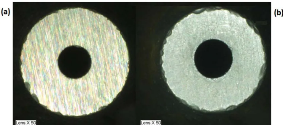
Figure 4.9: Appearance of a machined sheet of PZT
4.3 PZT sheet preparation
This section will show the procedure used for preparing the PZT sheet for the experiments. While the operations involved in the specimen preparation are not particularly complex, attention has to be paid since it is easy to break the sheet because of the brittleness of the material together with the small thickness (0.5 mm) compared to the side dimension (50 mm). Figure 4.10 shows the PZT sheet.
42 The first operation performed is the soldering of a wire on each face of the PZT sheet. In fact, the two faces are silver-covered and work as electrodes. A wire to BNC cable (Figure 4.11) is necessary for the acquisition of data from the sheet during the cut.
Figure 4.11: Wire to BNC cable
The two wires are soldered in the corner of the faces of the PZT sheet (Figure
4.12) in order to limit the occupied area and make it easier to clear the wire from
the workpiece when setting it up for the cut. The functioning of contacts has been tested with a multimeter.
Figure 4.12: Wire soldered to the sheet
Considering the wet working environment, silicon glue has been applied to insulate the soldered area. A layer of orange hot wax has been applied to one side of the sheet: a solid piece of wax was placed on the surface, then melted and spread using a heat gun. The hot wax has the double function of electrically insulate the PZT sheet from the titanium support, thus avoiding short circuits, and strongly bond the workpiece to the supporting plate. Figure 4.13 shows the appearance of the PZT sheet after the preparation procedure.
43
Figure 4.13: PZT sheet after the preparation
To stick the workpiece to the support, a piece of wax has been melted and spread on the titanium plate in the same way used for the PZT sheet. The ceramic has been heated too in order to let the wax melt. The plate and the support has been put in contact and pressure has been carefully applied to eliminate the wax in excess and to have an horizontal surface, paying attention in avoiding the breakage of the PZT sheet. The exceeding wax coming out from the edges has been removed while still melted.
The position of the sheet of PZT on the support is highlighted in red (Figure
4.14a). The electrical wires have been fixed to the support with adhesive tape
(Figure 4.14b).
44
4.4 Signal acquisition and analysis
The electric signal generated by the workpiece during the cutting process has been acquired and analyzed. The evaluated parameters are the Root Mean Square (RMS), the Power Spectral Density (PSD) peak value, the PSD area and the frequency of the peak in the PSD. The signal has been filtered before calculating the parameters. The complete analysis can be found in Chapter 5, the Matlab code used for the calculations in Appendix C and the full tables of the calculated values in Appendix A.
4.4.1 Acquisition procedure
The BNC end of the cable soldered to the PZT sheet has been connected to a Mistras 2/4/6 amplifier (Figure 4.15) in the “single” input plug and the gain has been set to 40 dB. The Mistras amplifier has been linked to a power supply set to 0.3 mA and 28 V as required by the datasheet. Another BNC cable has been used to connect the “output” exit of the amplifier to the acquisition card in the computer. A program written in LabView has been used for the acquisition. The signal has been sampled at a frequency of 2.5 GHz. The resonance frequency of the PZT sheet, which represents the maximum frequency band available for the acquisition, has been calculated and its values was around 1.2 GHz. The Nyquist theorem affirms that the sampling frequency must be at least twice the maximum frequency of interest in the acquisition in order to avoid aliasing, thus the use of a sampling frequency of 2.5 GHz. The files with the acquisition data have been converted in .txt format in order to have the possibility to load them in a computing software. The signal has been analyzed using Matlab, a numerical computing environment.
45
4.4.2 Extraction of the portion of signal used in the calculations
The central portion of signal has been extracted to evaluate the parameters of interest, thus avoiding possible transient events at the beginning and at the end of the cut. Using the code in Appendix C, the following procedure has been used to choose the portion: by zooming in the time domain plot of the signal, the instant corresponding to the beginning of the cut has been found. A length of 2.5 mm of cut has been discarded from that position in order to avoid the transient events and 5 mm of cut has been considered from that point. Since the feed rate changes between the cuts, each signal has a different time length. In order to compare the cuts and considering the same spatial position, the times were converted in physical lengths. Table 4.1 shows the conversion from cut length (millimeters) to signal length (seconds) for each feed rate used in the experiments.
Table 4.1: Length to time conversion according to feed rates Feed rate [mm/min]
10 50 70 300 600
2.5 mm 15 s 3 s 2.14 s 0.5 s 0.25 s
5 mm 30 s 6 s 4.28 s 1 s 0.5 s
To have a clearer idea of the procedure, a practical example is presented in
Figure 4.16, which shows the filtered time domain plot of a cut made using
alumina as abrasive at 50 mm/s. In this case, the machining of the PZT sheet starts at 7.5 s. As shown in Table 4.1, for this specific feed rate the length of 2.5 mm of cut is equivalent to 3 seconds of signal. So, the portion of signal from 7.5 s to 10.5 s is discarded. The considered portion of signal goes from 10.5 s to 16.5 s, as 5 millimeters of cut at 50 mm/min are equal to 6 seconds of signal.
46
Figure 4.16: Procedure for the extraction of the analyzed signal portion
Each starting and ending position has been found by observing the time domain plot of the signal and using as support the times registered during the experiments by means of a chronometer.
4.4.3 Signal filtering
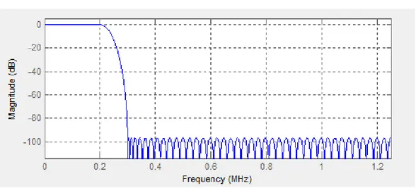
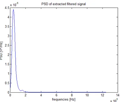
The signal has been filtered using a lowpass equiripple FIR filter (Figure 4.17) with a passband frequency of 200 kHz, a stopband frequency of 300 kHz, a ripple amplitude of 0.1 dB and a stopband attenuation of 100 dB designed using the Matlab Filter Design and Analysis tool (fdatool). The passband and stopband frequencies have been chosen by looking at the PSD graphs (see Section 4.4.6 for the details about the PSD calculation) of the unfiltered signal and finding where the signal energy was present as in the example shown in Figure 4.18.
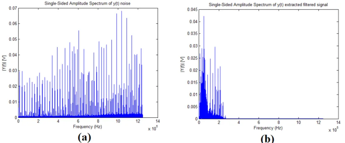
Figure 4.19 shows a comparison between the time domain plot of the unfiltered
signal (Figure 4.19a) and filtered signal (Figure 4.19b) obtained in a cut using garnet as abrasive, an abrasive mass flow of 100 g/min and a feed rate of 300 mm/min.
47
Figure 4.17: FIR pass low filter
Figure 4.18: PSD of a cut made with garnet, feed rate = 300 mm/min, abrasive
![Figure 3.13: Material removal mechanisms by solid particle impact a) microcutting b) cracking [27]](https://thumb-eu.123doks.com/thumbv2/123dokorg/7501954.104552/42.892.239.696.380.610/figure-material-removal-mechanisms-particle-impact-microcutting-cracking.webp)
![Table 4.2: Recommended cut-off [51]](https://thumb-eu.123doks.com/thumbv2/123dokorg/7501954.104552/62.892.197.735.747.970/table-recommended-cut-off.webp)
![Figure 5.15: Filtered signal PSD peak frequency vs Abrasive mass flow at fixed feed rate 00.0000020.0000040.0000060.0000080.000010.0000120.0000140.0000160.000018 0 20 80 80 200Amplitude [V^2/Hz]](https://thumb-eu.123doks.com/thumbv2/123dokorg/7501954.104552/77.892.168.753.232.554/figure-filtered-signal-frequency-abrasive-fixed-rate-amplitude.webp)