UNIVERSITÀ DEGLI STUDI DI PISA
FACOLTÀ DI INGEGNERIA
Dipartimento di Ingegneria Aerospaziale
Tesi di Laurea in Ingegneria Aerospaziale
MODEL DRIVEN DESIGN DEFINITION FOR A CIVIL
AIRCRAFT DURING GROUND OPERATIONS
Relatori:
Prof. Ing. Eugenio Denti Prof. Ing. Attilio Salvetti Ing. Daniele Fanteria Prof. Ing. Sanjiv Sharma Ing. Alessandro Giazotto
Candidato:
Leonardo Vivarelli
Abstract
For Airbus, the System of interest is the aircraft as an integrated whole. Airbus aircrafts operates in the World Air Transportation System, the containing System. The Aircraft has been analyzed starting from a top-level concept. A systematic functions definition has been carried out, as consequence of the two main Aircraft functions (move from departure to arrival and carry payload), bearing in mind the environment the A/C is operating in, and several other considerations. The picture has been completed keeping in mind also all the constraints the aircraft has to deal with and the parameters, which drive the design from a performances perspective. One of the major challenges facing Airbus’ engineers today is the smooth and timely integration and test of all the complex systems on the final Aircraft. This work make of the rigor and formalism one of its strength and thus wants to provide a methodology, to give a response to address this problem. The static model has been build using the SysML (Systems Modelling Language), a new modelling language that is supposed to became the standard for description and specification of complex systems. The strength of SysML is not in it that it is a standard or a tool, but that it is a language. A language similar to a circuit diagram used to describe an electronic component or a formula describing a complex mathematical problem.
The static model forms the specification for the dynamic model, through which is possible to carry out performance prediction analysis, trade off studies, and other activities.
Acknowledgements
I would like to thank professor Eugenio Denti, Professor Attilio Salvetti and Ing. Daniele Fanteria from Dipartimento di Ingegneria Aerospaziale “L. Lazzarino” – Universita’ degli studi di Pisa for giving me the opportunity to prepare this thesis at Airbus UK, and Airbus for supporting it.
I am grateful to Airbus UK Limited for the opportunity they have given in enabling me to carry out my research and prepare this thesis within their facilities. I would like to express my sincere gratitude and thanks to Mr. Sanjiv Sharma for carefully reviewing this thesis, and to Alessandro Giazotto and Franco Calvanese for their constant support during the project.
A special thanks to Mr. Alvery Grazebrook, who has been a fantastic tutor, introducing me to and guiding me through the complex world of modelling languages.
I would also like to express my gratitude to everybody who has provided me with their feedback and support during this research activity: Andy Bird, Luke Bagnall, Bjoern Kirchhoff, Linda Agoudjil, Andy Thomas, Etienne Coetzee, Eve-Lise Guillebault, Luke Spencer, Terry Frost, Simon Hancock and Gianluca Verzichelli. A sincere thanks to Laura for all her patience, support and understanding, and to my parents, for everything they have done for me throughout my studies.
I would also like to thank all my friends, without whom I could never have reached this objective; those who have shared with me the pleasure (and the fatigue) of my studies: Valentina, Andrea, Giovanni and Federico, and also day-to-day life: David, Tommaso, Emanuele, Paolo, Angelica, M.Rosaria and finally all those whom I have not mentioned here.
List of Contents
LIST OF FIGURES... VII
ACRONYMS AND NOMENCLATURE ...IX
FOREWORD... X
1
INTRODUCTION ... 1
2
SYSTEMS ENGINEERING AND OPERATIONAL
FRAMEWORK ... 12
2.1 INTRODUCTION... 12 2.2 SYSTEMS ENGINEERING... 12 2.3 OPERATIONAL FRAMEWORK... 183
REQUIREMENTS ANALYSIS... 21
3.1 INTRODUCTION... 21 3.2 ANALYSIS... 21 3.3 SYSMLREQUIREMENTS DIAGRAM... 24 3.4 CVB REQUIREMENTS... 263.4.1 Customers Needs Collection ... 26
3.4.2 Customers Needs ... 28
3.5 AP2161AIRCRAFT FUNCTIONS DEFINITION PROCESS REQUIREMENTS. 30 3.6 TLARREQUIREMENTS... 30
3.7 ATA32TLSRDREQUIREMENTS... 31
3.8 CERTIFICATION SPECIFICATIONS FOR LARGE AIRPLANES CS25 ... 31
3.9 AERODROME DESIGN AND OPERATIONS STANDARDS 2005... 31
4
STATIC MODEL ... 33
4.1 INTRODUCTION... 33
4.2 METAMODEL... 34
4.3 CONCEPT AND OPERATIONAL CONTEXT... 39
4.4 PROBLEM DEFINITION... 43
4.5 PHASES OF FLIGHT... 44
4.6 AIRCRAFT FUNCTIONS... 46
4.7 RELATIONSHIPS... 50
4.8 USE CASE SPECIFICATION:ACTIVITY DIAGRAM... 51
4.9 USE CASE SPECIFICATION:OBJECT SEQUENCE DIAGRAM... 57
4.10 PARAMETERS... 59
4.10.1 Engine Position - constraints ... 61
4.10.2 Wing Position - constraints... 62
4.10.3 LG Position – constraints ... 63
4.11 LINK OF THE PARAMETERS TO THE MANEUVERABILITY... 69
4.12 EXTERNAL RELATIONSHIPS... 73
Table of Contents 4.14 THE GLOBAL VIEW... 79 4.15 CONCLUSIONS... 81
5
DYNAMIC MODEL... 82
5.1 INTRODUCTION... 82 5.2 DYNAMIC SIMULATION... 82 5.3 PRIOR ART... 845.4 LINK BETWEEN STATIC AND DYNAMIC MODEL... 85
5.5 EXAMPLE OF DYNAMIC MODELS... 87
6
CONCLUSIONS ... 90
7
REFERENCES ... 96
APPENDIX A - SYSTEMS MODELLING LANGUAGE
(SYSML) ... 98
A.1INTRODUCTION... 98
A.2A BRIEF HISTORY... 98
A.3GENERAL ARCHITECTURE... 100
A.4STRUCTURAL CONSTRUCT... 102
A.4.1 Class Diagram... 103
A.4.2 Assembly Diagram... 103
A.4.3 Parametric Diagram... 104
A.5BEHAVIORAL CONSTRUCTS... 105
A.5.1 Activity Diagrams ... 105
A.5.2 Sequence diagram... 106
A.5.3 State Modes diagram ... 106
A.5.4 Use Case diagram... 107
A.6OTHER DIAGRAMS... 107
A.6.1 Requirements diagram ... 107
A.6.2 General Graphics diagram ... 108
A.7PARTNERS... 109
APPENDIX B - ARTISAN STUDIO® 6.0 ... 110
APPENDIX C – INTERVIEW GUIDELINES... 114
APPENDIX D – MODELLING ASSUMPTIONS DOCUMENT
(FOR THE ADAMS BASELINE MODEL FOR GROUND
MANOEUVRABILITY AND BRAKING PERFORMANCE). –
CONTENTS... 118
List of Figures
FIGURE 1-1-AN EASY SYSML EXAMPLE... 5
FIGURE 1-2-THESIS WORK STREAM... 9
FIGURE 1-3-BASIC PROCESS PATTERN... 11
FIGURE 2-1-SYSTEMS ENGINEERING PROCESS... 16
FIGURE 2-2-THE SYSTEM ENGINEERING PROCESS APPLIED TO THE V-CYCLE... 17
FIGURE 3-1-CONSTRAINT PACKAGE EXPLORER PAN... 23
FIGURE 3-2-EXAMPLE OF REQUIREMENT... 24
FIGURE 3-3-INTERVIEW OUTPUTS... 27
FIGURE 3-4-TREE DIAGRAM OF CUSTOMERS’NEEDS... 29
FIGURE 3-5-NUMBER OF CHANGES AGAINST TIME... 30
FIGURE 4-1-METAMODEL... 35
FIGURE 4-2-NESTED PACKAGES... 38
FIGURE 4-3-CONCEPT DIAGRAM... 40
FIGURE 4-4-OPERATIONAL CONTEXT... 41
FIGURE 4-5-ASSEMBLY DIAGRAM... 42
FIGURE 4-6-FLIGHT'S PHASES... 45
FIGURE 4-7-PHASE DESCRIPTION... 45
FIGURE 4-8-USE CASE DIAGRAM -TOP LEVEL A/CFUNCTIONS... 47
FIGURE 4-9-PEOPLE PACKAGE... 48
FIGURE 4-10-CASE STUDY... 49
FIGURE 4-11-OBJECTED ORIENTED APPROACH... 50
FIGURE 4-12-DIAGRAMS GENERATION FROM A USE CASE... 52
FIGURE 4-13-INTERACTION OVERVIEW DIAGRAMS... 53
FIGURE 4-14-SWIM LANE DIAGRAM... 55
FIGURE 4-15-GRAPHICAL INTERFACE FOR A CLASS... 56
FIGURE 4-16-CLASS:ATTRIBUTES AND OPERATIONS... 57
FIGURE 4-17-OBJECT SEQUENCE DIAGRAM... 58
FIGURE 4-18-RELATIONSHIP BETWEEN TOP-LEVEL PARAMETERS AND USE-CASE. 60 FIGURE 4-19-RELATIONSHIP DESCRIPTION... 60
FIGURE 4-20-ENGINE POSITION (CONSTRAINTS) ... 62
FIGURE 4-21-CLASS DIAGRAM FOR WING POSITION. ... 63
FIGURE 4-22-PITCH AND ROLL RESTRICTIONS... 64
FIGURE 4-23-TURNOVER ANGLE... 65
FIGURE 4-24- LM AND LN DEFINITION... 67
FIGURE 4-25-LANDING GEAR GEOMETRIC CONSTRAINT ( PLAN VIEW ) ... 68
FIGURE 4-26-LANDING GEAR GEOMETRIC CONSTRAINT ( FRONT VIEW )... 68
FIGURE 4-27-LANDING GEAR GEOMETRIC CONSTRAINT (ELEVATION VIEW)... 69
FIGURE 4-28-RELATIONSHIP FOR MAIN LG PARAMETERS AND CONSTRAINTS... 70
FIGURE 4-29-RELATIONSHIP IN A TEXTUAL FORM... 71
FIGURE 4-30-ENGINE POSITION:CONSTRAINTS AND MANOEUVRABILITY EFFECTS71 FIGURE 4-31-PARAMETRIC DIAGRAM... 72
FIGURE 4-32-RELATIONSHIP BETWEEN CIVIL AIRCRAFT AND AIRPORT STRUCTURE ... 73
FIGURE 4-33-AIRCRAFT /PAVEMENT RELATIONSHIP... 74
List of Figures
FIGURE 4-35-RUNWAY CLASS DIAGRAM... 77
FIGURE 4-36-TAXIWAY CLASS DIAGRAM... 77
FIGURE 4-37-REFERENCE TO THE ICAO AERODROME DESIGN MANUAL... 78
FIGURE 5-1-A SINGLE STATIC MODE CAN GIVE RAISE TO MORE THAN A DYNAMIC MODELS... 86
FIGURE 5-2-GROUND MANOEUVRABILITY DYNAMIC MODEL... 88
FIGURE 5-3-EXTENSION/RETRACTION DYNAMIC MODEL... 89
Acronyms and Nomenclature
A/C Aircraft
ACN Airport Classification Number BSCS Braking and Steering control System
CG Centre of Gravity
CVB Common Virtual Bird
EIS Entry into Service
FAA Federal Aviation Authority FDD Functions Description Document FRD Functions Requirements Document ICAO International Civil Aviation Organization INCOSE International Council on Systems Engineering
JAA Join Aviation Authority
LG Landing Gear
LGS Landing Gear Systems
M&S Modelling and Simulation
MASP2 Modelling and Simulation Phase two
MBE Model Based Engineering
NWS Nose Wheel Steering
PTS Purchase Technical Specification
QFD Quality Function Deployment
RWY Runway
SDD Systems Description Document
SE Systems Engineering
SRD Systems Requirements Document
SysML System Modelling Language
TBD To Be Defined
TLAR Top Level Aircraft Requirements
TLSDD Top Level System Description Document TLSRD Top Level System Requirement Documents
TWY Taxiway
UML Unified Modelling Language
VOC Voice Of Customer
Foreword
Foreword
Why is a common framework important in the design of complex systems? What is the value of such a framework? Where and how should the people use such a framework? These are the key questions that arise when one aims to conduct work to transform a human need to technical requirements. After all, a design process is primarily about transforming human needs to engineered solutions that can be manufactured, operated, maintained, supported and eventually retired.
What are the sources of complexity? In order to meet the needs, the realisation of the engineered solutions requires people from many disciplines to work collaboratively. The many disciplines are needed because the functionalities required cannot generally be met by one engineering discipline. Further, the different stakeholders have different needs that may change during the design life cycle. Some of the sources of complexity are due to changing requirements and uncertain or disparate needs.
Each discipline has its own language, viewpoints and perspectives. Trying to link them together to have a coherent picture for each stakeholder becomes another source of complexity. When the results of the collaborative work is integrated into the engineered solution, it gives rise to emergent properties, capabilities and behaviours; often intended. What happens if the are unintended? We need to be able to discover them earlier and mitigate them.
A common framework is then needed to guide and evaluate the design progress through the various levels of granularity that make up the solution. In effect, the framework provides a consistency check between the different efforts to produce a coherent design. This is one important aspect needed in the design of complex systems.
In this thesis, the author makes a case for a common framework. The author chooses a case study to illustrate the different aspects that need to be supported by
such framework. He then introduces the SysML (Systems Modelling Language) as a possible implementation of a common language. Through the case studies, some artefacts of the language are explored and an attempt is made to answer questions raised above.
The work presented here is an introduction to a new language, and a recognition that for any framework or language to be common requires a level of investment, primarily in the development of the team of people who will conduct the work. Sanjiv SHARMA
"The whole is more than the sum of its parts."
1
Introduction
The Airbus Mission
“Airbus is one of the world's leading aircraft manufacturers, and it consistently captures approximately half or more of all orders for airliners with more than 100 seats.
Airbus' mission is to provide the aircraft best suited to the market's needs and to support these aircraft with the highest quality of service. The Airbus product line comprises 14 aircraft models, from the 100-seat single-aisle A318 jetliner to the 555-seat A380 - which will be the largest civil airliner ever when it enters service in 2006.”1
Problems to be solved: System Complexity and Flow of information
The Aircraft design takes almost a decade from the first conceptual stage to the Entry Into Service (EIS). During all these years, engineers face and solve a lot of problems and questions. These problems, arising generally from customers’ needs, lead to an improvement in functionality, enhancement of safety and better reliability as well, but, at the same time, they highly increase the system complexity.
It is generally agreed that increasing complexity is at the heart of the most difficult problem facing today’s systems of architecting and engineering. The greater is the complexity, the greater is the difficulty. It is important, therefore, to understand what is meant by system complexity if architectural is to be made in dealing with it. As might be expected, the more elements and interconnections, the more complex the architecture, and the more difficult the system-level problems.
Rates of advance in the computer and information sciences have further made it possible to use software to address the implementation of complexity. However, this brings new challenges for good design and test of these functionalities. The advent of smart, software intensive systems is producing a true paradigm shift in
1
Introduction
the system design. Particularly susceptible to these changes are systems which depend upon electronics and information systems, and which have not been characterized by the formal partnership with architecting that structural engineering has addressed.
Airbus is a company with over 55.000 employees. Airbus production and support facilities are located around the world, from Europe, through North America to Asia Pacific. Furthermore, all suppliers have to be considered in the extended enterprise concept. The unambiguous flow of information to enable the extended enterprise to operate effectively needs to be addressed.
Alongside of the systems complexity therefore, engineers have often to face the problem of communication and organization. Exchange of information with suppliers, customers, as well as other stakeholders, can lead to various misunderstanding and misinterpretation because of the different engineering language, the people’s background, and the different perspective of the system design. Late detected design errors could result in increased cost, schedule slips, reduced capability and indeed cancelled programs.
A well-designed, systematic model based approach to the design can greatly reduce both these problems.
Model Based Engineering
“For more than a decade Airbus has made increased use of computer-based M&S (Modelling and Simulation) technologies in its LGS design activities. Originally adopted to reduce physical test costs by providing performance predictions, this technology was soon used to detect specification defects. Market pressures are now creating an imperative for optimisation of the complete LGS (Landing Gear Systems), as an integral part of the aircraft, despite the inherent complexity of this task. Although Airbus has begun to use M&S to support design optimisation, this new application is still in its infancy. More extensive and timely use of computer-based M&S technologies will help Airbus satisfy these market needs.”2
2
Model Based Engineering - MBE - focuses on the processes that need to take place to ensure that the models are of high quality as these models represent the system under design. MBE should take into account all regulations, and define how models could be used within a Systems Engineering framework.
Rationale behind the work
The thesis is aimed at giving an example of a new concept of the design, in a structured and formalized way. The civil A/C is the “System of Interest”. It has been analyzed from different points of view in order to define all the relationships necessary to specify the next level down of details and so carry on in the design. The relationship between the aircraft itself and external entities in place give rise to many derived requirements. Functions are thus created from all the requirements. Grouping these functions will give rise to objects. When functions are allocated for implementation objects implement them. Functions are abstract concepts, whilst objects are concrete entities. The idea of object suggests that there is a structure behind it. The structure is realized in order to accomplish the functions it is meant to. It is the description of the object; it is the function (or group of them) made real. Its behaviour is defined by parameters (things that are controllable) and constraints (things that the function must or must not do). Parameter and constraint therefore must be analyzed.
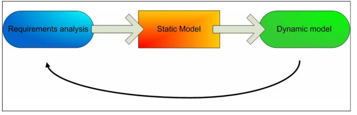
This is the path followed in the thesis: The requirements analysis, the transformation of them in functions, and finally the implementation of these “static concepts” in a simulation environment.
Follows a brief description of the work and its context and the contents of each chapter the thesis.
Context of the work
This study has been done as a part of MASP2 (Modelling And Simulation Phase Two), with application deployed to CVB (Common Virtual Bird) Pilot Project II – Aircraft on Ground Operations (A/C on GO).
Introduction
This is an international project that involves the extended enterprise (i.e. all Airbus entities and suppliers) and which is aimed to improve A/C design with aid of Modelling and Simulation techniques. One of the objectives of the A/C on GO is to “extend the modelling and simulation of the Landing Gear System as an integral subsystem of the operational A/C during Taxi Out phase”.
For Airbus, the System of interest is the aircraft as an integrated whole. Airbus aircrafts operates in the World Air Transportation System, the containing System. The Landing Gear for example is a subsystem, which, in turn is composed of different subsystems.
The Aircraft has been analyzed starting from a top-level concept. A systematic functions definition has been carried out, as consequence of the two main Aircraft functions (move from departure to arrival and carry payload), bearing in mind the environment the A/C is operating in, and several other considerations. The picture has been completed keeping in mind also all the constraints the aircraft has to deal with and the parameters, which drive the design from a performances perspective. One of the major challenges facing Airbus’ engineers today is the smooth and timely integration and test of all the complex systems on the final Aircraft. This work make of the rigor and formalism one of its strength and thus wants to provide a methodology, to give a response to address this problem. The model has been build using the SysML (Systems Modelling Language), a new modelling language that is supposed to became the standard for description and specification of complex systems. The strength of SysML is not in it that it is a standard or a tool, but that it is a language. A language similar to a circuit diagram used to describe an electronic component or a formula describing a complex mathematical problem.
As example instead of writing the following: “The system consists of two components, namely component A and component B. There is an interface between component A and component B. Component B provides for the interface to component A” the following (assembly) diagram provides the same detail much more effective.
Figure 1-1 - An easy SysML example
Structure of the work
Five chapters plus two appendixes make the work. What follow is a brief description of them, highlighting the key aspects analyzed in details in the chapters themselves.
Chapter 1: This chapter contains an introduction to the general concepts this
study is based on. It starts with the definition of what is Systems Engineering and a description of which is the method adopted by Systems engineering community, and how does this method is applied in Airbus; afterwards, the architectural framework’s concept is presented and it is explained how and what Airbus can benefit from the set-up of such a framework. These arguments are explained in the first chapter because they are the foundation all the work is build on. The aim of the chapter is to make people more familiar with these concepts witch can otherwise appear a bit abstract at the beginning.
Chapter 2: In the second chapter are analyzed the requirements that could be
useful for a correct development of the system. There are many requirements that should be taken into account starting from top-level concept and going down to levels that are more detailed. In this thesis has been used only a part of them, trying to show what are the potential benefits in requirements managing.
Introduction
The requirements referring to modelling and simulation activities come from the CVB scoping phase as requirements expressed by the interviewed stakeholders. The requirements, captured and handled in the first part of the work using the Quality Function Deployment (QFD) techniques, have been converted in customers’ needs. Those customers’ needs represent the guideline, which drive the entire project.
The requirements concerning the technical aspects come from different sources:
• The AP2161 Aircraft Function Definition Process,
• The ATA32 A380 Top Level System Requirements Document (TLSRD).
• Certification Specifications for Large Aeroplanes (CS 25).
All these requirements have been used in the model as constraint to the design. It has been tried to create a link between design decisions and requirements, and to grant their traceability.
Chapter 3: This is the main chapter of this study, the core of the thesis. It
contains the development of the static model. The static model is an ensemble of all information necessary to describe a system. It gives the system specification for dynamic model, containing all assumptions made, as initial conditions, boundary conditions etc. Static model is not related with the tools used to implement a simulation of the system. It describes what the system is intended to do. The model is therefore the description of the system. The static model is synonymous with a descriptive model. The static model starts with an introduction of the “System of Interest” – the Civil Aircraft – and all the “external” entities and actors it is related to (environment, passengers, … ) . Defining all the relationship the civil Aircraft has with them it is built a consistent picture which contains all the needed information that allow the designer to address the next level down in the design lifecycle. The study is focussed on the steering function, that is to say the need of the Aircraft to manoeuvre whilst carrying on ground phases. It is not a task only of the steering system: other systems can play a fundamental role in it. These aspects however must be taken into account in the design of the steering
device. Along with the description of the model, it has also shown the main futures of SysML in order to make the diagrams clearer and more understandable and spread between readers the knowledge of this new standard language.
Chapter 4: As stated above chapter 3 is the core of the thesis. Chapter 4 is the
natural consequence of Chapter 3: the deployment of the static model in the simulation environment, and the verification and validation of the model. All the information contained in the static model, used in a simulation environment, gives the dynamic model, in which all variables changing in time. The traceability between the descriptive model and the dynamic has taken into account. This is one of the most important and innovative outputs. The dynamic model is then an earlier representation of what a system will do. In this thesis is shown only the link between this Static and the Dynamic model. The detailed of how to build a new dynamic model starting from the static model will be developed in the CVB pilot project 2, and are out of the scope of this work.
Chapter 5: This is the last chapter of the thesis and it is dedicated mainly to the
benefits and the future works that can arise from this thesis. Give people a common understanding of the project and a common source of information are two of the main benefits that can be extracted by this work, which match the need of having a systematic, formalized way of designing since the beginning of the project. The most important future work is that potentially this work can be the starting point for a new way of doing simulation and setting up the models (i.e. Adams models or Matlab-Simulink models), with a great reduction in time needed to set up the models. The thesis is aimed to be a framework, so something, which is invariant. Modeller should then already know where to put things.
The report contains also four appendixes at its end. These parts complete and integrate all it is explained in the five chapters above. Appendix A is a general, detailed description of SysML. It contains a bit of background, the rationale that pushed towards the realization of SysML and its relationship with UML (Unified Modelling Language). Besides, it holds the general structure of SysML and a short paragraph about each of the SysML diagram.
Introduction
Appendix B, on the other side, explains in deep the tool that has been used to build up the static model. The official explanation available also on the Artisan website follows an introduction made by the author. Some screenshot contained in chapter 3 also help to explain and shows the interface provided by the tools to the user. Appendix C shows the interview guideline that has been used during the first part of the CVB project. It is the first step to apply the QFD methodology to the project. Appendix D contains the contents of the “Modelling Assumptions Document for the ADAMS Baseline Model for Ground Manoeuvrability and Braking Performance.
Literature and Bibliography
At present, there is limited number of articles or books written on this subject, as it is a very new one. The articles have generally the aim of spread the knowledge of SysML across the systems engineering community, showing different applications, explaining different models (petrol station or washing machine for example) and how does SysML support the specification of such models. Artisan staff has written most of them. Models anyway are not explained in deep. They are definitely interesting articles, but the reader should have a background and be familiar with SysML at least in its principles.
The SysML specification instead is a useful means to be familiar with the language as it explains all the meanings of each single symbol. It is probably not something to read to learn the language, but it is something to refer to while building up the model.
The web offers useful information about SysML. The official website (www.sysml.org) hold the specification and the latest updates, plus the link to the SysML forum, which is an important source of information.
There are no books yet which treat in comprehensive way SysML matters. The author has based mainly on reading book to get familiar with the tool, but all of them are about UML. They are UML Distilled written by M. Fowler and Business modelling with UML written by H.E Eriksson and M.Penker.
Other information contained in the thesis has been extracted by different articles, suggested by key expert in the field or found on the web. They are mainly about architectural framework, among them it worth reminding the Zachman framework, and the Systems Engineering concepts and processes.
All the sources are listed in the references section at the end of the thesis.
Conclusion
This work is aimed to give an example on an innovative concept of design. It shows how the use of a system definition language and the realisation of a framework can lead to a more structured approach to the design, from the early stages. The unified language reduces problems of communications and so potential misunderstanding. The framework guarantees a robust base for future development and changes, and enables the complexity of the architecture to be handled.
The framework is an invariant entity that can be used by all the programmes. Once the framework is in place the link between the requirements and the dynamic model is automatic. This aspect represents the major improvement achieved. If there is a change in the requirements, what changes is the flow of information, which probably leads to a change in the final behaviour of the product.
Introduction
The work is made using a top-down approach. The intention of the top-down approach is to have a full picture of interactions at every level. In the top-down approach all the interactions (for instance integration between systems) are taken into account. If a bottom-up approach was used instead, the full picture would have been missed and the problems would have been probably founded late in the project, with a foreseeable rise in terms of cost and time.
It is a new approach and design to describe the model looking at the physical and computational aspect at the same time. It is key to note that the description of model is synonymous with the description of the system.
This kind of formalization, has been made in this work at A/C level, but could reused, changing some boxes at each level down in the design cycle, that is to say for systems, subsystems, components.
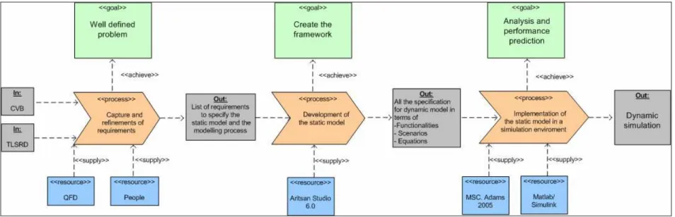
Figure 1-3 shows the basic process pattern of the work. It this figure, the main activities carried out (arrow shape) are shown and for each of them are shown the inputs on the left hand side, the outputs on the right hand side, the resources and the goals. That diagram helps to have a clearer idea of the process in place and shows all the information needed for its development.
Systems Engineering and Operational Framework
2
Systems Engineering and Operational
Framework
2.1
Introduction
Two fundamental concepts that help to understand and contextualize all the work done are explained in this chapter of the thesis: The Systems Engineering and the Operational Framework.
After the INCOSE definition, which introduces Systems Engineering, it is explained the System Engineering management as an activity made up by three major activities: The development phasing, the System Engineering process and the life cycle integration. The System Engineering process is the key aspect to be shown and it is analyzed further in details. Afterwards the concept of Operational Framework is described, highlighting the main aspects of it, especially the fact that it is invariant against any engineering disciplines, tools or methodologies. This section forms a necessary background to understand the work done in the thesis.
2.2
Systems Engineering
This definition of the International Council on Systems Engineering (INCOSE), explains, using very simple words, the scope of Systems Engineering.
“Systems Engineering is an interdisciplinary approach and means to enable the realization of successful systems. It focuses on defining customer needs and required functionality early in the development cycle, documenting requirements, then proceeding with design synthesis and system validation while considering the complete problem:
• Cost & Schedule
• Test
• Manufacturing
• Training & Support
• Operations
• Disposal.
Systems Engineering integrates all the disciplines and specialty groups into a team effort forming a structured development process that proceeds from concept to production to operation. Systems Engineering considers both the business and the technical needs of all customers with the goal of providing a quality product that meets the user needs”. 3
The realization of successful systems is the primary objective that drives Airbus projects. Although the words are simple, the meaning is wide-ranging, and the activities are not easy to implement.
Systems engineering management is the most important aspect and it is worth explaining it more in details.
System engineering management is accomplished by three major activities:
• Development phasing that controls the design process and provides baselines to coordinate design efforts.
• A system engineering process that provides a structure for solving design problems and tracking requirements follow through to the design effort.
• A Life cycle integration that involves the customers in the design process and ensure that the system developed is viable throughout is life
Each of these activities is necessary to achieve proper management of development effort.
Phasing has two major purposes: it controls the design effort and it is the major
connection between the technical management effort and the overall acquisition effort. It controls the design effort by developing design baselines that govern
3
Systems Engineering and Operational Framework
each level of development. It interfaces with the acquisition management by providing key events in the development process where design viability can be assessed. The feasibility of the baselines developed is a major input for acquisition management milestones decisions. As a results, the timing and coordination between technical development phasing and the acquisition schedule is critical to maintain a healthy acquisition program.
The system engineering process is the heart of system engineering management. Its purpose is to provide a structured but flexible process that transforms requirements into specifications, architectures and configuration baselines. The discipline of this process provides the control and traceability to develop solutions that meet customer needs.
The system engineering process may be repeated one or more times during any phase of the development process.
Life cycle integration is necessary to ensure that the design solution is feasible
throughout the life of the system. It includes the planning associated with the product and process development, as well as the integration of multiple functional concerns into the design and engineering process. In this manner, product cycle-times can be reduced and the need for redesign and rework substantially reduced. Development usually progresses through distinct levels or stages:
• Concept level, which produces a system concept description (usually described in a concept study).
• System level, which produces a system description in performance requirement terms.
• Subsystem/component level, which produces first a set of subsystem and component product performance descriptions, then a set of corresponding detailed descriptions of the products’ characteristics, essential for their production.
As it has been explained in the introduction this work is made at concept level. It is a process of reverse engineering, through which it is tried to investigate how this approach could have been used, and which are the benefits that it could have
brought about. The systems engineering process is the real focus of this thesis. It useful therefore, to analyze the steps of the process more in details.
The systems engineering process aims to be a comprehensive a top-down, iterative and recursive problem solving process, applied sequentially through all stages of development; it is used to:
• Transform needs and requirements into a set of system product and processes description (adding value and more details with each level of development).
• Generate information for decision markers
• Provide input for next level of development
The fundamental system engineering activities are Requirements Analysis, Functional Analysis /Allocation, and design Synthesis. Systems engineering controls are used to track cost and schedule, track technical performance, verify requirements are met, and review/audit the progress. Figure 2-1 represents a flow diagram of a typical Systems engineering process.
Systems Engineering and Operational Framework
Figure 2-1 - Systems Engineering Process
The system engineering process is applied to each level of system development, one level at time, to produce these descriptions commonly called configuration baselines. This results in a series of baselines, one at each development level. This baseline became more detailed with each level.
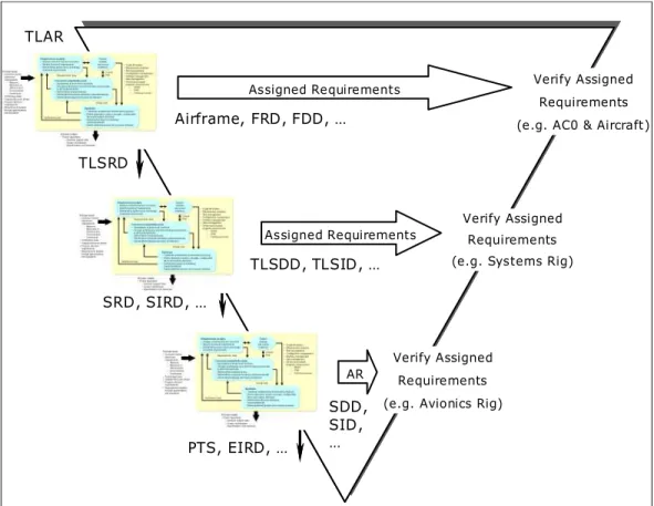
Figure 2-1 shows the systems engineering process applied to each level of the V-cycle.
The V-cycle is used to depict the systems engineering design process, where the left side of the V designates the design phase, and the right side the testing and implementation phase.
TLAR Assigned Requirements Assigned Requirements AR TLSRD SRD, SIRD, … PTS, EIRD, … TLSDD, TLSID, … SDD, SID, … Verify Assigned Requirements (e.g. AC0 & Aircraft)
Verify Assigned Requirements (e.g. Systems Rig)
Verify Assigned Requirements (e.g. Avionics Rig) Airframe, FRD, FDD, … TLAR Assigned Requirements Assigned Requirements AR TLSRD SRD, SIRD, … PTS, EIRD, … TLSDD, TLSID, … SDD, SID, … Verify Assigned Requirements (e.g. AC0 & Aircraft)
Verify Assigned Requirements (e.g. Systems Rig)
Verify Assigned Requirements (e.g. Avionics Rig) Airframe, FRD, FDD, …
Figure 2-2 - The system engineering process applied to the V-cycle
During the system engineering process, architectures are generated to describe, understand and select the most appropriate system. The word “architecture” is used in various contexts, in the general field of engineering. It is used as a general description of how the subsystems join together to form the system. It can be also a detailed description of an aspect of a system. In the system-engineering field this word is used to describe three different aspects:
• Functional Architecture: Identifies and structures the allocated functional and performance requirements.
• Physical Architecture: Depict the system product by showing how it is broken down into subsystem and components.
• System Architecture: Identifies all the products (including enabling products) that are necessary to support the system and, by implication, the
Systems Engineering and Operational Framework
processes necessary for development, production, construction, deployment, operations, support, training and verification.
This work is a functional study that has been made at aircraft level. It is an analysis on what the system is supposed to do, not on how the system will do it. A functional study is fundamental to create innovation, to think about new solutions able to implement the functions that have been identified.
The physical architecture is the logical consequence of a functional analysis but it is not treated in this thesis. The thesis is aimed only at creating a “static description” of everything a designer have to take into account for a correct design. All the factors have to be taken into account from the beginning of the project. Once functions are created they are in place and they are the same until the requirements change. The structure to be realized is therefore a means to realize these functions. That is the reason why the static model is seen as a framework, that is to say something that doesn’t change in the time, something that is invariant, something that has been created, not with the aim to solve the problems at the details level, but to give a wider, common view on the overall design process, to think about problems and their potential solution from a new point of view.
2.3
Operational Framework
In this thesis is shown how the building of a framework helps the design and the model and simulation activities for complex architecture such as a LG and its systems. A framework is something, which contains all the requested information to specify the product, to handle complexity and to provide the community of systems engineers, assistance in building a coherent picture of the system. The Framework is a generic classification scheme for design artefacts, that is, descriptive representations of any complex object. The utility of such a classification scheme is to enable focused concentration on selected aspects of an object without losing a sense of the contextual, or holistic, perspective. In
designing and building complex objects, there are simply too many details and relationships to consider simultaneously.
A Framework that has the characteristics of any good classification scheme, that is, it allows for abstractions intended to:
• Simplify for understanding and communication.
• Clearly focus on independent variables for analytical purposes, but at the same time.
• Maintain a disciplined awareness of contextual relationships that are significant to preserve the integrity of the object.
It makes little difference whether the object is physical, like an aircraft, or conceptual, like an aircraft functions. The challenges are the same. How do you design and build it piece-by-piece such that it achieves its purpose without dissipating its value and raising its cost by optimizing the pieces, sub-optimizing the aircraft.
The framework is a comprehensive, logical structure for descriptive representations (i.e. models, or design artefacts) of any complex object and is neutral with regard to the processes or tools used for producing the descriptions. For this reason, the Framework is helpful for sorting out very complex, technology and methodology choices and issues that are significant both to general management and to technology management.
In other words a framework can be described as:
Simple: It is easy to understand, not technical, purely logical. In its most
elemental form, it has three perspectives: Owner, Designer, Builder, and three abstractions: Material, Function, Geometry. Anybody (technical or non-technical) should be able to understand it.
Comprehensive: It should address the aircraft in its entirety but allow focus in
specific areas where details may be required. Any issues can be mapped against it to understand where they fit within the context of the Enterprise as a whole.
Systems Engineering and Operational Framework
a Language : It enable to think about complex concepts and communicate them precisely taking into account the different disciplines of the stakeholder.
a Planning Tool : It helps you make better choices as you are never making choices in a vacuum. You can position issues in the context of the Enterprise and see a total range of alternatives.
a Problem Solving Tool : It enables you to work with abstractions, to simplify, to isolate simple variables without losing sense of the complexity of the Enterprise as a whole.
Neutral: It is defined totally independently of engineering disciplines, tools or
methodologies and therefore any tool or any methodology can be mapped against it to understand their implicit trade-offs, that is, what they are doing, and what they are not doing.
The Framework for aircraft architecture is just a tool, a tool for thinking and rationalizing. If it is employed with understanding, it should be of great benefit to technical and non-technical management alike, in dealing with the complexities and dynamics of aircraft during concepts, evaluation, marketing, design, prototyping, testing, production, development, operation, support, evolution and retirement.
Any Airbus Architectural Framework must bind operational context, an aircraft as a system, and all its constituent subsystems into a coherent and consistent definition that is not evidently incomplete.
A framework, to be defined and well understood by all the members of the community of systems engineers, must be specified using a System Definition Language a language that aids understanding and provides assistance in building coherent picture of a system construction.
3
Requirements Analysis
3.1
Introduction
A requirement represents the behaviour, structure, and/or properties that a system, component, or other model element must satisfy. The first step in the fulfilment of the design is the clear definition and understanding of what are the requirements that drive the projects. The requirements define the scope of the projects. They define what the customers, or stakeholders expect the system, or the model to do. The clearer are the requirements at the beginning of the project, the easier is to find the way to achieve a good result. They are therefore a fundamental aspect for every project.
3.2
Analysis
In this study different types of requirements have been taken into account, and different sources have been analyzed:
• The requirements coming from CVB A/C on GO which drive the overall project.
• The requirements coming from AP2161 - Aircraft Functions Definition Process - that support the elaboration of the A/C requirements and allocations of function to the A/C architecture.
• The requirements coming from Top Level Aircraft Requirements Document for A380 (TLAR)4.
• The requirements coming from ATA 32 Landing Gear Top Level System Requirements Document for A380 (TLSRD), that drive the design of
4
This document has been used only to extract general requirements, which then could be re-applied to other programmes.
Requirements Analysis
every Landing Gear Systems, and the building of the static model in this specific case 5.
• The requirements coming form the Certification Specifications for Large Aeroplanes - CS 25.
• The requirements coming from ICAO Annex 14, Aerodrome Standards 2005 which defines all the regulation necessary to an airport to be certified, and therefore provide constraints to the A/C designer.
Usually not all the requirements are known at the beginning of the project, but they are discovered as long as the project scope progresses. Some requirements have been just assumed even if not referred to any specific source. This has been done to give an overall view as complete as possible of the model, referring to the constraints section, and because this is a project which packages ideally can be filled by the experts, each one in his or her particular in field.
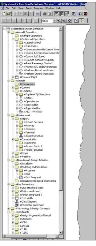
Figure 3-1 shows the explorer pan referred to the “constraints” package. It can be seen all the sub-packages nested in the main one, and also most of the requirements contained in each of them. For some of the requirements it can be also seen what aspect they are referred to.
Requirements are archived as classes, and references to them are frequently made along the description of the static model, in the next chapter. This aspects grant traceability, that is one of the most important aspect and will be discussed later.
5
This document has been used only to extract general requirements, which then could be re-applied to other programmes.
Figure 3-1 - Constraint Package Explorer Pan
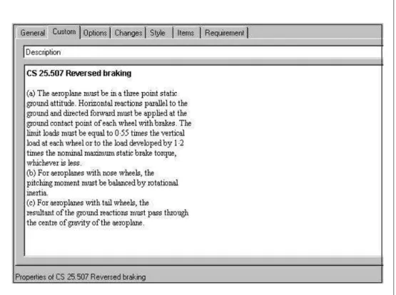
In the description section of each item is quoted the requirement extracted from the documents. The picture below, figure 3-2, illustrates, as an example, the requirements concerning the reversed braking, which is contained in the Certification Specifications for Large Aeroplanes.
Requirements Analysis
Figure 3-2 - Example of Requirement
Reference to this requirement will be finding in the model when Reversed Braking will be studied (not in this work). What is stated in the requirements text shall be satisfied in the reality as well as in the model, which is the true representation of the reality.
3.3
SysML Requirements Diagram
As it has been said before the starting point for any system is its requirements definition. Traditionally, these are large documents provided in printed or electronic form. Additional documents and models sometimes come with them to demonstrate that a system will meet, realise, satisfy and test these requirements. To link the requirements to the models or other documents, engineers use matrices, which can be either in written form or in spreadsheets. Specialist tools for requirements management are often used. These tools worked well for text based documentation, but could not link to models. To address this, some
documents were created where each element in the document corresponded to an element in the model. Other tools combine requirements and modelling together, normally making use of proprietary notation. However, these are specialist Systems Engineering tools and often did not scale well. SysML allows the construction of a new diagram (which was not included in UML) called requirements diagram that is “the SysML support for describing textual requirements and relating them to the specification, analysis models, design models, etc. 6 ”
Requirements specifications can be modelled containing sets of requirements. Each requirement will have attributes to specify the text. Other aspects of a requirement such as its priority, safety critical level, etc. can also be modelled. Requirements can be shared between specification packages. The requirements model includes relationships among requirements and between requirements and other model elements. A derived requirement can be related to one or more source requirements using the trace relationship. A requirement can be related to a model element that is intended to realise or satisfy the requirement.
The requirements model is not meant to replace external requirements tools, but is meant to be used in conjunction with them to increase traceability within the models. It could also be used for modelling the requirements and system for smaller projects. In this thesis is not shown a real requirements diagram, but requirements are modelled and reference to them has been made in many different diagrams.
Traceability in fact is one of the strength that should come out from the model. Every thing is modelled can be referred to specific requirements. This has a double advantage: first of all from a management point of view, because it allows the project to be well organized, which is fundamental especially for large projects. Then, since this work is aimed at being a framework it will be re-applied to new/different projects, and so the designer can immediately check which requirements have been changed, and so which are the models’ aspects that need to be modified.
6
Requirements Analysis
The most important requirements from the list shown above are discussed in the following sections.
3.4
CVB requirements
As stated in the introduction, CVB is a long-term project aimed to improve aircraft design with aid of Modelling and Simulation techniques. The first part of the work has focussed on a formal approach to the requirements’ capture in order to meet the expectations of the project management (Steering Committee). In this phase decision was taken to adopt the QFD methodology to manage the requirements and proceed in the best way. QFD is a method based on a structured approach to enables a development team to specify clearly the customer’s needs, and then to evaluate systematically each proposed activity in terms of its impact on meeting those needs. The rationale behind this choice is that this is a very recent technique, which has proven very effective. QFD is seen as one of the more advanced techniques in the planning and development phases. What is interesting for this works is the first stages of the QFD methodology; this stage is related to requirements capture and their transformation to customers needs. QFD however involves more steps that enable to get the best product that meet customer expectations. The process has been carried out entirely, but it’s out of the scope of this thesis to report.
3.4.1 Customers Needs Collection
The QFD techniques have been used to capture the needs of the stakeholders, and translate them in a list of customers’ requirements. In order to avoid the risk of trying to solve the wrong-defined problem for A/C on GO, have been decided to engage all key stakeholders in the LGS definition trying to cover as much as possible all different departments, and so all different aspects for LG design: Loads, Structure, Systems, Safety, Integration, Performances, etc. Each stakeholder has been interviewed, in order to get his or her needs.
The Interview Guidelines (See appendix C) have been written around a serious of open-ended questions. The term ‘open–ended questions’ refers to questions for which there is not simply a ‘yes’ or ‘no’ answer, but allows explanation of the answer. Such questions encourage the interviewee to provide much more information than a simple “yes” or “no” and to explain the rationale behind them. This kind of questions has been used in the Interview Guidelines because it gives the interviewee as much freedom to elaborate the answer as possible.
After the first set of interviews, the Interview Guidelines had been updated and improved, taking into account the feedback from each interviewee. At the end, four releases have been issued to obtain a final version that is easier to manage and covers the main topics better.
From each interview the following information have been extracted:
• Context
• Voice of Customers
• Statistics
Figure 3-3 shows the fields and the type of information extracted from the questionnaire.
•Q0: Main roles and activities
•Q1: Ground operations phases of interest •Q2: Activities to address these phases
•Q3: Concerns/Issues •Q4: To be
•Q1.1: Rank interest in the ground operations phases
•Q3.1: Level of satisfaction about current situation StatisticsStatistics
Voice of Customers
Voice of Customers
Context
Context
Questions Fields
VoC: Statement made by stakeholders (“raw” data)
Requirements Analysis
The information gathered during the one - to - one interviews represent the “Voice of Customer” (VOC). The Voice of Customer is what the customer says; it is also called “raw data” because often it expresses needs informally. It is what has to be transformed in the customer needs. This process needs to be put in context, to have a clearer view about the interviewee and their activities and so understand better what are their real needs. Some statistics can help to identify the main gaps that need to be addressed. The standard QFD tool to capture the context of VOC is the “Voice of Customer Table” (VOCT). Using it the widest possible range of customer needs is identified and can be understood at a glance.
With the help of the Voice of Customer Table the VOC have been manipulated to obtain the Customers’ Needs. The Customers’ Needs are a statement of benefit that a customer gets, or could get from a product or service. The creation of a common framework to manage complexity design for Landing Gear System is the fulfilment of these needs. Changes in the early stage of the project cost much less than changes in the last stage.
3.4.2 Customers Needs
Once collected, the Customers’ Needs were sorted in a hierarchical structure using the ‘Affinity Diagram’, another powerful tool for organising qualitative information. The hierarchy is built from bottom up, and the relationships between the needs are based on the intuition of the team creating the diagram. As a result of the Affinity Diagram all the 133 customers’ needs collected have been sorted into different groups, as shown in figure 3-4. They are grouped in three main top-level categories (1st Level): Design evolution, Product evolution and Enterprise processes. Each of them is divided in three 2nd Level groups, which are again split-up in lower level categories (3rd Level). The 4th Level contains the Customers’ Needs expressed by the interviewees
Loads Assessment Loads Assessment Design Evolution Design Evolution Tyres Data Loads Prediction Fatigue Spectrum Product Evolution
Product Evolution Enterprise processesEnterprise processes
A/c Usage On Ground Addressing Comfort Environmental Effects Product Integrity Product Integrity Performance Integrity Performance Integrity
V&V and Certification Mgt
V&V and Certification Mgt
Integrated Design Process Problems Prediction Robust Design
Design Definition Performance Prediction Design Evaluation Design Data Provisioning
Project Mgt Project Mgt Resource Mgt Resource Mgt Collaborative Environment Collaborative Environment Requirements Definition Certification V&V Systems Integration Human Factor Issues Safety Issues
Timing (Time Management) Process Management Responsabilities Management Tools Capabilities Skills Management Communication Capabilities Collaborative Working Stakeholder Mapping Operational Scenario Operational Scenario
Model Based Engineering
Model Based Engineering
Loads Assessment Loads Assessment Design Evolution Design Evolution Tyres Data Loads Prediction Fatigue Spectrum Tyres Data Loads Prediction Fatigue Spectrum Product Evolution
Product Evolution Enterprise processesEnterprise processes
A/c Usage On Ground Addressing Comfort Environmental Effects A/c Usage On Ground Addressing Comfort Environmental Effects Product Integrity Product Integrity Performance Integrity Performance Integrity
V&V and Certification Mgt
V&V and Certification Mgt
Integrated Design Process Problems Prediction Robust Design Integrated Design Process Problems Prediction Robust Design
Design Definition Performance Prediction Design Evaluation Design Data Provisioning Design Definition Performance Prediction Design Evaluation Design Data Provisioning
Project Mgt Project Mgt Resource Mgt Resource Mgt Collaborative Environment Collaborative Environment Requirements Definition Certification V&V Requirements Definition Certification V&V Systems Integration Human Factor Issues Safety Issues Systems Integration Human Factor Issues Safety Issues
Timing (Time Management) Process Management Timing (Time Management) Process Management Responsabilities Management Tools Capabilities Skills Management Responsabilities Management Tools Capabilities Skills Management Communication Capabilities Collaborative Working Stakeholder Mapping Communication Capabilities Collaborative Working Stakeholder Mapping Operational Scenario Operational Scenario
Model Based Engineering
Model Based Engineering
Figure 3-4 - Tree Diagram of Customers’ Needs
Not all the collected needs are relevant to the scope of this project7. The relevant ones are those concerning model and simulation activity in relationship with the users’ expectations.
The main advantage of the QFD methodology is that the effort distribution of projects, which are based on a QFD approach, is concentrate in the early design phases. However at the end of the projects a better quality product with a lower expense is guaranteed. Statistic shows that the number of engineering changes per units of time during the design phase reaches a peak about 19 months before the 1st day of production.
There are virtually no changes after that day. Figure 3-5 shows the comparison of the number of changes using a classical techniques and QFD against time.
7
The needs have been collected for the scoping phase of the whole CVB A/C on GO project which perspective is wider than this thesis. CVB is a long-range project with a schedule of 5 years. It is divided in work-packages, and each work package is divided in turn in work streams. This thesis is a work stream of the work-package called “Model specification and build”
Requirements Analysis
Number of Changes
Time
20 - 24
months
14 -17
months
1 - 3
months
1st day of
production
QFD Development
Figure 3-5 - Number of changes against time
3.5
AP 2161 Aircraft Functions Definition Process Requirements
This document has been used as guide to extract a set of primary functional requirements at Aircraft level. These are requirements that specify aircraft mission and they are absolutely general, valid for every civil A/C.
3.6
TLAR Requirements
The same kinds of information have been extracted from the TLAR (Top Level Aircraft Requirement). However this document is programme specific, so the information had to be generalized before their use.
3.7
ATA32 TLSRD Requirements
The ATA32 Top Level Systems Requirements Document for A380 identifies all the applicable requirements and design goals for the design of the A380 LG System.
Some requirements have been extracted from this document, and used build up the static model.
The requirements taken into account are those relative to ground manoeuvrability, according to the scope of the project, which address the taxi-out phase.
The choice of using the requirements valid for the A380 LG system is due to the fact that, as stated in the introduction, this work is aimed to be a reverse engineering process to show how this design concept has been applied.
3.8
Certification Specifications for Large Airplanes CS 25
This documents provided a lot of information concerning all the aspects to be taken into account during ground operation as it can be seen from picture 3-1. The collection of requirements contained in this document is really wide, ranging from safety, to comfort, loads, performances etc.
Some of those requirements are concerning components (so a lower level of those this work is referred to) as brakes, tyres and wheel but it is necessary to take them into account since the beginning to have a complete view of the model it is going to be built.
3.9
Aerodrome design and operations Standards 2005
This document contains the standards that prescribe the physical characteristics and obstacle limitation surfaces to be provided for at aerodromes, and certain facilities and technical services normally provided at an aerodrome. It has been
Requirements Analysis
used mainly, to extract the standard layout of the aerodromes (i.e. intersection between runway and taxiways) in order to specify the manoeuvre to be completed.
The requirements collection is the starting point to build up the static model: the input from CVB to control the overall process, the input from TLSRD and AP2161 to design the static model.
The methodology adopted assures that the risk to have missing some requirements is minimised.
4
Static Model
4.1
Introduction
In this chapter the author gives examples of how SysML can support the design of complex systems, starting at a conceptual stage, and continuing through the layers of the design cycle. The author shows how a model of a complex system can be defined in a systematic way. The reader should bear in mind that the context of the examples is an aircraft during ground operation.
After an introduction regarding general concepts, the work will be focused on the taxi-out phase, which is the leading phase for CVB Pilot Project 28. Much functionality is required from an airplane during ground operation. The ones chosen for a detailed analysis are those relating to the lateral control of the airplane. For the other ground functions, exemplar diagrams have been constructed with the intention of giving some indicative ideas for future development. Along with the explanation of the model, the key features of the methodology are highlighted, in order to show the potentiality of the language in systems specification and design.
The models shown in this chapter were developed with both “top-down” and “bottom-up” approaches. In this thesis, the idea of the “bottom-up” approach may be seen as reverse engineering; however more generally a “bottom up” approach is a valid approach to re-use of prior knowledge. The point is to formalize the design phase from an early design phase, whilst working with abstract concepts, which have been derived from what already exists. Further, working with abstractions, allows the modellers and the designers to think about possible new ways of implementing the solutions, evaluating them and determining the best ones to pursue.
Any meaningful description of an aircraft’s functionalities is not an easy task to accomplish. The complexity of the subject is not only due to the nature of the
8
The taxi-out phase had been chosen as the phase to investigate for the pilot project, because it is the first self-powered ground phase for the aircraft, and contains sufficient detail to enable a generic methodology to be developed.