U
NIVERSITY OF
M
ESSINA
D
EPARTMENT OF
E
NGINEERING
D
OCTORAL
P
ROGRAM IN
“C
HEMISTRY ANDE
NGINEERING OFM
ATERIALS ANDC
ONSTRUCTIONS”
D
EVELOPMENT OF
C
ATALYTIC
E
LECTRODES AND
C
ELL
D
ESIGN FOR
S
OLAR
F
UEL
G
ENERATION
Doctoral Dissertation of:
Francesco Tavella
Supervisor:
Prof. Claudio Ampelli
The Chair of the Doctoral Program:
Prof. Giovanni Neri
U
NIVERSITÀ
D
EGLI
S
TUDI
D
I
M
ESSINA
D
IPARTIMENTO DI
I
NGEGNERIA
C
ORSO DI DOTTORATO IN
:
“C
HIMICA EI
NGEGNERIA DEIM
ATERIALI E DELLEC
OSTRUZIONI”
S
VILUPPO DI
M
ATERIALI
E
LETTRODICI PER LA
P
RODUZIONE
DI
C
OMBUSTIBILI
S
OLARI
Tesi di dottorato di:
Francesco Tavella
Tutor:
Prof. Claudio Ampelli
Coordinatore del corso di dottorato:
Prof. Giovanni Neri
I
Contents
Contents ... I Abstract (English) ... V Abstract (Italian) ... VIII
1 Introduction ... 1
Energy consumption overview ... 1
Sunlight ... 2
Energy Return of Investment (EROI) ... 3
Solar Fuels ... 5
Natural Photosynthesis ... 6
Artificial Photosynthesis ... 8
The Artificial Leaf ... 10
References ... 12
2 Materials & Reactors ... 14
Titanium Dioxide (TiO2): overview... 14
Titanium Dioxide: anatase, rutile and brookite ... 16
Titanium dioxide: structure engineering ... 17
2.3.1 Zero dimensional (0D): spheres ... 18
2.3.2 One dimensional (1D): fibers & tubes ... 19
2.3.3 Two dimensional (2D): nanosheets ... 23
2.3.4 Three dimensional (3D): interconnected architecture ... 24
II
2.4.1 Metal particle deposition ... 25
2.4.2 Metal free methods ... 26
2.4.3 Dye sensitation ... 27
Tantalum-oxy-nitride (TaOxNx) ... 27
Reactors ... 30
2.6.1 Conventional reactors ... 30
2.6.2 Gas phase reactors (GP) ... 30
2.6.3 Photo-electrochemical cell (PEC) ... 31
References ... 35
3 TiO2 nanotube arrays in water photo-electrolysis ... 41
State of the art ... 41
The scope of the chapter ... 41
Experimental ... 42
3.3.1 Synthesis by controlled anodic oxidation ... 42
3.3.2 Characterization ... 44
3.3.3 Testing ... 45
3.3.4 Efficiency ... 47
Result and discussion... 49
3.4.1 Characteristic of titania nanotubes array (TNT) ... 49
3.4.2 Light absorbance characteristics ... 53
3.4.3 Charge separation and electron transport... 56
3.4.4 H2 production and STH efficiency ... 58
3.4.5 Faradaic efficiency, IPCE and APCE ... 60
3D type titania nanotubes on Ti grid ... 62
III
References ... 67
4 Improving visible light activity... 69
State of the art ... 69
The scope of the chapter ... 70
Experimental ... 70
4.3.1 Deposition of Au nanoparticles (Au NP) ... 71
4.3.2 Deposition of Cu nanoparticles (Cu NP) ... 72
4.3.3 Gas phase reactor... 73
4.3.4 Characterization ... 73
Result and discussion... 74
4.4.1 TNTs/Au NP characterization ... 74 4.4.2 TNTs/Au NP testing ... 80 4.4.3 TNTs/Au NP efficiency ... 84 4.4.4 TNTs/Cu NP characterization ... 86 4.4.5 TNTs/Cu NP testing ... 100 4.4.6 TNTs/Cu NP Efficiency ... 103 Conclusion ... 105 References ... 107
5 Tantalum Oxynitride nanotube arrays ... 108
State of the art ... 108
Scope of the chapter ... 109
Experimental ... 109
5.3.1 Synthesis of Ta2O5 nanotube arrays ... 109
IV
5.3.3 Characterization ... 112
Results and discussion ... 112
5.4.1 Morphological study ... 112
5.4.2 Influence of nitridation process ... 117
5.4.3 Photo-electrochemical response ... 119
Conclusions ... 121
References ... 122
6 Conclusions ... 124
List of publications ... 127
V
Abstract (English)
The possibility of exploiting solar energy for the direct production of fuels and chemicals (e.g. hydrogen, hydrocarbons, alcohols) represents a future challenge to move towards a new green economy, recently defined as “solar-driven chemistry”.
In this view, this PhD thesis focuses on the development of a new approach to convert solar energy, through the synthesis of innovative photoactive materials/electrodes for the production of solar fuels. By assembling these photo-electrodes in a photo-electrochemical (PEC) cell, designed on purpose to mimic what nature does with the leaves, solar energy can be captured and used to produce hydrogen from water (by water photo-electrolysis) or to
generate value-added carbon products (by reducing atmospheric CO2) in a one-step process,
like an “artificial leaf”. Thus, the main objective of the present PhD work was to develop photocatalytic thin films able to work as photoanodes in efficient PEC devices, especially for the production of hydrogen.
The PhD activities were carried out at the laboratory CASPE/INSTM (Laboratory of Catalysis for Sustainable Production and Energy) of the University of Messina. During the three years of activity, all the aspects concerning the performances of the photocatalysts and the related PEC electrodes and cell, have been carefully evaluated.
Initially, the research activity focused on the preparation of titania (TiO2) nanotubes
synthesized by controlled anodic oxidation technique. The peculiarity of this method is the possibility to “tailor” the morphology and the nanostructure of the catalyst by modulating some parameters during the synthesis (such as the electrolyte composition, the pH, the applied voltage, the anodization time). In general, the use of titanium dioxide as a photocatalyst, despite many advantages (low cost, non-toxicity, resistance to photo-corrosion, high quantum yield), has two main drawbacks: i) the low absorption of light in the visible region, due to the high band gap (in the range of 3.0-3.2 eV) and ii) the fast charge recombination, which usually occurs at the grain boundaries of the particles. The latter can be mitigated by the realization of nanostructures such as nanotubes or nanorods, which may improve the vectorial transport of electrons to the collector layer.
VI Different characterization techniques (SEM-EDX, TEM, XRD, UV-vis Diffuse Reflectance Spectroscopy) were used to investigate the properties of the as-prepared TiO2 nanotube
arrays, as well as to evaluate their electrochemical behaviour (Cyclic voltammetry, Chrono-amperometry). Part of the characterization by electron microscopy was carried out in collaboration with the Department of Chemical Sciences of the University of Padua. The main aim was to obtain a correlation between synthesis parameters, nanostructure properties and photo-catalytic performances.
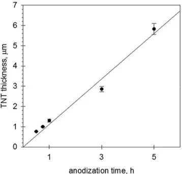
Moreover, particular attention was given to the evaluation of the efficiency of the PEC cell. To pursue this aim, titania nanotubes of different lengths (from 0.5 to 6 m) were synthesized by varying the anodization time from 30 min to 5 h. A monochromator and a spectroradiometer were used to evaluate the light irradiance at different wavelengths directly inside the PEC device. These measurements allowed for the calculation of different kinds of efficiencies: i) the photoconversion efficiency, also called solar-to-hydrogen efficiency (STH), which takes into account the amount of energy supplied in terms of light and the products obtained (i.e. hydrogen); ii) the Faradaic efficiency (η), which relates the photo-generated current to the produced hydrogen; iii) the quantum efficiency, expressed as IPCE (incident photon to current efficiency) and APCE (absorbed photon to current efficiency). The most important results (reported in detail in Chapter 3) showed that, for use in a PEC cell, the 45-min-anodized nanotube arrays (tube length of about 1 µm) provided the best performance, with a H2 production of 22.4 mol h-1 cm-2 and a STH efficiency as high as 2.5%. These values
are among the best ever reported insofar as undoped TiO2 photoanodes are used and in
absence of external bias or sacrificial agents. The final part of Chapter 3 was dedicated to the preparation of 3D-type meso/macro porous structured photoanodes based on Ti mesh, working as a hierarchical structure (consisting of Ti mesh macropores and TiO2 nanotube
mesopores) to improve the mass and charge transport within the PEC cell.
In order to improve the light absorption in the visible region, it is necessary to dope the
nanostructured TiO2 materials with heteroatoms or decorate their surface with metal
nanoparticles. In this direction, nanoparticles of gold (Au) were deposited on the surface of
TiO2 nanotubes by optimizing three different techniques (wet impregnation, photo-reduction
VII and a photo-electrochemical (PEC) cell, both homemade. Furthermore, with the aim of
exploiting earth-abundant and low-cost materials, photocatalysts based on Cu-doped TiO2
nanotubes were also synthesized and successfully tested in the PEC cell for H2 production in
water-photo-electrolysis and ethanol photo-reforming. This part of the work was carried out in collaboration with the Institute of Chemistry in Araraquara (Brazil). The CuO nanoparticles were deposited by adopting two different techniques, dip-coating and electrodeposition. The results (reported in detail in Chapter 4) showed that the presence of small metal (Au and Cu)
nanoparticles strongly increased H2 production rate in a gas photo-reactor, with a maximum
of about 190 mol in 5 h of light irradiation obtained for Au-doped TiO2 nanotubes prepared
by electrodeposition. However, in the PEC cell (with oxidation/reduction half reactions separated in two different chambers of the cell) it was observed that the presence of metal nanoparticles on TiO2 surface at the photo-anode can create a counter-circuited current,
diminishing the H2 production at the cathode side. However, this phenomenon was
successfully minimized by preparing very small CuO nanoparticles (lower than 2 nm)
decorating the internal walls of the TiO2 nanotubes by controlled dip-coating technique.
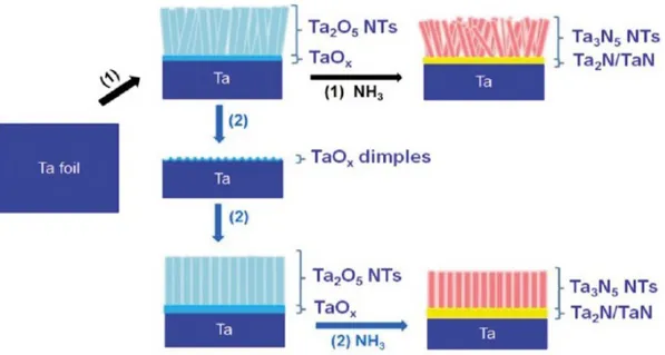
Finally, nanostructured tantalum oxynitride (Ta-oxy-N) electrodes were synthesized through controlled anodic oxidation technique, by adapting the synthesis conditions
previously optimized for TiO2. The advantages of these tantalum-based materials refer to their
lower band-gap (1.9-2.5 eV) with respect to titania (3.0-3.2 eV), thus improving light absorption in the visible region. After the anodization, a high temperature nitridation process
(600-900 °C) was needed to replace partially oxygen with nitrogen in the Ta2O5 lattice. The
results (reported in detail in Chapter 5) allowed to obtain a clear correlation between the parameters using during the synthesis (i.e. applied voltage, anodization time) and the Ta-oxy-N nanostructures (nanotube diameter and length, wall thickness and grade of voids). The best photocurrent response was obtained for the Ta-oxy-N sample anodized at 40 V for 1 min and then thermally treated with ammonia at 800°C. However, further investigation is needed to improve the mechanical resistance of these photo-catalysts.
VIII
Abstract (Italian)
La possibilità di sfruttare l'energia solare per la produzione diretta di combustibili e prodotti chimici (quali idrogeno, idrocarburi ed alcoli) rappresenta la sfida del prossimo futuro per muoversi verso una nuova economia verde, recentemente definita come "solar-driven chemistry".
In quest’ottica, la tesi di dottorato si concentra sullo sviluppo di un nuovo approccio per convertire l'energia solare, attraverso la sintesi di materiali ed elettrodi innovativi fotoattivi per la produzione di combustibili solari. Assemblando questi foto-elettrodi in una cella fotoelettrochimica (PEC), progettata apposta per imitare ciò che la natura fa con le foglie, l'energia solare può essere catturata e utilizzata per produrre idrogeno dall'acqua (mediante foto-elettrolisi) o per generare composti a base di carbonio ad alto valore aggiunto (attraverso la riduzione della CO2 atmosferica) in un processo a singolo stadio del tutto simile ad una
"foglia artificiale". Pertanto, l'obiettivo principale del presente lavoro di dottorato è stato quello di sviluppare film sottili fotocatalitici in grado di funzionare come fotoanodi in dispositivi PEC, ed in particolare per la produzione di idrogeno.
Le attività di dottorato sono state svolte presso il laboratorio CASPE/INSTM (Laboratory of Catalysis for Sustainable Production and Energy) dell'Università di Messina. Durante i tre anni di attività, sono stati attentamente valutati tutti gli aspetti riguardanti le prestazioni dei fotocatalizzatori, dei relativi elettrodi nonché delle celle PEC.
Inizialmente, l'attività di ricerca si è concentrata sulla preparazione di nanotubi di titanio (TiO2) sintetizzati mediante la tecnica dell’ossidazione anodica controllata. La particolarità di
questo metodo risiede nella possibilità di "personalizzare" la morfologia e la nanostruttura del catalizzatore modulando alcuni parametri durante la sintesi (come la composizione dell'elettrolita, il pH, la tensione applicata, il tempo di anodizzazione). In generale, l'uso del biossido di titanio come fotocatalizzatore, nonostante i suoi numerosi vantaggi (basso costo, non tossicità, resistenza alla foto-corrosione, elevata resa quantica) presenta due principali inconvenienti: i) il basso assorbimento di luce nella regione visibile, a causa dell’elevato band-gap (compreso tra 3.0 e 3.2 eV) e ii) l’elevata ricombinazione di carica, che di solito si verifica ai bordi dei grani delle particelle. Quest'ultima può essere mitigata con la realizzazione di
IX nanostrutture come nanotubi o nanorod, che possono migliorare il trasporto vettoriale degli elettroni verso lo strato collettore di Ti.
Diverse tecniche di caratterizzazione (SEM-EDX, TEM, XRD, Spettroscopia a Riflettanza Diffusa UV-visibile) sono state utilizzate per studiare le proprietà dei nanotubi di TiO2
sintetizzati, mentre per valutare il loro comportamento elettrochimico sono state effettuate delle misurazioni di voltammetria ciclica e crono-amperometria. Parte della caratterizzazione mediante microscopia elettronica è stata effettuata in collaborazione con il Dipartimento di Scienze Chimiche dell'Università di Padova. L'obiettivo principale è stato quello di ottenere una correlazione tra parametri di sintesi, proprietà della nanostruttura e prestazioni fotocatalitiche.
Inoltre, è stata prestata particolare attenzione alla valutazione dell'efficienza della cella PEC. Per raggiungere questo scopo, sono stati sintetizzati nanotubi di titania di diverse lunghezze (da 0,5 a 6 μm) variando il tempo di anodizzazione da 30 minuti a 5 ore. Un monocromatore e uno spettroradiometro sono stati usati per valutare l'irradianza della luce a diverse lunghezze d'onda direttamente all'interno del dispositivo PEC. Queste misurazioni hanno consentito il calcolo di diversi tipi di efficienza: i) l'efficienza di fotoconversione, detta anche efficienza solare a idrogeno (STH), che tiene conto della quantità di energia fornita in termini di luce e prodotti ottenuti (cioè idrogeno); ii) l'efficienza Faradica (η), che collega la corrente generata direttamente all'idrogeno prodotto; iii) l'efficienza quantica, espressa come IPCE (incident photon to current efficiency) e APCE (absorbed photon to current efficiency). I risultati più importanti (riportati in dettaglio nel Capitolo 3) hanno mostrato che, per l'utilizzo in una cella PEC, i nanotubi di TiO2 preparati con un tempo di anodizzazione di 45 min
(lunghezza del tubo di circa 1 μm) forniscono le migliori prestazioni, con una produzione di H2
di 22,4 µmol h-1 cm-2 e un’efficienza STH del 2,5%. Questi valori sono tra i migliori mai riportati
per una cella PEC in cui viene utilizzato TiO2 non drogato ed in assenza di potenziale esterno
e/o agenti sacrificali. La parte finale del capitolo 3 è stata dedicata alla preparazione di fotoanodi meso/macro strutturati (3D-type) basati su reti di Ti, che funzionano come una struttura gerarchica (costituita dai macropori della rete di Ti e dai mesopori dei nanotubi di TiO2) per migliorare il trasporto di massa all'interno della cella PEC.
X Per migliorare l'assorbimento della luce nella regione visibile, è necessario drogare i materiali nanostrutturati di TiO2 con eteroatomi oppure decorare la loro superficie con
nanoparticelle metalliche. Con questo intento, sulla superficie dei nanotubi di TiO2 sono state
depositate nanoparticelle d'oro (Au) ottimizzando tre diverse tecniche di deposizione (impregnazione ad umido, foto-riduzione ed elettrodeposizione) e le loro prestazioni sono state studiate utilizzando un reattore in fase gas (GP) e una cella fotoelettrochimica (PEC). Inoltre, allo scopo di limitare al massimo l’utilizzo di metalli nobili, sono stati realizzati dei fotocatalizzatori basati su nanotubi di TiO2 drogati con Cu, testati poi con successo nella cella
PEC per la produzione di H2 nei processi di foto-elettrolisi dell’acqua e foto-reforming
dell’etanolo. Questa parte del lavoro è stata svolta in collaborazione con l'Istituto di Chimica di Araraquara (Brasile). Le nanoparticelle di CuO sono state depositate adottando due diverse tecniche, il dip-coating e l'elettrodeposizione. I risultati (riportati in dettaglio nel capitolo 4) hanno dimostrato come la presenza di nanoparticelle di metallo (Au e Cu) aumenti
notevolmente la velocità di produzione di H2 nel foto-reattore in fase gas, con un massimo di
circa 190 µmol in 5 ore di irradiazione per i campioni di TiO2 drogati con Au preparati per
elettrodeposizione. Tuttavia, nella cella PEC (in cui le semi-reazioni di ossidazione e riduzione avvengono in due ambienti separati) è stato osservato che la presenza di nanoparticelle
metalliche sulla superficie di TiO2 diminuisce la produzione di idrogeno al catodo, poiché le
particelle metalliche agiscono da centri di riduzione direttamente nel comparto anodico con conseguente corto-circuito della corrente elettrica. Tuttavia, si è cercato di risolvere tale problematica preparando mediante la tecnica del dip-coating delle nanoparticelle di CuO
molto piccole (inferiori a 2 nm) localizzate preferenzialmente all’interno dei nanotubi di TiO2.
Infine, sono stati sintetizzati degli elettrodi nanostrutturati a base di ossido di tantalio (Ta-oxy-N) mediante la tecnica di ossidazione anodica controllata, adattando le condizioni di sintesi precedentemente ottimizzate per il TiO2. I vantaggi di questi materiali a base di tantalio
sono legati al loro band-gap (1,9-2,5 eV) inferiore rispetto alla titania (3,0-3,2 eV), migliorando così l'assorbimento della luce nella regione visibile. Dopo l'anodizzazione, è stato necessario un trattamento con ammoniaca ad alta temperatura (600-900 °C) per sostituire parzialmente l'ossigeno con l'azoto nel reticolo del Ta2O5. I risultati (riportati in dettaglio nel capitolo 5)
XI (cioè voltaggio applicato e tempo di anodizzazione) e le nanostruttura di Ta-oxy-N (diametro e lunghezza dei nanotubi, spessore della parete e grado di vuoto). La risposta migliore in termini di fotocorrente è stata ottenuta per il campione di Ta-oxy-N anodizzato a 40 V per 1 minuto e successivamente trattato termicamente con ammoniaca a 800 °C. Tuttavia, sono necessarie ulteriori indagini per migliorare la resistenza meccanica di questi catalizzatori.
1
1 Introduction
Energy consumption overview
In the last decade, the global primary energy consumption has grown at an average rate of 1.7% per year, despite the greatest world economic crisis since World War II. Particularly, primary energy consumption grew strongly in 2017 (by 2.2%), up from 1.2% last year and it is the fastest growth since 2013. All fuels, except coal and hydroelectricity, grew at above-average rates. Natural gas accounted for the largest increment in energy consumption at 83 million tonnes of oil equivalent (Mtoe), followed by renewable energy (69 Mtoe), which grew fast driven by robust growth in both wind and solar power, and finally oil (65 Mtoe) [1]. Oil and coal continues to represent the first energy source (Figure. 1.1), the largest majority of which (ca. 80%) is used to power the world transportation system, the remainder being used for heat and electricity, petrochemicals, asphalt and lubricants, in order of decreasing importance [1-2]. The most relevant change in the world energy landscape is the rise of renewable energies, primarily in the electricity sector. In 2014, for the first time, global carbon emissions associated with energy production remained stable despite continued economic growth. This can be attributable to the increasing penetration of renewable enhanced energy efficiency, particularly in the affluent world. The key player in this changing scenario is China, which now produces as much electricity from water, wind, and sunlight, as all France and Germany’s power plants combined [3]. The almost 7-fold drop of the photo-voltaic (PV) module price in the last decade has been the consequence of the 10-fold increase of the Chinese production; this has made PV a truly game changer in the global energy market. The number of countries where PV electricity is competitive with conventional technologies (e.g., coal or nuclear) is constantly increasing and its contribute of electricity production in some industrialized countries has become remarkable. In 2014, Italy produced almost 8% of its consumption by PV, now the largest share in the world [4]. All the renewable energy sectors continue to grow, the estimated renewable share of final energy consumption is about 19.3%, modern technologies and traditional biomass being at 10.2 and 9.1% respectively. By far, the most important renewable sector is electricity production, with 22.8% of the overall world’s generation. At the end of
2 2016, hydroelectric global capacity exceeded 1 TW, wind was 370 GW, and PV almost 180 GW; they covered 19.3, 3.1 and 0.9 %, respectively, of the world electricity demand. The above selected data suggest that the energy transition from fossil fuels to renewables is already ongoing [5].
Sunlight
Energy represents the most important resource for humanity and sunlight is our primary energy source. Sunlight is abundant (90 PW received on the earth’s surface), inexhaustible (the sun will last for more than 4 billion years), and fairly well distributed over the planet [6]. A very small fraction of solar energy, about 0.1% is converted and stored in terrestrial biomass by natural photosynthesis [7].
Solar energy, is not useful unless it is converted into heat, electricity, and fuels the final usable energy forms for mankind. Conversion of solar energy into heat is clear, but conversion of solar energy into electricity and fuels, the noblest energy forms, poses several problems [8].
First of all, conversion of sunlight into electricity and fuels can only be done by processes that limit the conversion efficiency. Since the solar spectrum cannot be modified, materials
3 capable of exploiting sunlight and converting efficiently photons in energy should be developed.
Taking into account the average spectral distribution of solar energy, the most favourable threshold is about 885 nm (1.4 eV), which in principle allows 33% energy conversion efficiency [9]. The materials suitable to be used for solar energy conversion should be: 1) cheap; 2) earth abundant, 3) low costly 4) with low environmental impact and 5) stable under prolonged exposure to sunlight irradiation. Solar energy unfortunately suffers by intermittency and intensity fluctuations due the atmospheric conditions and day/night cycles. For these reasons, the use of solar energy into electricity requires storage components to be integrated in the entire system. It is necessary to choose the best storage option to be compatible with the amount of energy stored [8].
Sunlight is dilute: the average solar power lighting the earth’s surface annually is about 170
W m-2. Only a small part of this power can be converted into fuel or electricity. Solar renewable
energies have average annual power densities ranging between 5–20 W m-2 (photovoltaic
panels) and <1 W m-2 (biomass). Power densities of final energy uses in modern societies range
between 10 and 70 W m-2 for houses and low-energy intensity manufacturing buildings.
Supermarkets and office buildings use 20–100 W m-2, energy intensive industrial activities such
as steel mills and refineries require 300–900 W/m2, whereas high-rise buildings may need up
to a few thousands W m-2 [10]. By considering these values, it is certainly possible to power a
house with the amount of sunlight intercepted by its roof, but this will never be possible for an oil refinery or a skyscraper.
Energy Return of Investment (EROI)
EROI (energy return on investment) is an important parameter to quantify energy costs. This index takes in account the quantity of gained energy divided by the energy required to get that energy (Equation 1.1) [11].
4 If the EROI is equal to or less than one, the energy is dissipated and its value as a primary energy source becomes not convenient. The calculation of EROI is extremely complex, because it involves the aggregation of different energy investments, which so far has made it difficult to formulate a universally accepted calculation methodology, but it is a useful parameter to compare the same energy sources [11].
In the case of oil, the EROI can be estimated from the ratio between the number of barrels extracted divided by the number of barrels consumed to carry out the extraction process. The EROI declined over time, as the availability of primary energy sources decreases with the depletion of the reservoir.
On the contrary, in the case of renewable energy the EROI increases over time due to technological improvements. For solar energy, EROI refers to the energy produced and invested in the conversion device (photovoltaic modules) [12]. The EROI, as defined by equation (1) is a good parameter for estimating the "energy balance point" of a fuel, for example, if there is a net gain or energy loss at the farm gate to produce ethanol from corn.
The energy of human labour as well as the quality of energy obtained with reference to its specific use and the energy needed to compensate for environmental impacts should be included for a more precise assessment of an energy source [13]. As discussed above, the average EROI of fossil fuels is decreasing due to the depletion of the deposits. For example, the EROI for oil in the United States declined from about 20 in 1970 to about 11 in 2013. In the same year, the EROI of oil production from ultra-deep areas was less than 10, while the EROI for the shale oil was estimated around 1.5 [14].
A concept related to EROI is that of “net energy”, defined as the difference between the
energy acquired from a given source (gross energy, Eout) and the energy used to obtain and
supply that energy (Ein), measured during the entire life cycle (Equation 1.2). Equation 1.1
allows us to express the net energy as a function of EROI (Equation. 1.3).
net energy = Eout – Ein (1.2)
net energy = Eout (1-1/EROI) (1.3)
From Equation (3) it can be seen that the relationship between net delivered energy and decreasing EROI is not linear. The net delivered energy, in the other hand, decrease as EROI
5 decreases. For example, 1 L of a fuel with an EROI of 100 delivers 99% of that fuel to society, whereas 1 L of a fuel with an EROI of 2 delivers only 50% [15].
EROI should be one of the most important factors in determining the quality of life of any government. If the EROI declines, the net energy provided to society declines and, at some point, the amount of net energy will be insufficient to meet the existing demand. The EROI that provides just enough net energy to support all current energy needs represents the minimum EROI for a sustainable society, a value that is different for different societies [13].
Solar Fuels
The possibility to produce fuels or chemicals from water and CO2 by using solar energy
directly (by using a PEC device) or indirectly (with the electrical energy produced from photovoltaic) represents the challenge of the new century [16].
Production of solar fuels includes in his concept all the renewable energy sources (RE), and thus is not limited to the direct use of solar radiation. In the last decades, most studies have focused on the production of H2 by water splitting, but a growing interest concerns the
conversion of CO2. RE suffers the problem related to fluctuations in the production and
long-range transport of electrical energy, while the production of solar fuels, allowing the storage and distribution of RE, may be the key element to switch from a centralized energy production model to a new energy model based on distributed energy production and storage [17].
In nature, the classic example of solar fuels production is given by chlorophyll photosynthesis, which converts light into chemical energy that can later be released as "fuel for life activities". The time taken by plants to produce fuel is not sufficient to satisfy the energetic demand of human activities, so the need arises to develop artificial systems (artificial leaves, (see paragraph 1.7) that imitate the process of photosynthesis but at the same time satisfy the chemical industry's requirements. An artificial leaf must guarantee a continuous production (under sunlight) and possess a solid and resistant structure. In the next paragraphs both natural and artificial photosynthesis will be described.
6
Natural Photosynthesis
The photosynthesis is the process responsible for life on earth, using sunlight to convert CO2
and H2O into carbohydrates (sugar). The process of photosynthesis is initiated by the capture
of sunlight by a network of light-absorbing molecules (chromophores), which are also responsible for the subsequent funnelling of the excitation energy to the reaction centres. Through evolution, genetic drift, and speciation, photosynthetic organisms have discovered many solutions for light harvesting. There are a large variety of different types of light-harvesting complexes found in nature [18]. Different light-light-harvesting complexes have evolved to allow efficient absorption of the wavelengths of the solar spectrum that are available to photosynthetic species in any particular ecological sector. Higher plants, that are exposed to the full solar spectrum available at the surface of the earth, possess chlorophyll as the main light-harvesting pigment. The structures of the different types of light-harvesting pigment protein complexes reflect the necessary structural requirements to collect the different types of wavelength. These polypeptides collocate perfectly the pigments with respect to the distances between them and the relative orientation of the transitions dipole moments of the pigments’ excited states that are involved in the energy transfer reactions [19]. The three stages of photosynthesis take place in the presence of light: (1) light harvesting from sunlight; (2) use of that energy for the production of ATP and reducing power, reduced ferredoxin, and
NADPH; and (3) capture and conversion of CO2 into carbohydrates and other cell constituents
[20]. During the third stage, namely, the carbon reactions, long incorrectly designated as the “light independent reactions”, the energy-rich products of the light reactions are used to
reduce CO2. The heart of the photosynthetic process is the splitting of water by sunlight into
oxygen and hydrogen. The oxygen is released into the atmosphere where it is available for living beings to breathe and for burning fuels. The hydrogen is combined with carbon dioxide to make sugars and other organic molecules of various types. When fuels burn (fossil, biomass and other biofuels) the hydrogen stored in these organic molecules combines with oxygen, completing a cycle started millions of years ago. From the energetic point of view, the synthesis of organic molecules represents a way of storing hydrogen and therefore storing solar energy in the form of chemical bonds (figure. 1.2) [21].
7
Figure 1.2: Simplified photosynthesis cycle reproduced with permission from ref. [21].
Figure 1.3 shows a simplified Z-scheme of the light reactions of photosynthesis [22]. For
every electron extracted from water and transferred to CO2, the energy of two photons of light
is required. One is absorbed by Photosystem II (PSII), which generates a strong oxidising species (P680+), able to drive the water splitting reaction and a reduction of pheophytin (Pheo) and then plastoquinol (Q) to plastoquinol (QH2). The other, Photosystem I (PSI), generates a strong
reducing species, NADPH, which donates reducing equivalents to CO2 to produce sugars and
other organic molecules, and a weak oxidant P700+. Electron and proton flow from QH2 to P700+ is aided by the cytochrome b6f (Cyt b6f) complex and plastocyanin (PC) and results in the release of energy to convert ADP to ATP. The ATP produced is required, along with NADPH, to convert CO2 to sugars. Since the production of O2 requires the splitting of two water
molecules, the overall process involves the removal of two electrons per water and therefore four photons per PSII and PSI reaction centre. The reduction of oxidised nicotinamide adenine dinucleotide phosphate (NADP+) by PSI is facilitated by membrane bound iron sulphur proteins (Fx, FA and FB) and soluble ferredoxin (FD).
Quantum yield efficiency of the plants is very low (below 1%) and only some microalgae achieve slightly better efficiencies [23]. Improving light harvesting and conversion processes, and modifying the process to produce directly the target solar fuels, are the two main aspects to move to the realization of the artificial leaves, but which need to be sufficient simple and robust to be competitive with plants.
8
Figure 1.3: Simplified Z-scheme of the light reaction of photosynthesis.
Artificial Photosynthesis
The most important photochemical processes are the splitting of water to oxygen and hydrogen. Photosynthesis produces the energy that sustains life on our planet by using solar light to rearrange the bonds of water to oxygen and hydrogen; the hydrogen is fixed by its combination with carbon dioxide to produce carbohydrate. Analysis of the energetics of the solar fuels conversion process shows that it is water splitting and not carbohydrate production that is at the heart of solar energy storage [21]. The possibility to achieve the production of fuels by artificial photochemical reactions were first predicted by the Italian chemist Giacomo Ciamician over one century ago [24]. The studies on artificial photosynthesis are currently concentrated on using sunlight to reduce carbon dioxide in aqueous solution to carbon monoxide, ethanol, or methane (equation 1.4) [25] or to split water into molecular hydrogen and molecular oxygen (equation 1.5). Since carbon dioxide reduction is more difficult than water splitting from a kinetic point of view and can also be performed by a thermal reaction with molecular hydrogen to yield methanol [26], the attention of most scientists is focused on the water splitting (WS) reaction (equation 1.5):
𝐶𝑂 + 2 𝐻 𝑂 + 8 ℎ𝑣 → 𝐶𝐻 + 2 𝑂 ∆𝐺 = 8.30 𝑒𝑉 (1.4)
2 𝐻 𝑂 + 4 ℎ𝑣 → 2 𝐻 + 𝑂 2 ∆𝐺 = 4.92 𝑒𝑉 (1.5)
From the thermodynamic point of view, the most convenient water-splitting process concerns the evolution of molecular oxygen and molecular hydrogen from liquid water
9 (Equation 1.6), the low-energy thermodynamic barrier (1.23 eV) of which allows, in principle, conversion of about 30% of the solar energy. Water splitting entails two multi-electron-transfer reactions (Equations 1.7 and 1.8).
2 𝐻 𝑂 → 2𝐻 + 𝑂 ∆𝐺 = 1.23 𝑒𝑉 (1.6)
2 𝐻 𝑂 + 2𝑒 → 𝐻 + 2 𝑂𝐻 𝐸 (𝑝𝐻 7) = −0.41 𝑉 𝑣𝑠 𝑁𝐻𝐸 (1.7)
2 𝐻 𝑂 → 𝑂 + 4𝐻 + 4𝑒 𝐸 (𝑝𝐻 7) = +0.82 𝑉 𝑣𝑠 𝑁𝐻𝐸 (1.8)
Given that in a photochemical process each photon can transfer only one electron, [27] in a water-splitting system two catalysts must be present: one to collect electrons for the production of molecular hydrogen, the other one to collect holes (positive charges) for the generation of molecular oxygen [28]. The design of efficient, cost-effective artificial systems requires to maintain the main elements in the leaf-like hierarchical structures of natural leaves, but developing new functional elements inspired from the key steps of natural photosynthesis. An artificial leaf should be composed of the following main elements:
a) an anode, exposed to sunlight carrying a photocatalyst able to oxidize water, and supported on a conductive substrate which allows the fast collection of the electrons, but at the same time is permeable to protons, in order to transport the electrons and protons to the cathode side. An alternative approach is to prepare 2D photonic materials adsorbing in the visible and use sensitizers for a two-photon transfer process of energy to the semiconductor
b) a membrane enabling fast transport of protons (possibly also electrons, but which preferably have to be transported externally through a wire or through physically separated elements of the membrane to avoid their recombination). Possibilities are carbon nanotubes
or TiO2 connecting the two electrodes and ion-exchange resins, like Nafion® or other
proton-conducting polymeric membranes. The membrane should be tailored to provide the minimum transfer resistance to protons and have also a minimum thickness (in principle some microns), but also at the same time block oxygen permeation to preserve hydrogen synthesis activity at the cathode. The membrane should be also in good contact with the anode and cathode sites and it is necessary to minimize the resistances at the interface [29].
10 c) a cathode, formed by a conductive substrate (in contact with the membrane and
permeable to protons) containing active centres for proton and electron recombination to H2.
Whit a different approach, a specific cathode can possess centres able to convert catalytically the CO2 to solar fuels [30-31]. Developing an artificial leaf that collects energy in the same way
as a natural one, is potentially the solution solving the problems of sustainability of energy. To
avoid intermittency of solar energy, it is necessary to design systems which directly capture CO2
and convert it into liquid solar fuels which can be easy stored. H2 production can be seen as a
necessary, but intermediate step, due to the storage difficulties of this gas. However, to be advantageous over natural leaves, it is necessary that artificial leaves have a higher solar-to-chemical conversion efficiency, provide directly the fuels which can be then used in power-generating devices, and finally be robust and of easy construction [22].
The Artificial Leaf
As discussed above, the natural leaf converts the energy of sunlight into chemical energy and splits water via the photosynthetic process to produce molecular oxygen and hydrogen, which is in a form of separated protons and electrons.
To overcome the issues of natural photosynthesis, the realization of an artificial leaf requires:
- the use of earth abundant materials, - a good production rate,
- a good efficiency and robustness of the materials under prolonged UV-visible light.
Focusing on these statements, Nocera et al. reported the concept of “artificial leaf” by realizing a triple junction, amorphous silicon photovoltaic with hydrogen- and oxygen-evolving catalysts made from a ternary alloy (NiMoZn) and a cobalt phosphate cluster (Co-OEC) [32].
The first attempt made by Nocera involved the realization of a single junction Si cell (npp+), a
metal contact deposited in the n side and a ITO layer on the p side to protect the silicon from the electrolyte corrosion. The Co-OEC (oxygen evolution catalyst) was electrodeposited on ITO barrier to improve oxygen evolution (figure 1.4a).
11 Figure 1.4b show the schematic composition of the triple-junction artificial leaf made by Nocera et al.: Co-OEC and NiMoZn are interfaced with a triple junction amorphous Si (3jn-a-Si)
solar cell. The 3jn-a-Si produced 8 mA cm2 of current at 1.8 V at an overall efficiency of 6.2%.
Like the single junction cell, the p-side of the cell was protected with an ITO layer. The NiMoZn was used ad HEC (hydrogen evolution catalyst) and electrodeposited onto the stainless steel support of the 3jn-a-Si cell. The NiMoZn HEC alloy may be deposited directly onto Si, to act as protection layer. When the wireless CoPi|3jn-a-Si|NiMoZn wafer was immersed in an open
container of electrolyte and illuminated with sunlight, O2 bubbles evolved from the anode at
the front face and bubbles of H2 evolved from the cathode at the back of the wireless cell,
providing an efficiency of 2.5%.
A B
Figure 1.4: a) Schematic of a Co-OEC functionalized npp+-silicon single- junctionPECcel and b) scheme of triple
junction-a-Si solar cell made by Nocera. Reproduced with permission from ref. [32].
The cell exposed by Nocera has started numerous research activities in the field of photo-electrochemical production of fuels. The different types of photo-photo-electrochemical cell (PEC) will be discussed in the next chapter.
12
References
[1] BP Statistical Review of World Energy 2018, https://www.bp.com/, accessed 15 September (2018)
[2] P.N.R. Vennestrøm, C.M. Osmundsen, C.H. Christensen, E. Taarning, Beyond Petrochemicals: The Renewable Chemicals Industry, Angew. Chem. Int. Ed., 50, 10502– 10509 (2011)
[3] J. A. Mathews, Greening of Capitalism, How Asia Is Driving the Next Great Transformation, Stanford University Press, Stanford (USA) (2015)
[4] http://www.enea.it/it/Ricerca_sviluppo/lenergia/fonti-rinnovabili, accessed 15
September (2018)
[5] REN 21—Renewable Energy Policy Network for the 21st Century, Annual report 2017, http://www.ren21.net/, accessed 15 September (2018)
[6] D. Abbott, Keeping the Energy Debate Clean: How Do We Supply the World’s Energy Needs? Proc. IEEE, 98, 42−66 (2010)
[7] R.J. Cogdella, A.T. Gardinera, N. Yukihirab, H. Hashimotob, Solar fuels and inspiration from photosynthesis, J. of Photochem. and Photobiol. A: Chem., 353, 645–653 (2018)
[8] N. Armaroli, V. Balzani, Energy for a Sustainable World—From the Oil Age to a Sun Powered Future, Wiley-VCH, Weinheim (Germany), (2011)
[9] G. Porter, Criteria for Solar Energy Conversion, in Light, Chemical Change and Life, A Source Book in Photochemistry, Open University Press, Milton Keynes (UK), 338–345 (1982)
[10] V. Smil, Energy Transitions: History, Requirements, Prospects, Praeger/ABC-CLIO, Santa Barbara, CA (USA), (2010)
[11] D.J. Murphy, C.A.S. Hall, Year in review—EROI or energy return on (energy) invested, Ann. N. Y. Acad. Sci., 1185, 102–118, (2010)
[12] F. Ferronia, A. Guekosb, R.J. Hopkirkc, Further considerations to: Energy Return on Energy Invested (ERoEI) for photovoltaic solar systems in regions of moderate insolation, Energy Policy 107, 498–505 (2017)
[13] J.G. Lambert, C.A.S. Hall, S. Balogh, A. Gupta, M. Arnold, Energy, EROI and quality of life, Energy Policy 64 153-167(2014)
[14] N. Armaroli, V. Balzani, Solar Electricity and Solar Fuels: Status and Perspectives in the Context of the Energy Transition, Chem. an Eur. Jour., 22, 32–57 (2016)
[15] DJ Murphy, The implications of the declining energy return on investment of oil production, Phil. Trans. R. Soc. A 372 20120320 (2014)
[16] M. Beller, G. Centi, L. Sun, Chemistry Future: Priorities and Opportunities from the Sustainability Perspective, ChemSusChem, 10, 6–13 (2017)
13 [17] P. Lanzafame, S. Abate, C. Ampelli, C. Genovese, R. Passalacqua, G. Centi, S. Perathoner, Beyond Solar Fuels: Renewable Energy-Driven Chemistry, ChemSusChem, 10, 1–12 (2017) [18] T. Mirkovic, E.E. Ostroumov, J.M. Anna, R. van Grondelle, Govindjee, G.D. Scholes, Light absorption and energy transfer in the antenna complexes of photosynthetic organisms, Chem. Rev. 117, 249–293 (2017)
[19] R.J. Cogdell, A. Gall, J. Kohler, The architecture and function of the light-harvesting apparatus of purple bacteria: from single molecules to in vivo membranes, Q. Rev. Biophys. 39, 227–324 (2006)
[20] Govindjee; R. Govindjee, Primary Events in Photosynthesis, Sci. Am., 231 ,68–82 (1974) [21] J. Barber, Photosynthetic Energy Conversion: Natural and Artificial, Chem. Soc. Rev., 38,
185–196 (2009)
[22] S. Bensaid G. Centi E. Garrone S. Perathoner G. Saracco Towards Artificial Leaves for Solar Hydrogen and Fuels from Carbon Dioxide, ChemSusChem 5-3 500-521 (2012)
[23] T.H.P. Brotosudarmo, M.N.U. Prihastyanti, A.T. Gardiner, A.M. Carey, R.J. Cogdell, The Light Reactions of Photosynthesis as a Paradigm for Solar Fuel Production, Energy Procedia 47 283–289 (2014)
[24] G. Ciamician, The Photochemistry of the Future, Science, 36, 385–394 (1912)
[25] C.D. Windle, R.N. Perutz, Advances in molecular photocatalytic and electrocatalytic CO reduction, Coord. Chem. Rev., 256, 2562–2570 (2012)
[26] G.A. Olah, Towards Oil Independence Through Renewable Methanol Chemistry, Angew Chem. Int. Ed., 52, 104–107 (2013)
[27] V. Balzani, P. Ceroni, G. Bergamini, Light: A Very Peculiar Reactant and Product, Angew. Chem. Int. Ed, 54, 11320–11337, (2015)
[28] A. Sartorel, M. Bonchio, S. Campagna, F. Scandola, Tetrametallic molecular catalysts for photochemical water oxidation, Chem. Soc. Rev., 42, 2262–2280 (2013)
[29] S. Bensaid, G. Saracco, Advanced membrane science and technology for sustainable energy and environmental applications, Series in Energy No. 25, Woodhead Pub. Lmd, Cambridge, UK, pp. 610-644 (2011)
[30] G. Centi, S. Perathoner, R. Passalacqua, C. Ampelli, Carbon-Neutral Fuels and Energy Carriers, CRC Press (Taylor & Francis Group), Boca Raton, FL (US), pp. 291–323 (2011) [31] G. Centi, R. Passalacqua, S. Perathoner, D. S. Su, G. Weinberg, R. Schloegl, Oxide thin films
based on ordered arrays of 1D nanostructure. A possible approach toward bridging material gap in catalysis, Phys. Chem. Chem. Phys, 9, 4930-4938 (2007)
14
2 Materials & Reactors
Titanium Dioxide (TiO
2): overview
During the last decades, scientific studies on photocatalysis have been grown at enormous rate, since the discover of photocatalytic water splitting on a semiconductor by Fujishima and Honda [1].
Titanium dioxide (TiO2), which is one of the most basic materials in our daily life, has been
widely studied and numerous scientific papers can be found in literature [2]. Fujishima et al. firstly demonstrated the possibility to conduct solar photo-electrolysis by using n-type TiO2
semiconductor electrode, which was connected through an electrical load to a platinum black counter electrode and exposed to near-UV light (Figure 2.1) [2].
Figure 2.1: Schematic representation of photoelectrochemical water electrolysis using an illuminated oxide semiconductor electrode. Reproduced with permission from ref. [3].
When light of wavelengths in the UV region (shorter than ∼415 nm) hit the surface of the
TiO2 electrode, photocurrent flowed through the external circuit from the platinum counter
electrode to the TiO2 electrode. The oxidation reaction (oxygen evolution) occurred at the TiO2
15 [3] demonstrated that water can be decomposed into oxygen and hydrogen, without the application of an external voltage under UV-visible light, according to the following scheme:
TiO2 + 2hv → 2e− + 2H+ (2.1)
at the TiO2 electrode
H2O+ 2h+ → (1/2)O2 + 2H+ (2.2)
at the Pt electrode
2H+ + 2e− → H2 (2.3)
the overall reaction is
H2O+ 2hv → (1/2)O2 +H2 (2.4)
Thermodynamic equilibration takes place at the interface of the semiconductor electrode, when this is in contact with an electrolyte solution. This may result in the formation of a space-charge layer within a thin surface region of the semiconductor. In the cases of n- and p-type semiconductors, the electronic energy bands are generally bent upwards or downwards, respectively. When the electrode receives photons with energies greater than that of the material’s band gap (BG), electron-hole pairs are generated and separated in the space charge layer. For an n-type semiconductor, the electric field existing across the space charge layer drives the photo-generated holes towards the interfacial region and the electrons towards the interior the electrical connection to the external circuit, while for a p-type semiconductor the reverse process takes place. [4-5] If the conduction band energy (CBE) is higher than the hydrogen evolution potential, photo-generated electrons can flow through the electrical wire to the counter electrode and reduce protons. Hydrogen gas evolution can be observed in the cathode side without an applied potential.
Figure 2.2 shows the band gap energy of the mostly studied semiconductors for water splitting. It is desirable that the band gap of the semiconductor is near that for optimum utilization of solar energy. When the semiconductor electrodes are used as photoanodes or photocathodes for water electrolysis, the bandgap should be at least 1.23 eV (under standard conditions), particularly considering the existence of overpotential and polarization losses due to, for example, oxygen evolution [6].
16
Figure 2.2: Bandgap of the most common studied semiconductor. Reproduced with permission from ref. [6].
Even if TiO2 has been the most studied semiconductor for water splitting, it mainly shows
two problems: 1) the wide energy band gap (3.0-3.2 eV) allowing it to capture light mainly in the UV region; 2) the high charge recombination rate, not allowing to convert efficiently solar
energy into chemicals (i.e. H2). Both these issues will be discussed in the next chapters through
the analysis of the experimental results.
Titanium Dioxide: anatase, rutile and brookite
In nature, there are three well-known crystal structure of TiO2: tetragonal rutile, tetragonal
anatase, and orthorhombic brookite, as shown in figure 2.4. All of them consist of TiO6
octahedrals, but differ in the distortion of the octahedron units and in the manners of sharing edges and corners. Anatase crystalline is a distorted octahedral coordination, in which every titanium atom is surrounded by six oxygen atoms in an elongated octahedral geometry, adopting axial symmetry. In rutile, additional in-plane (equatorial) and out-of-plane (axial) bond length and bond angle distortions exist, while in brookite, stronger distortions lead to a local symmetry loss and formation of symmetric TiO6 units. The difference in crystal structure
affecting their charge transfer characteristic and band energy levels [7]. For PEC applications rutile and anatase phase are the most studied because the rutile is the most thermodynamically stable form while anatase, whit higher charge mobility results more active for PEC application [8].
17
Figure 2.4: Crystal structures of TiO2 reproduced with permission from ref. [7].
Titanium dioxide: structure engineering
TiO2 photocatalysts can be prepared in many different shapes, both at micro and
nano-scales, by using advanced technological synthetic procedures. This has opened the route to many possibilities for materials engineering, which can produce the TiO2 materials in the
appropriate nanostructure and morphology in order to obtain the best performances depending on their application.
In general, there are many factors that can significantly influence photocatalytic performances (size, specific surface area, pore volume, pore structure, crystalline phase and exposed surface facets). One of the main aims in photocatalysis is to find the proper synthesis conditions in order to “tailor” the structure of the semiconductor (TiO2 in this case) and finally
relate these conditions to the photocatalytic activity.
According to their structure dimensionality and geometry, TiO2 materials can be divided in
different categories, starting to classic spheres that are considered as zero dimensional (0D), and moving to one dimensional rods and tubes (1D), two dimensional sheets (2D) and interconnected three dimensional architectures (3D) (see Figure 2.3) [9].
18
Figure 2.3: Schematic illustration of structural dimensionality of materials with expected properties, reproduced with permission from ref. [9].
2.3.1
Zero dimensional (0D): spheres
Nano- or micro-structured TiO2 spheres are the most widely studied and used in TiO2
-photocatalysis. TiO2 spheres usually possess a high specific surface area and a high pore volume
and pore size, with these properties increasing the size of the accessible surface area and the
rate of mass transfer for organic pollutant adsorption [10]. TiO2 nanoparticles are the common
element to realize nano films in dye-sensitized solar cells; Grätzel and co-workers have made great contribution to dye-sensitized TiO2 solar cells by studying the effects of nanoparticle size,
morphologies and film thickness [11]. These porous structures increase the light-harvesting
capabilities of TiO2 because they enhance light use by allowing the light to access the interior
of the particle [12-13]. TiO2 spheres are typically prepared from a titanium alkoxide such as
titanium tetraisopropoxide or titanium tetrabutoxide, in the presence of a polymer to provide a porous structure and with or without the addition of an acid to accelerate the reaction [14].
Depending on the annealing temperature, TiO2 spheres can have different structures.
Annealing at high temperatures usually decreases the specific surface area of the TiO2 spheres,
which exhibit superior photocatalytic activities. For example, Zheng et al. prepared TiO2
19 activity in the decomposition of organic molecules, because of their high specific surface area and highly crystalline form [15]. Size control of the particle is another key element to enhance the photocatalytic activity [16].
2.3.2
One dimensional (1D): fibers & tubes
TiO2 materials with one-dimensional structures includes fibers and tubes, possess higher
surface-to-volume ratio enabling a strong reduction of the hole–electron recombination rate and a high interfacial charge carrier transfer rate. With these unique properties, 1D TiO2
materials represent the perfect choice for photocatalytic reactions [17]. The one-dimensional architecture allows to obtain self-standing membranes; nonwoven mats can be obtained only
from this kind of architecture, which opens to a wide range of applications. TiO2 fibers have
already been used in an extensive range of applications, including photocatalysis, gas sensing [18], dye-sensitized solar cells (DSSCs) [19] and batteries [20]. The common synthesis to
prepare TiO2 fibers are the electrospinning of a mixture of titanium alkoxide and a polymer,
with a necessary calcination step to remove the residual polymer and crystallize the TiO2 (see
Figure 2.5) [21].
By changing the synthesis parameters (such as the ratio polymer/titanium alcoxide, the power of the electric field, and the feeding rate of the precursor in the electrospinning process),
the average diameter of the TiO2 fibers can be controlled. TiO2 fibers generally prepared by
electrospun generally possess a large surface area-to-volume ratios and provide efficient photocatalytic performances [22].
20
Figure 2.5: Schematic illustration of the setup for electrospinning. Reproduced with permission from ref. [9].
Nanotubes are of great interest due to their high surface-to-volume ratios and size
dependent properties: Compared to nanowires, TiO2 nanotubes have much been investigated
and various techniques have been developed for their synthesis. Titania nanotubes and nanotube arrays have been produced by a variety of methods including deposition into a nanoporous alumina template [23], sol–gel [24-25], and hydrothermal processes [26]. However, among these nanotube fabrication routes, anodization technique is the most
powerful tool for the fabrication of highly ordered TiO2 nanotube arrays [27-28].
Anodization is typically conducted in an electrolyte containing a hydrogen fluoride (HF)-based aqueous solution, using a two-electrode electrochemical cell with a platinum as counter electrode (cathode) at a constant potential. Figure 2.6 reports a schematic diagram of the electrochemical apparatus needed to carry out the anodization process. At the end of the
anodization process, TiO2 nanotube arrays are formed on the foil surface and have straight
21 of titania nanotube arrays via anodic oxidation of titanium foil in a fluoride-based solution was first reported in 2001 by Grimes and co-workers [29] followed by further studies focused on precise control and extension of the nanotube morphology: [30], length and pore size, and wall thickness [31]. Every single parameters of the synthesis determine the morphologies of the tubes. The electrolyte composition and pH determine the rate of nanotube array formation, as well as the rate at which the resultant oxide is dissolved [32]. In all cases, a fluoride ion
containing electrolyte is needed for nanotube array formation. Ordered TiO2 helical nanocoil
arrays can also be synthetized using 0.5 wt.% HF electrolyte [33].
Magnetic agitation is necessary during anodization experiments to reduces the thickness of the double layer at the metal/electrolyte interface, and ensures uniform local current density and temperature over the Ti electrode surface.
Figure 2.6: Illustrative drawing of a two-electrode electrochemical cell in which the Ti samples are anodized.
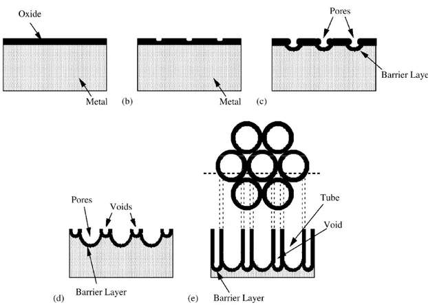
The key processes for the anodic formation of titania nanotube are: (1) Oxide growth at the surface of the metal occurs due to interaction of the metal with O2 or OH- ions. After the
formation of an initial oxide layer, these anions pass through the oxide layer and reach the
metal/oxide interface where they react with the metal. (2) Metal ion (Ti4+) migrate from the
metal to the metal/oxide interface; Ti4+ cations are removed from the metal/oxide interface
under application of an electric field, moving towards the oxide/electrolyte interface. (3) Field assisted dissolution of the oxide at the oxide/electrolyte interface. Due to the applied electric field, the Ti–O bond undergoes polarization and is weakened promoting dissolution of the metal cations. Ti4+ cations dissolve into the electrolyte, and the free O2 anions migrate towards
22 the metal/oxide interface - see process (1) - to interact with the metal. (4) Chemical dissolution of the metal, or oxide, by the acidic electrolyte also takes place during anodization. Chemical dissolution of titania in the HF electrolyte plays a key role in the formation of nanotubes rather than a nanoporous structure. The overall reactions for anodic oxidation of titanium can be represented as:
2H2O O2 + 4e- + 4H+ (2.5)
Ti + O2 TiO2 (2.6)
In the initial stages of the anodization process, field-assisted dissolution dominates chemical dissolution due to the relatively large electric field across the thin oxide layer. Small pits formed due to the localized dissolution of the oxide, represented by the following reaction, act as pore forming centers (Figure 2.7 a-b):
TiO2 + 6F- + 4H+ TiF62- + 2H2O (2.7)
Then, these pits convert into bigger pores and their density increases. After that, the pores spread uniformly over the surface. The pore growth occurs due to the inward movement of the
oxide layer at the pore bottom (Figure 2.7 c-d). The Ti4+ ions, migrating from the metal to the
oxide/electrolyte interface, dissolve in the HF electrolyte. The rate of oxide growth at the metal / oxide interface and the rate of oxide dissolution at the pore-bottom / electrolyte interface ultimately become equal; thereafter the thickness of the barrier layer remains unchanged although it moves further into the metal making the pore deeper (Figure 2.7c).
The anodization potential (as the concentration of electrolytes electrochemical) operates on the etch rate: if the electrochemical etch proceeds faster than the chemical dissolution the thickness of the barrier layer increases, which in turn reduces the electrochemical etching process to the rate determined by chemical dissolution. The chemical dissolution rate is
23
Figure 2.7: Schematic diagram of the evolution of a nanotube array at constant anodization voltage: (a) oxide layer formation, (b) pit formation on the oxide layer, (c) growth of the pit into scallop shaped pores, (d) metallic part between the pores undergoes oxidation and field assisted dissolution, and (e) fully developed nanotube array with a corresponding
top view. Reproduced with permission from ref. [34].
Chemical dissolution increases with increasing F- and H+ concentrations. Growth of
nanotube arrays can be achieved only in a certain F concentration range (from 0.05 to 0.3 mol/L in acidic solution).
2.3.3
Two dimensional (2D): nanosheets
Like the above discussed 1D structures, the 2D structures possess the advantage of a direct electron pathway but they have a higher specific surface area. A nanosheet is a flake-shaped material with a flat surface and high aspect ratio. Nanosheets can be prepared whit very small thickness of 1–10 nm and a lateral size can reach several tens of micrometers. This kind of shape results in low turbidity, excellent adhesion to substrates, and high smoothness, suitable for photocatalytic application. [35] Nanosheets present also superhydrophilicity under UV irradiation, a characteristic needed for self-cleaning coating. [36]. TiO2 nanosheets are typically
24 prepared according to an alkaline hydrothermal process using TiO2 powder as a precursor,
followed by either a calcination process or hydro/solvothermal reactions [37].
2.3.4
Three dimensional (3D): interconnected architecture
The three-dimensional hierarchical structures of TiO2 are important for practical
applications because possess an intricate pore structure and large surface to-volume ratios, this provides a significant advantage in diffusion pathways for guest species, such as organic pollutants opening the possibilities to conduct efficient purification, separation, and storage. The interconnected structure is potentially superior not only for carrier mobility, but also from
a practical point of view. For example, Konishi et al. prepared macroporous TiO2 monoliths for
use in chromatographic applications (Figure 2.7) [38], while Saravanan et al prepared mesoporous TiO2 for Li storage [39].
Figure 2.7: SEM image of TiO2 sponge. Reproduced with permission from ref. [38].
Titanium dioxide: strategies to improve performances
Various strategies can be adopted for improving the photocatalytic efficiency of TiO2. They
can be summarized as either morphological modifications, such as increasing surface area and
porosity, or as chemical modifications, by incorporation of additional components in the TiO2
25
2.4.1
Metal particle deposition
Modifications of TiO2 with transition metals such as Cr, Co, V and Fe have extended the
spectral response of TiO2 well into the visible region also improving photocatalytic activity [40]
[41] However, transition metals may also act as recombination sites for the photo induced charge carriers thus, lowering the quantum efficiency. Transition metals have also been found
to cause thermal instability to the anatase phase of TiO2. Kang argued that despite a decrease
in band gap energy has been achieved by many groups through metal doping, photocatalytic activity has not been remarkably enhanced because the metals introduced were not
incorporated into the TiO2 framework. In addition, metals remaining on the TiO2 surface block
reaction sites [42].
TiO2 has been modified with many transition metals such as Fe, Cu, Co, Ni, Cr, V, Mn, Mo,
Nb, W, Ru, Pt and Au [43-44] The incorporation of transition metals in the titania crystal lattice may result in the formation of new energy levels between valence band (VB) and conduction band (CB), inducing a shift of light absorption towards the visible light region. Photocatalytic activity usually depends on the nature and the amount of doping agent. Possible limitations are photocorrosion and promoted charge recombination at metal sites [45]. Deposition of noble
metals like Ag, Au and Pd on the surface of TiO2 enhances the photocatalytic efficiency under
visible light by acting as an electron trap, promoting interfacial charge transfer and therefore delaying recombination of the electron–hole pair [46-47-48]. The visible light responsiveness of TiO2 was accredited to the localized surface plasmon resonance (LSPR) of few metals
nanoparticles such as Au, Ag and Cu (Figure 2.8). LSPR is an optical phenomenon that appears when the wavelength of the incident light is higher than the metal NP size.
26
2.4.2
Metal free methods
In order to enhance the solar efficiency of TiO2 under solar irradiation, it is necessary to
modify the nanomaterial to improve visible light absorption. Non-metal doping of TiO2 has
shown great promise in achieving visible light absorber photocatalysis, with nitrogen being the
most promising dopant because nitrogen can be easily introduced in the TiO2 structure.
[50-51]. Nitrogen has a comparable atomic size with oxygen, small ionization energy and high
stability. Asahi and co-workers explored for first time the visible light activity of N-doped TiO2
produced by sputter deposition of TiO2 under a N2/Ar atmosphere, followed by annealing under
N2 [52]. There are many methods to introduce N in TiO2 materials, either in the bulk or as a
surface dopant. For the efficient incorporation of nitrogen into TiO2, several methods have
been adopted: physical techniques such as sputtering [53] and ion implantation [54], gas phase reaction methods [55], atomic layer deposition [56] and pulsed laser deposition [57].
Fluorine doping does not shift the TiO2 band gap; however, it improves the surface acidity
and causes formation of reduced Ti3+ ions due to the charge compensation between F− and Ti4+.
Thus, charge separation is promoted and the efficiency of photo-induced processes is improved [58].
Adding carbon, phosphorous and sulphur as dopants improves the light activity of TiO2.
These dopants change the lattice parameters, and the presence of trap states within the conduction and valence bands, gives rise to band gap narrowing. The effect is to improve visible light absorption and increase the lifetime of photo-generated charge carriers. [59] Carbon graphene oxide quantum dots (GOQD) were successfully added in-situ, during the anodization,
resulting in C doped TiO2 with an increased conductivity and photocatalytic activity [60].
Insertion of sulphur into the TiO2 lattice is more difficult to obtain, due to its larger ionic
radius. Insertion of cationic sulphur (S6+) is chemically favourable over the ionic form (S2−)
lattice. Visible light-activated sulphur doped TiO2 films were successfully synthesized using a
novel sol–gel method based on the self-assembly technique with a non-ionic surfactant to
control nanostructure and H2SO4 as an inorganic sulphur source [61]. S-doped TiO2 obtained
with H2S showed better performances in the methylene blue photodegradation test compared


![Figure 2.4: Crystal structures of TiO 2 reproduced with permission from ref. [7].](https://thumb-eu.123doks.com/thumbv2/123dokorg/4570389.38267/30.892.241.704.101.533/figure-crystal-structures-tio-reproduced-permission-ref.webp)