Calogero Sollima
Calogero Sollima
FRAMEWORK AND STRATEGIES
FOR THE INTRODUCTION
OF BEST ESTIMATE MODELS
INTO THE LICENSING PROCESS
Anno 2008
UNIVERSITÀ DI PISA
Facoltà di Ingegneria
Corso di Dottorato di Ricerca in
SICUREZZA NUCLEARE E INDUSTRIALE
Tesi di Dottorato di Ricerca
Autore:
Calogero Sollima ___________________
Relatori:
Prof. Francesco D’Auria ____________________ Ing. Gianni Petrangeli ____________________ Dr. Jozef Misak ____________________
FRAMEWORK AND STRATEGIES
FOR THE INTRODUCTION
OF BEST ESTIMATE MODELS
INTO THE LICENSING PROCESS
Anno 2008
UNIVERSITÀ DI PISA Facoltà di Ingegneria
Corso di Dottorato di Ricerca in SICUREZZA NUCLEARE E INDUSTRIALE
I
SOMMARIO
Gli attuali sforzi, per assicurare che le operazioni degli impianti nucleari di potenza si attuino in modo stabile, sicuro e competitivo, procedono di pari passo con gli sviluppi fatti nel campo dell’analisi degli incidenti dove l’analisi di sicurezza di tipo deterministico assume un ruolo rilevante nel confermare la corrispondenza e l’efficienza delle disposizioni in materia di sicurezza degli stessi impianti.
Le conoscenze tecniche sviluppate di recente offrono due opzioni per dimostrare che il livello di sicurezza è garantito da adeguati margini di sicurezza: l’utilizzo di codici di calcolo di tipo realistico, o “Best Estimate” (BE), associati a input o di tipo conservativo o di tipo realistico. In quest’ultimo caso si richiede la valutazione dell’incertezza dei risultati ottenuti.
Si prevede un maggiore utilizzo dell’analisi di sicurezza di tipo BE, nelle attività di progettazione e di licensing, sia per impianti di nuova realizzazione che per quelli esistenti per le attività di revisione periodiche di sicurezza, riclassificazione di sicurezza, aumento di potenza ed estensione di vita. Gli strumenti di analisi BE sono già ampiamente utilizzati dagli enti di controllo, dagli istituti di ricerca e in molti casi dall’industria, dai gestori e dai progettisti.
L’agenzia internazionale per l’energia atomica (IAEA), attraverso le pubblicazioni Safety Standards, raccomanda, come una delle opzioni per dimostrare l’adeguatezza dei margini di sicurezza, l’utilizzo dei codici BE con input realistico associato alla valutazione dell’incertezza dei risultati ottenuti.
L’obiettivo, che si propone il presente lavoro, è quello di contribuire allo sviluppo dell’applicazione dei metodi BE con valutazione dell’incertezza nei processi di licensing.
In questa tesi, maggiore enfasi è data allo studio degli “input e metodi” dei calcoli BE più che alla valutazione dell’incertezza, che è lo scopo principale di altre attività parallele di dottorato con le quali sono state mantenute le relazioni.
L’attività è stata sviluppata in due fasi. Inizialmente lo studio è stato focalizzato sull’approfondimento e analisi dei seguenti argomenti:
a) importanza e ruolo del licensing per la sicurezza degli impianti nucleari di potenza e, viceversa, dell’analisi di sicurezza, in particolare quella deterministica, e i margini di sicurezza per il processo di licensing;
b) il processo di licensing secondo gli standard IAEA;
c) lo stato dell’arte dell’utilizzo dei metodi BE nei processi di licensing in alcuni paesi.
L’attenzione è stata successivamente spostata sull’analisi della guida americana RG-1.157 e sono stati sviluppati alcuni temi non totalmente coperti dalle attività di ricerca attive in campo termoidraulico. In particolare mediante l’ utilizzo dei codici RELAP5/MOD3 e Monte Carlo MNCP5, è stato analizzato l’influenza del calore di decadimento, della distribuzione dei beta e gamma di decadimento e l’analisi della modellizzazione del cross flow. Infine, le altre parti della RG-1.157 sono state approfondite mediante i risulti ottenuti in campo internazionale dalla ricerca scientifica e dalle relative applicazioni.
Le considerazioni fatte nell’analisi della guida americana sono da riferirsi principalmente ai reattori in pressione piuttosto che apparati sperimentali.
Vengono infine riportati i risultati conseguiti che sono stati condivisi e valutati anche da alcuni colleghi in ambito internazionale.
III
ABSTRACT
The current efforts to assure stable, safe and competitive operation of nuclear power plants go together with advances made in accident analysis domain where the deterministic safety analysis is an important instrument for confirming the adequacy and efficiency of provisions for the safety of nuclear power plants.
Recently made advances offer two acceptable options for demonstrating that the safety is ensured with sufficient margin: use of best estimate (BE) computer codes either combined with conservative input data or with realistic input data but associated with evaluation of uncertainty of results.
Main use of the BE of safety analysis is expected in applications, for design and licensing purposes, both for new reactor projects as well as for periodic safety reviews, safety up-grading, power up-rating and lifetime extension of existing nuclear power plants. The BE tools are already widely used by the regulatory organizations, research institutes and in many cases by the industry, the utilities and the vendors.
IAEA Safety Standards recommend, as one of the options for demonstration of sufficient safety margins, the use of best estimate computer codes with realistic input data in combination with evaluation of uncertainties of the calculation results. The objective, proposed for the present work, is the implementation of the best estimate and uncertainty (BEPU) method into the licensing process.
In this thesis, more emphasis is given to the study of “input and method” of BE calculations than on “uncertainty evaluation”, which is the main subject of a companion parallel doctorate work with which active contacts have been entertained.
Firstly the study is focused on: a) the importance and role of licensing for safety of nuclear power plants and of safety analysis, in particular deterministic safety analysis and safety margins for licensing process; b) the licensing process according to the IAEA standards; c) an overview of existing applications of best estimate methods in licensing practices in selected countries.
Later the work analyzes the American regulatory guide 1.157 and develops some issues not totally covered by research activities mainly in the thermal-hydraulic field. In particular, the results related to the decay heat, the gamma decay heat distribution and the core cross flow model are presented. This activity was implemented using of the RELAP5/MOD3 and Monte Carlo MNCP5 codes. The other parts of the RG-1.157 have been analyzed through the international scientific results and their applications. The considerations on the American RG have been addressed mainly to the pressurized water reactors more than to the simulation of the integral test facilities.
The results reported have been shared with colleagues from other countries and institutions.
V
CONTENTS
SOMMARIO...I
ABSTRACT ...III
CONTENTS ... V
LIST OF SYMBOLS ... XI
LIST OF FIGURES ... XIV
LIST OF TABLES... XVIII
ACKNOLEDGEMENTS ... XIX
1.
INTRODUCTION...1
1.1.
Scope...2
1.2.
Objectives...3
1.3.
Structure...4
2.
LICENSING PROCESS ...5
2.1.
Importance and role of the licensing for safety of nuclear
power plants ...5
2.1.1.
Safety assessment...6
2.1.1.1. Deterministic safety analysis ... 7
2.1.1.2. Safety margins ... 8
2.2.
Importance and role of safety analysis for licensing process.
...9
2.3.
Current practices in the licensing calculations ...10
2.3.1.
Conservative approach ...11
2.3.2.
Best estimate plus uncertainty approach ...12
3.
APPLICATIONS OF BEST ESTIMATE METHODS IN LICENSING
PRACTICE ...15
3.1.
IAEA international standards ...16
3.1.1.
Licensing process according to the IAEA international
standards ...17
3.1.1.1. Assessment of defence in depth... 20
3.1.1.2. Safety assessment and safety analysis ... 20
3.1.1.3. Independent assessment and verification ... 23
3.1.2.
Steps in licensing and role of individual partners...24
3.1.3.
Licensing documents ...26
3.1.3.1. Format of a SAR... 27
3.1.4.
Applicable options for demonstrating NPP safety by
safety analysis, conservative and best estimate approach...28
VI
3.2.
Relevant Regulations in Selected Countries ...29
3.2.1.
US NRC: Historical Evolution of Design Basis LOCA and
10 CFR 50.46...30
3.2.2.
Brazilian Nuclear Regulatory Body (CNEN) ...31
3.2.3.
Canadian Nuclear Safety Commission (CNSC) ...31
3.2.4.
State Office for Nuclear Safety, Czech Republic (SÚJB)...
...32
3.2.5.
French Nuclear Regulatory Body (ASN)...33
3.2.6.
German Ministry of Environment and Reactor Safety
(BMU)
...33
3.2.7.
Hungarian Atomic Energy Authority (HAEA) ...34
3.2.8.
Lithuanian State Nuclear Power Safety Inspectorate
(VATESI) ...34
3.2.9.
Swedish Nuclear Power Inspectorate (SKI) ...35
3.3.
Main problems and limitations in use of best estimate
methods for licensing; advantages and disadvantages of the
present licensing practice...35
3.4.
Available future alternatives, ways for more regular use of
best estimate methods in licensing...37
4.
NEED FOR AN AGREED UPON SPECIFICATION OF BEST
ESTIMATE APPROACHES IN VIEW OF A WIDER ACCEPTANCE OF
THE BE APPROACH BY LICENSING AUTHORITIES ...41
4.1.
General remarks...41
4.2.
Examples of technical issues to be studied and first
proposals for a discussion on best estimate specifications. ...42
4.2.1.
Initial stored energy of the fuel...43
4.2.2.
Fuel – cladding gap conductance...44
4.2.3.
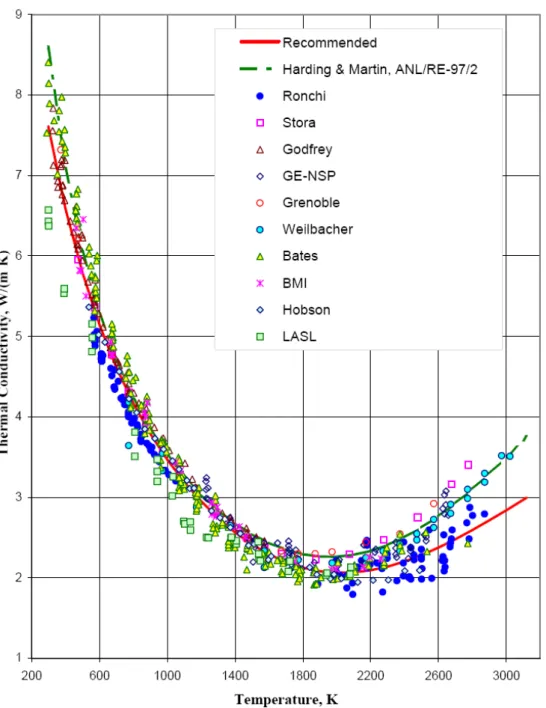
Cladding thermal conductivity and heat capacity ...45
4.2.4.
Sources of Heat during a LOCA accident and other
accidents ...46
4.2.4.1. Decay heat power ... 46
4.2.4.1.1. Value of the ANS standards: decay heat curves ... 47
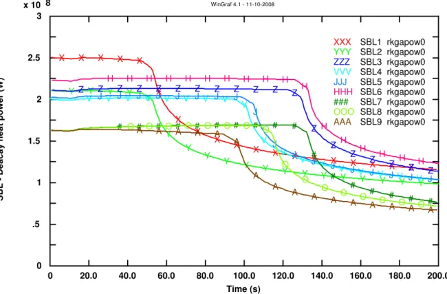
4.2.4.1.2. Application to the SBO and SBLOCA ... 48
4.2.4.1.3. Results of the analysis ... 49
4.2.4.1.4. Decay heat power ... 49
4.2.4.1.5. Hot rod temperature... 55
4.2.4.1.6. Analysis of the results ... 57
4.2.4.1.7. Conclusion ... 57
4.2.4.2. Decay heat: gamma and beta contribution ... 58
4.2.4.2.1. Gamma decay heat source... 58
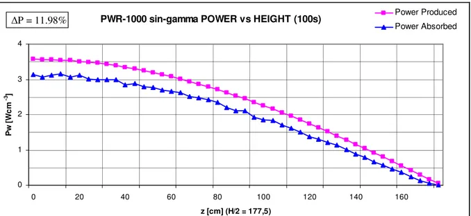
4.2.4.2.2. Gamma peak factor for sinusoidal distribution... 59
4.2.4.2.3. Model and calculation cases... 60
4.2.4.2.4. Evaluation of the cell probability ... 61
VII
4.2.5.
Main sources of uncertainty for evaluating the PCT ...70
4.2.6.
Metal-water reaction rate...71
4.2.7.
Heat transfer from reactor internals ...71
4.2.8.
Primary to secondary heat transfer in Steam Generators
...71
4.2.9.
Thermal parameters for swelling and rupture of the
cladding and fuel rods ...71
4.2.10.
Identification of hottest cladding point in core...72
4.2.11.
Assumption of communication between adjacent
channels ...72
4.2.12.
Critical Heat Flux and Flow-rate...72
4.2.12.1. Analysis performed ... 75
4.2.12.1.1. LOFT analysis... 75
4.2.12.1.2. PWR-1000 analysis ... 78
4.2.12.1.3. Analysis results... 79
4.2.13.
Heat transfer from uncovered rod bundle...80
4.2.14.
Break characteristics and flow ...80
4.2.15.
ECCS bypass ...80
4.2.16.
Noding near break and ECCS injection point ...80
4.2.17.
Frictional pressure drop...80
4.2.18.
Pump modelling...80
4.2.19.
Core flow distribution during blow-down and
post-blow-down thermal hydraulics of a PWR...81
4.2.20.
General Options selection for RELAP5 ...81
4.2.21.
Best estimate nodalization of systems: typical problems
...83
4.2.21.1. Spatial convergence ... 83
4.2.21.2. Specification of state and transport property data ... 84
4.2.21.3. Selection of parameters determining time step sizes.... 84
4.2.21.4. Code input errors ... 84
4.2.21.5. User training ... 86
4.2.21.6. Improved user guidelines ... 87
4.2.21.7. User discipline ... 87
4.2.21.8. Quality assurance ... 87
4.2.22.
Long term cooling for Large Break LOCA...87
4.2.23.
Interactions between primary/secondary systems and
containment ...88
4.2.24.
Fission gases in the fuel gap and number of fissured
rods in transients ...88
4.2.25.
General System assumptions in Best Estimate ...88
5.
DISCUSSION OF THE RESULTS ...89
5.1.
Status of the best estimation applications...89
5.2.
Decay heat power ...89
VIII
5.4.
Cross flow model ...91
5.5.
Summary of the results ...92
6.
CONCLUSIONS...95
REFERENCES ...99
A.1. ANNEX I: BEST ESTIMATE PLUS UNCERTAINTY METHODS....107
A.1.1.
Best estimate plus uncertainty methods ...107
A.1.1.1.
Sources of uncertainty ...108
A.1.1.1.1. Code uncertainty... 109
A.1.1.1.2. Representation uncertainty ... 109
A.1.1.1.3. Scaling ... 110
A.1.1.1.4. Plant uncertainty... 110
A.1.1.1.5. User effect ... 110
A.1.2.
Overview of the uncertainty methods ...111
A.1.2.1.
CSAU Method...112
A.1.2.2.
GRS Method ...113
A.1.2.3.
CIAU method ...114
A.1.2.4.
Other methods ...115
A.1.3.
Supportive methods and software ...116
A.1.3.1.
PIRT ...116
A.1.3.2.
FFTBM ...116
A.1.3.3.
Nodalization qualification...118
A.1.3.4.
Estimation of uncertainties ...119
A.1.3.5.
SUSA ...119
A.2. ANNEX II: ASSIGNAMENT OF SAFETY PRINCIPLES TO
INDIVIDUAL LEVELS OF DEFENCE IN DEPTH ...121
A.3. ANNEX III: EXAMPLES OF APPLICATIONS OF BEST ESTIMATE
METHODS IN LICENSING IN SELECTED COUNTRIES ...125
A.3.1.
Brazil...125
A.3.2.
Czech Republic ...127
A.3.3.
Germany ...129
A.3.3.1.
Application to a German PWR reference reactor, 2 ×
100% cold leg break ...131
A.3.4.
Lithuania...134
A.3.4.1.
MCP pressure header break...134
A.3.4.2.
GDH BLOCKAGE ...135
A.3.4.3.
PARTIAL GDH BREAK...136
A.3.5.
Sweden ...137
A.3.6.
USA Approach to LB-LOCA ...138
IX
A.4. APPENDIX IV: DECAY HEAT ANALYSIS ...141
A.4.1.
Schema and nodalization of the generic PWR...141
A.4.1.1.
References for the data of the NPP nodalization...141
A.4.1.2.
Steady state calculation ...143
A.4.2.
Results on decay heat power...147
A.4.2.1.
Integral of the decay heat power ...147
A.4.2.2.
Derivate of the decay heat power ...150
A.4.2.3.
Heat flux ...152
A.4.2.4.
Reactivity...154
A.4.2.5.
Temperature of the water at the outlet from the core..156
A.4.2.6.
Mass flow-rate...158
A.4.2.7.
Pressure in the upper plenum...160
A.4.3.
Results on decay heat: gamma and beta contribution162
A.4.3.1.
Gamma peak factor for sinusoidal distribution ...162
A.4.3.2.
Evaluation of the cell probability ...164
A.5. APPENDIX V: PEER REVIEW OF THE ICONE 16 PAPER...167
A.5.1.
Abstract ...167
A.5.2.
Michael Bykov and Alexander Moskalev (Gidropress,
Russia)
...167
A.5.3.
Juan Carlos Ferreri (Regulatory body, Argentina) ...167
A.5.4.
Horst Glaeser (GRS, Germany) ...168
A.5.5.
Enno Hicken ...168
A.5.6.
Antonio Madonna (ITER Consult, Italy) ...168
A.5.7.
Borut Mavko, Andrej Prosek (Jozef Stefan Institute,
Slovenia)
...168
A.5.8.
Rizwan Uddin (University of Illinois Urbana –
Champaign, USA) ...170
A.5.9.
Egenijus Ušpuras and Algirdas Kaliatka (Lithuanian
Energy Institute, Lithuania)...170
XI
LIST OF SYMBOLS
AA AVERAGE AMPLITUDE
ACRS ADVISORY COMMITTEE ON REACTOR SAFEGUARD
AEC ATOMIC ENERGY COMMISSION
AEA UNITED KINGDOM ATOMIC ENERGY AUTHORITY
AECL ATOMIC ENERGY OF CANADA LIMITED
AEAW ATOMIC ENERGY AUTHORITY WINFRITH
ALARA AS LOW AS REASONABLY ACHIEVABLE
ANS AMERICAN NUCLEAR SOCIETY
AOO ANTICIPATE OPERATIONAL OCCURRENCE
AP ADVANCED PASSIVE
ASN AUTORITÉ DE SÛRITÉ NUCLÉAIRE
ASAP ADJOINT SENSITIVITY-ANALYSIS PROCEDURE
ASTRUM AUTOMATED STATISTICAL TREATMENT OF UNCERTAINTY METHOD
ATG ATOMIC ENERGY ACT
BE BEST ESTIMATE
BEAU BEST ESTIMATE ANALYSIS AND UNCERTAINTY
BEMUSE BEST ESTIMATE METHODS UNCERTAINTY AND SENSITIVITY EVALUATION
BEPU BEST ESTIMATE PLUS UNCERTAINTY
BIC BOUNDARY INITIAL CONDITIONS
BMU BUNDESMINISTERIUMS FÜR UMWELT, NATURSCHUTZ UND
REAKTORSICHERHEIT (FEDERAL MINISTRY FOR THE
ENVIRONMENT NATURE CONSERVATION AND NUCLEAR SAFETY)
BMWA GERMAN MINISTRY FOR ECONOMY AND LABOR
CNEN COMISSÃO NACIONAL DE ENERGIA NUCLEAR
CATHARE CODE FOR ANALYSIS OF THERMAL HYDRAULICS DURING ACCIDENT AND FOR REACTOR SAFETY EVALUATION
CCFL COUNTER CURRENT FLOW LIMITING
CDF CORE DAMAGE FREQUENCY
CEA COMMISSARIAT A L'ENERGIE ATOMIQUE
CFR CODE OF FEDERAL REGULATIONS
CHF CRITICAL HEAT FLUX
CIAU CODE WITH CAPABILITY OF INTERNAL ASSESSMENT OF
UNCERTAINTY
CNSC CANADIAN NUCLEAR SAFETY COMMISSION
CPS CONTROL PROTECTION SYSTEM
CSAU CODE SCALING, APPLICABILITY AND UNCERTAINTY
CSNI COMMITTEE ON THE SAFETY OF NUCLEAR INSTALLATIONS
DAA DATA ADJUSTMENT AND ASSIMILATION
DH DECAY HEAT
DIMNP DIPARTIMENTO DI INGEGNERIA MECCANICA, NUCLEARE E
DELLA PRODUZIONE
DRM DETERMINISTIC REALISTIC METHOD
ECCS EMERGENCY CORE COOLING SYSTEMS
XII
EUR EUROPEAN UTILITY REQUIREMENTS
EOP EMERGENCY OPERATING PROCEDURE
EPR EUROPEAN PRESSURIZED REACTOR
FC FUEL CHANNEL (IN RBMK NPP)
FFT FAST FOURIER TRANSFORM
FFTBM FAST FOURIER TRANSFORM BASED METHOD
FSF FUNDAMENTAL SAFETY FUNCTIONS
FSAR FINAL SAFETY ANALYSIS REPORT
GASAP GLOBAL ADJOINT SENSITIVITY-ANALYSIS PROCEDURE
GDH GROUP DISTRIBUTION HEADER
GRS GESELLSCHAFT FÜR ANLAGEN UND REAKTORISICHERHEIT
GRNSPG NUCLEAR RESEARCH GROUP SAN PIERO A GRADO
GSUAM GENERIC STATISTICAL UNCERTAINTY ANALYSIS METHOD
HAEA HUNGARIAN ATOMIC ENERGY AUTHORITY
IAEA INTERNATIONAL ATOMIC ENERGY AGENCY
IPSN INSTITUT DE PROTECTION ET DE SÛRITÉ NUCLÉAIRE
IRSN INSTITUT DE RADIOPROTECTION ET DE SÛRITÉ NUCLÉAIRE
ISP INTERNATIONAL STANDARD PROBLEM
ITF INTEGRAL TEST FACILITY
KAERI KOREA ATOMIC ENERGY RESEARCH INSTITUTE
LERF LARGE EARLY RELEASE FREQUENCY
LHGR LINEAR HEAT GENERATION RATE
LOCA LOSS OF COOLANT ACCIDENT
LOFT LOSS OF FLUID TEST
LWR LIGHT WATER REACTOR
MCC MAIN CIRCULATION CIRCUIT
MCP MAIN CIRCULATION PUMP
NAÜ ORSZÁGOS ATOMENERGIA HIVATAL (HUNGARIAN ATOMIC
ENERGY AUTHORITY)
NEA NUCLEAR ENERGY AGENCY
NPP NUCLEAR POWER PLANT
NRC NUCLEAR REGULATORY COMMISSION
OECD ORGANIZATION FOR ECONOMIC CO-OPERATION AND
DEVELOPMENT
PCSAR PRE-CONSTRUCTION SAR
PCT PEAK CLAD TEMPERATURE
PDF PROBABILITY DISTRIBUTION FUNCTION
PIE POSTULATED INITIATING EVENT
PIRT PHENOMENA IDENTIFICATION AND RANKING TABLE
POSAR PRE-OPERATION SAR
PRA PROBABILISTIC RISK ANALYSIS/ASSESSMENT
PSA PROBABILISTIC SAFETY ASSESSMENT
REF REFERENCE
ŘEŽ NUCLEAR RESEARCH INSTITUTE PLC
RG REGULATORY GUIDE
RLBLOCA REALISTIC LB-LOCA
RSK GERMAN REACTOR SAFETY COMMISSION
RTA RELEVANT THERMAL-HYDRAULIC ASPECTS
XIII
SAR SAFETY ANALYSIS REPORT
SB-LOCA SMALL BREAK LOCA
SBO STATION BLACK OUT
SKI SWEDISH NUCLEAR POWER INSPECTORATE
SARA SATATIO SAR
SÚJB STÁTNÍ ÚŘAD PRO JADERNOU BEZPEČNOST (STATE OFFICE
FOR NUCLEAR SAFETY)
SUSA SYSTEM FOR UNCERTAINTY AND SENSITIVITY ANALYSIS
TC TECHNICAL CO-OPERATION
UMS UNCERTAINTY METHODS STUDY
USA UNITED STATES OF AMERICA
WENRA WESTERN EUROPEAN NUCLEAR REGULATORS’ ASSOCIATION
WF WEIGHTED FUNCTION
XIV
LIST OF FIGURES
Fig. 1 – Flow chart for defence in depth [1] ... 1
Fig. 2 –Licensing process: safety requirements ... 6
Fig. 3 – Licensing process: safety assessment ... 6
Fig. 4 – Deterministic safety analysis applications ... 7
Fig. 5 – Deterministic safety analysis: scope ... 8
Fig. 6 – Safety margins... 8
Fig. 7 – Needs for uncertainty: consistent application (development, qualification and application) of a thermo-hydraulic system code ... 9
Fig. 8 – IAEA integrated safety approach [124]... 17
Fig. 9 – IAEA specific safety principles: coherence and interrelations [31]... 18
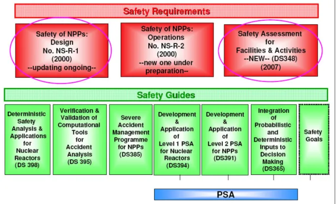
Fig. 10 – IAEA safety standards and other related documents ... 18
Fig. 11 – IAEA safety standards for design ... 19
Fig. 12 – IAEA safety standards in safety assessment and accident management19 Fig. 13 – Structure for defence in depth provisions at each level of defence [33].. 20
Fig. 14 – Interrelation of defence in depth and safety analysis ... 21
Fig. 15 – Interrelation of defence in depth and success criteria ... 23
Fig. 16 – Areas covered by the IAEA Safety Standards for the design of NPPs [96] ... 24
Fig. 17 – Process of granting of authorization ... 25
Fig. 18 – Probability distribution ... 42
Fig. 19 – Heat conductivity: comparison of recommended equation with previous recommendation and data for 95% dense UO2... 43
Fig. 20 – UO2 Heat capacity: comparison of recommended equation and data with MATPRO equation ... 44
Fig. 21 – Recommended fit to zircaloy-2 heat capacity data... 45
Fig. 22 – Comparison zircaloy-2 and zircaloy-4 heat capacities ... 45
Fig. 23- Comparison of revised standard F(t,∞) for 235U (1979) with 1973 standard[90] ... 48
Fig. 24- Total heat power produced in the transient 1 (up to 11000 s) ... 49
Fig. 25- Total heat power produced in the transient 2 (up to 8000 s) ... 50
Fig. 26- Total heat power produced in the transient 1 (up to 400 s) ... 50
Fig. 27- Total heat power produced in the transient 2 (up to 400 s) ... 51
Fig. 28- Total heat power produced in the transient 2 (up to 220 s) ... 51
Fig. 29- Comparison of the total decay heat power produced in the transient 1 (up to 11000 s) ... 52
Fig. 30- Comparison of the total decay heat power produced in the transient 2 (up to 8000 s) ... 52
Fig. 31- Comparison of the total decay heat power produced in the transient 1 (up to 4000 s) ... 53
Fig. 32- Comparison of the total decay heat power produced in the transient 2, SBLOCA (up to 4000 s) ... 53
Fig. 33- Comparison of the total decay heat power produced in the transient 1, (up to 200 s) ... 54
Fig. 34- Comparison of the total decay heat power produced in the transient 2, SBLOCA (up to 200 s with more detailed time step) ... 54
XV
Fig. 35- Hot rod clad temperature in the transient 2 (up to 8000 s) ... 55
Fig. 36- Hot rod clad temperature in the transient 2 (up to 4000 s) ... 55
Fig. 37- Hot rod clad temperature in the transient 2... 56
Fig. 38- Hot rod clad temperature in the transient 2 (up to 160 s) ... 56
Fig. 39- Model of the LOFT and PWR core ... 60
Fig. 40– LOFT sin, 100 s, produced and absorbed power versus radius ... 63
Fig. 41 – LOFT sin, 100 s, produced and absorbed power versus height ... 63
Fig. 42 – LARGE reactor sin, 100 s, produced and absorbed power versus radius ... 64
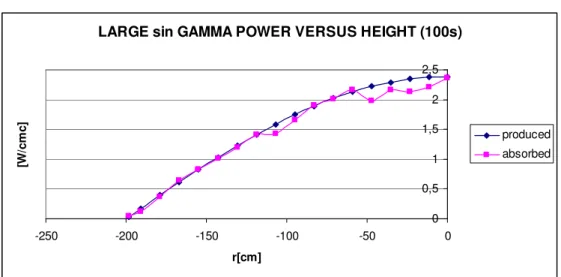
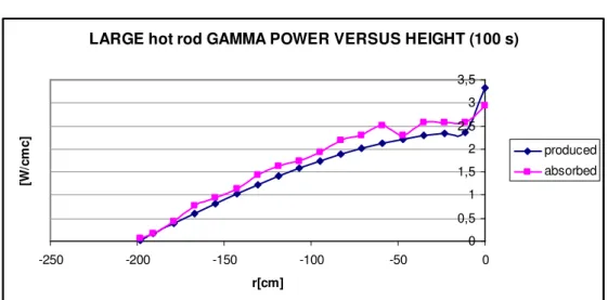
Fig. 43 – LARGE reactor sin, 100 s, produced and absorbed power versus height ... 64
Fig. 44 – LOFT hot rod, 100 s, produced and absorbed power versus radius... 65
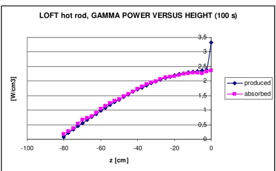
Fig. 45 – LOFT hot rod, 100 s, produced and absorbed power versus height... 65
Fig. 46 – LARGE reactor hot rod, 100 s, produced and absorbed power versus radius ... 66
Fig. 47 – LARGE reactor hot rod, 100 s, produced and absorbed power versus height ... 66
Fig. 48 – LARGE reactor sin, 100 s, produced and absorbed power versus radius fine model... 67
Fig. 49 – LARGE reactor sin, 100 s, produced and absorbed power versus height fine model... 67
Fig. 50 – LARGE reactor hot rod, 100 s, produced and absorbed power versus radius fine model... 68
Fig. 51 – LARGE reactor hot rod, 100 s, produced and absorbed power versus height fine model... 68
Fig. 52 – LARGE reactor sin, 100 s, produced and absorbed power versus radius fine model... 69
Fig. 53 – LARGE reactor sin, 100 s, produced and absorbed power versus height fine model... 69
Fig. 54 – LARGE reactor sin, 100 s, produced and absorbed power versus radius fine model... 70
Fig. 55 – LARGE reactor sin, 100 s, produced and absorbed power versus height fine model... 70
Fig. 56 – CHF comparison, 7 MPa (RELAP5/Mod 2) ... 73
Fig. 57 – CHF Comparison 3 MPa (RELAP5/Mod2) ... 73
Fig. 58 – LOFT: core cross flow model... 76
Fig. 59 – LOFT: core temperature ... 76
Fig. 60 – LOFT: core mass flow ... 77
Fig. 61 – PWR-1000: core cross flow model ... 78
Fig. 62 – PWR-1000: core temperature comparison ... 79
Fig. 63 – PWR-1000: core mass flow rate comparison ... 79
Fig. 64 – Correlation between absorbed and produced energies ratio with mid-height peak width ... 91
Fig. 65 – Uncertainty methods based upon propagation of input uncertainties [87] ... 107
Fig. 66 – Uncertainty methods based upon propagation of output uncertainties [87] ... 108
XVI
Fig. 67 – Uncertainty methodology based on adjoint sensitivity analysis procedure
and data adjustment/assimilation [87] ... 108
Fig. 68 – Evaluation process and main sources of uncertainties [97] ... 109
Fig. A.1 – Result of CIAU Application to Angra-2 LBLOCA Analysis: Uncertainty Bands for Rod Surface Temperature at‘Axial Level 9’ of the Hot Rod Realistic, Obtained by the Reference Run [97] [115] ... 126
Fig. A.2 – Angra-2 LBLOCA Uncertainty Evaluation: Final Result from the CIAU Study and Comparison with Results of the Applicant [97] [115]... 126
Fig. A.3 – Course of the maximum overpressure in hermetically sealed compartments, double-sided tolerance limits, 0 – 35 s [49] ... 128
Fig. A.4 – Pressure difference on the wall of the most loaded BC tray, double-sided tolerance margins, 0 – 5 s [49]... 129
Fig. A.5 – Calculated one-sided 95%/95% uncertainty limit and best estimate reference calculation compared with a “conservative” calculation of rod clad temperature for a reference reactor during a postulated double ended offset shear cold leg break [50] [97] [114]... 132
Fig. A.6 – Sensitivity measures of the reflood PCT with respect to the selected 56 uncertain input parameters (rank correlation coefficient) for the reference reactor large break [50], [97] [114]... 133
Fig. A.7 – Fuel cladding temperatures in 3.0 MW power FC at the location of 2.75 m from the core bottom obtained using SUSA generated runs from RELAP5 calculations [72] ... 134
Fig. A.8 – Real distribution of FC power in the most loaded GDH at 4200 MW power level [72] ... 135
Fig. A.9 – Fuel cladding temperatures in maximum loaded FC, obtained using SUSA generated runs from RELAP5 calculations [72] ... 135
Fig. A.10 – Fuel cladding peak temperatures in maximum loaded FC of the affected GDH calculated using SUSA generated runs [72] ... 136
Fig. A.11 – Schematic processes in the Swedish reactor licensing program... 137
Fig. A.12 – Schematic of steps in the Swedish reactor licensing program ... 138
Fig. A.13 – VVER 1000, Steady State: Up and SGs (1 to 4) pressure ... 143
Fig. A.14 – VVER 1000, Steady State: Core inlet mass flowrate... 144
Fig. A.15 – VVER 1000, Steady State: Core and SG exchanged power ... 144
Fig. A.16 – VVER 1000, Steady State: Surface temperature of hot rod (all elevations)... 145
Fig. A.17 – Relap5 VVER1000 NPP nodalization ... 146
Fig. A.18 – Relap5 VVER1000 NPP nodalization of the core region ... 147
Fig. A.19 – Comparison of the integral of the total decay heat power produced in the transient 1 (up to 11000 s) ... 147
Fig. A.20 – Comparison of the integral of the total decay heat power produced in the transient 2 (up to 8000 s) ... 148
Fig. A.21 – Comparison of the integral of the total decay heat power produced in the transient 1 Magnification (up to 200 s with more detailed time step)... 148
Fig. A.22 – Comparison of the integral of the total decay heat power produced in the transient 2 Magnification (up to 200 s with more detailed time step)... 149
XVII
Fig. A.23 – Comparison of the derivate of the total decay heat power produced in
the transient 1 (up to 200 s) ... 150
Fig. A.24 – Comparison of the derivate of the total decay heat power produced in the transient 2 (up to 200 s) ... 150
Fig. A.25 – Comparison of the derivate of the total decay heat power produced in the transient 1 (between 100s and 900s) ... 151
Fig. A.26 – Comparison of the derivate of the total decay heat power produced in the transient 2 (between 100s and 900s) ... 151
Fig. A.27 – Heat flux in the transient 1 (up to 11000s) ... 152
Fig. A.28 – Heat flux in the transient 2 (up to 8000s) ... 152
Fig. A.29 – Heat flux in the transient 1 (up to 30 s with more detailed time step) 153 Fig. A.30 – Heat flux in the transient 2 (up to 30 s with more detailed time step) 153 Fig. A.31 – Reactivity in the transient 1 (up to 11000s)... 154
Fig. A.32 – Reactivity in the transient 2 (up to 8000s)... 154
Fig. A.33 – Reactivity in the transient 1 (up to 200s)... 155
Fig. A.34 – Reactivity in the transient 2 (up to 200 s)... 155
Fig. A.35 – Temperature of the water in the upper plenum in the transient 1 (up to 11000s) ... 156
Fig. A.36 – Temperature of the water in the upper plenum in the transient 2 (up to 8000s) ... 156
Fig. A.37 – Temperature of the water in the upper plenum in the transient 1(up to 200s) ... 157
Fig. A.38 – Temperature of the water in the upper plenum in the transient 2 (up to 200s) ... 157
Fig. A.39 – Mass flow-rate in the inlet active core in the transient 1 (up to 11000s) ... 158
Fig. A.40 – Mass flow-rate in the inlet active core in the transient 2 (up to 8000s) ... 158
Fig. A.41 – Mass flow-rate in the inlet active core in the transient 1 (up to 300s) 159 Fig. A.42 – Mass flow-rate in the inlet active core in the transient 2 (up to 400s) 159 Fig. A.43 – Pressure in the upper plenum in the transient 1 (up to 11000s)... 160
Fig. A.44 – Pressure in the upper plenum in the transient 2 (up to 8000s)... 160
Fig. A.45 – Pressure in the upper plenum in the transient 1 (up to 1200s)... 161
Fig. A.46 – Pressure in the upper plenum in the transient 2 (up to 1200s)... 161
XVIII
LIST OF TABLES
Tab. 1 – Summary of approaches for performing the safety analysis... 10
Tab. 2 – Demonstration application of BEPU methods [93] ... 29
Tab. 3 – Licensing application of BEPU methods [93] ... 30
Tab. 4 - Various options for combination of a computer code and input data... 38
Tab. 5 - Decay heat transient cases analysed ... 48
Tab. 6 - Comparison of ANS-DECAY inputs in RELAP5/MOD3.2 SBO ... 57
Tab. 7 - Comparison of ANS-DECAY inputs in RELAP5/MOD3.3 SBLOCA ... 57
Tab. 8 - Groups of decay γ photons and energies ... 59
Tab. 9 - Spectrum of Fission Product Decay Gamma Rays at 100 and 10.000 s from the shut down ... 59
Tab. 10 – Gamma cases analysed... 61
Tab. 11 – Results for time after shutdown of 100 s ... 91
Tab. 12 – Summary table ... 93
Tab. 13 – Number of minimum calculations [19] [20] ... 114
Tab. 14 – Reactor Pressure Vessel elevations and main dimensions ... 141
Tab. 15 – NPP System elevations and main dimensions... 142
Tab. 16 – Core elevations and main dimensions ... 142
Tab. 17 – Steam Generator elevations and main dimensions ... 143
XIX
ACKNOLEDGEMENTS
The present work is the product of a long term activity started by the professors and researchers of the Department of Nuclear, Mechanical and Production Engineering (DIMNP) of the University of Pisa and further developed within the Nuclear Research Group of San Piero a Grado (GRNSPG) in cooperation with international scientists, research institutions, industries and international organizations.
A warm acknowledgement goes to all the persons and friends, here not directly mentioned, which introduced me in such technological area. In particular it is well appreciated the help and friendship of:
− W. Giannotti, G. Galassi and M. Cherubini, from the GRNSPG, and N. Forgione, from DIMNP, in introducing me in the thermal-hydraulic codes;
− V. Giusti and R. Ciolini, from the DIMNP, in supporting me in the application of the Monte Carlo code and gamma analyses;
− , M. Bykov, A. Moskalev and A. S. Zubchenko (Gidropress, Russia), J. C. Ferreri (Regulatory body, Argentina), H. Glaeser (GRS, Germany), E. Hicken (Forschungszentrum Jülich, Germany, ) A. Madonna (ITER Consult, Italia), B.
Mavko and A. Prosek (Jozef Stefan Institute, Slovenia), R. Uddin (University of Illinois Urbana – Champaign, USA), E. Uspuras and A. Kaliatka (Lithuanian Energy Institute, Lithuania) to have reviewed all my work and supported me in this experience;
− G. Pilone, as friend, has shared this experience with me.
Finally, a special acknowledgement is for my parents, brothers, sister and sister in law for the family support.
1
1.
INTRODUCTION
Safety is an essential part for the peaceful use of nuclear power generation.
The safety of nuclear power plants is based on the concept of defence in depth [1], Fig. 1, which indicates successive physical barriers (fuel matrix, cladding, primary system pressure boundary and containment) and other provisions to control the release of the radioactive material and on multiple levels of protection against damage to these barriers and against undue radiological impact on the plant itself and its surroundings (level 5, related to emergency plan, has been omitted). It should be noted that in Fig. 1 the events can also not move from a protection level to the next protection level, e.g. a break of the primary coolant pipe (protection level 3) may happen without any abnormal operation (level 2) before.
2
The evaluation of plant safety is transformed in a set of acceptance criteria (such as maximum peak cladding temperature, maximum pressure in the primary system, etc.) to be met under a wide range of plant operating conditions to confirm the preservation of the physical barriers. The acceptance criteria are normally set forth by the national regulator. Their fulfilment is demonstrated by the results of safety analysis documented in the safety analysis report (SAR). To thoroughly evaluate the plant response to a number of unintended events such as operating errors and equipment failures (referred to as postulated initiating events) the use of computer simulation is essential.
The safety analysis is performed to the detail which is determined by the actual knowledge of physical phenomena expected to occur during the accident, by the computer power and computer code availability and experimental and analytical database. In other words the safety analysis has been an evolving process started from simple simulations with simplified models up to today’s complex calculations using advanced computer codes.
In the case of licensing calculations, any insufficiency in safety analysis has to be compensated with additional assumptions. Impact of these assumptions is expected to be conservative, i.e. the results of the analysis are supposed to be worse than real plant response.
The safety analysis tools are broadly used within the framework of the design of new plants and operation of existing plants, including licensing of new NPP projects, safety upgrading programmes of existing NPPs, periodic safety reviews, renewal of operational licences, use of the safety margins for reactor power up-rating, better utilization of nuclear fuel and higher operational flexibility, for justification of lifetime extensions, development of new emergency operating procedures, analysis of operational events, and development of accident management programmes. Significantly increased capacities of new computation technology made it possible to switch over to the new generation of computer codes, with the use of best estimate codes with treatment of uncertainties, and coupling of computer codes.
The procedure to perform the evaluation uncertainty of the best estimate simulation is referred to as best estimate plus uncertainty (BEPU) methodology. Several uncertainty methods based on the concept of BEPU methodology have been developed, implemented and tested and are now in the phase of practical evaluation by the professional community. Recent conclusions state that qualified uncertainty methods are mature for practical applications [2] and [3].
The present document deals with the framework and the strategies for the introduction of BE models into the licensing process.
1.1.
Scope
IAEA Safety Standards recommend, as one of the options for demonstration of sufficient safety margins, the use of best estimate computer codes with realistic input data in combination with evaluation of uncertainties of the calculation results. Best estimate analysis with evaluation of uncertainties is the only way for quantification of the existing safety margins. Its broader use in the future is therefore envisaged, even though it is not always feasible because of the difficulty of quantifying code uncertainties with sufficiently narrow ranges for every phenomenon and for each accident sequence. Since evaluation of uncertainties is
3
a very complex issue, further work in this area is very much needed, in particular towards facilitating broader use of fully best estimate analysis with main response to the spread of the concepts "fixed" in a number of research centers and institutes. As the data and analytical methods quality improves, their application for the licensing calculations becomes eligible. Therefore the regulator has to be capable to expertly review such calculations and eventually even perform independently the peer-review calculations. The profound knowledge and experience with the methodology gives also the regulator the possibility to guide the technical community on its consistent application.
1.2.
Objectives
The objective of the present work is the implementation of the best estimate and uncertainty methods into the licensing process to support a development of the regulatory guides for the application of the BEPU methodology in the licensing calculations.
There are several BE computer codes [34] that are used for the assessment of the safety analysis. They can be grouped in: thermal-hydraulics, structural mechanics and neutronics. Hereafter the thermal-hydraulic ones are used to analyze some thermal-hydraulic transients.
In this thesis, more emphasis is given to the study of “input and method” of BE calculations, more than on “uncertainty evaluation”, which is the main subject of a companion, parallel doctorate work, with which active contacts have been entertained.
The activity has been developed in two parts. Firstly the study is focused on:
− the importance and role of licensing for safety of nuclear power plants and of safety analysis, in particular deterministic safety analysis and safety margins for licensing process;
− the licensing process according to the IAEA standards;
− an overview of existing applications of best estimate methods in licensing practices in selected countries.
Later the work aims to offer an up-to-date discussion basis for the identification of a standard BE procedure to be used with a specific, widely used code (e.g. RELAP5/MOD3), having in mind the objective of a consensus by licensing bodies on a “set to be defined” of safety (uncertainty) margins to be agreed upon for calculations performed using that procedure.
As base on implementing such considerations, the American regulatory guide RG-1.157 is analyzed and some issues, not totally covered by research activities, are developed. In particular, the considerations related to the decay heat, the gamma decay heat distribution and the core cross flow model are supported by calculations using the RELAP5/MOD3 and Monte Carlo MNCP5 codes applied mainly to a generic PWR 1000 ands as preliminary investigation to the LOFT test facility. Therefore, the considerations which follow are not addressed to the simulation of integral test facilities.
The results reported have been shared with colleagues from other countries and institutions.
4
1.3.
Structure
The structure of the report is developed in chapters, that constitute the aim of the report, supplemented by annexes to provide additional information on some related subjects which are over the scope and objective of the thesis. The content of the document is the following:
1) Chapter 2 provides a summary description of the licensing process and of the its current practices.
2) Chapter 3 deals with an up-to-date summary description of the applications of the BE methods in licensing practice either presenting the IAEA standards and giving an overview of the applications in selected countries, i.e. USA, French, Germany, Hungary, Lithuania and Sweden.
3) Chapter 4 is the core of the report. It contains the discussion basis for the identification of a standard BE procedure. It analyzes the RG-1.157 either considering the results of the international researches and developing some calculations on subject like decay heat and cross flow modelling contribution to the PCT.
4) Chapter 5 provides with a discussion on the results achieved. 5) Chapter 6 summaries the results of the thesis.
6) Annex 1 gives an overview of the BEPU methods.
7) Annex 2 gives an example of IAEA assignment of safety principles to individual levels of defence in depth.
8) Annex 3 presents some applications of BE methods in licensing in some countries.
9) Annex 4 deals with reporting some additional results on the calculations performed on the decay heat, gamma and beta distribution.
10) Annex 5 reports the comments received by some colleagues on a paper presented in ICONE 16 related to a part of the work implemented in the thesis. 11) Annex 6 gives a list of publications of the author.
5
2.
LICENSING PROCESS
The utilization of nuclear energy started during the II World War.
For a while its use was strongly restricted to military purposes. Since 1954, the USA Congress passed new legislation that for the first time permitted the wide use of atomic energy for peaceful purposes. The measure directed the AEC "to encourage widespread participation in the development and utilization of atomic energy for peaceful purposes” [30]. At the same time, it instructed the agency to prepare regulations that would protect public health and safety from radiation hazards.
The USA was the main country to develop rules to manage the use of the atomic energy for peaceful applications. They are collected in the 10 CFR 50 [11].
In the 60-ies many countries, dealing with the development of the Nuclear Power Plants (NPPs), implemented their own regulations looking at the NRC licensing process.
In addition to the regulatory bodies, also the nuclear organizations, namely IAEA (International Atomic Energy Agency) and OECD-NEA (Organization for Economic Co-operation and Development – Nuclear Energy Agency), were founded to develop the international cooperation among its member countries nuclear energy for peaceful purposes, “as well as to provide authoritative assessments and to forge common understandings on key issues, as input to government decisions on nuclear energy policy” [40].
2.1.
Importance and role of the licensing for safety of nuclear
power plants
The licensing is the process that guides the life of the NPP from the conceptual design, usually starting from the site definition, up to its decommissioning. It aims to demonstrate the capability of safety systems to maintain fundamental safety functions.
The objectives of the nuclear safety consist on to ensure conditions of localization and of plant such to satisfy the confident protection principles internationally accepted [32], e.g. the IAEA objectives [31]:
− “General Nuclear Safety Objective”: to protect individuals, society and the
environment from harm by establishing and maintaining in nuclear installations effective defences against radiological hazards. It is supported by two
complementary “Safety Objectives” dealing with radiation protection and technical aspects. They are interdependent: the technical aspects in conjunction with administrative and procedural measures ensure defence against hazards due to ionizing radiation:
a) “Radiation Protection Objective: to ensure that in all operational states radiation exposure within the installation or due to any planned release of radioactive material from the installation is kept below prescribed limits and as low as reasonably achievable (ALARA), and to ensure mitigation of the radiological consequences of any accidents;
b) “Technical Safety Objective: to take all reasonably practicable measures to prevent accidents in nuclear installations and to mitigate their consequences should they occur; to ensure with a high level of confidence that, for all possible accidents taken into account in the
6
design of the installation, including those of very low probability, any radiological consequences would be minor and below prescribed limits; and to ensure that the likelihood of accidents with serious radiological consequences is extremely low.
2.1.1. Safety assessment
The licensing process starts with the definition of the safety requirements by the national and political institutions. Considering also the engineering factors relevant for safety, they include general aspects, related to the radiation protection, external and internal hazard, and possible specific systems. It should be clarified that a regulatory body does not justify the introduction of a practice.
The safety requirements provide the input to develop the guidelines for the safety analysis and to perform the safety assessment, Fig. 2.
SAFETY REQUIREMENTS GENERAL ASPECTS -Radiation protection -External hazards -Internal hazards & SPECIFIC SYSTEMS -Containment -CPS -MCC
NATIONAL HEALTH INSTITUTIONS POLITICAL INSTITUTIONS GUIDELINES FOR SAFETY ANALYSIS SAFETY ASSESSMENT ENGINEERING FACTORS IMPORTANT FOR SAFETY
-Operational experience -Loads & Loads combination -Material selection -Equipment qualification -Ageing & wear out
-Human machine interface factor -Quality Assurance
-Use of computational tools -Operator & personnel training
Fig. 2 –Licensing process: safety requirements
The safety assessment in licensing is the process throughout the safety analysis, deterministic and / or probabilistic, providing the safety analysis report and, hence, to the final safety analysis report, Fig. 3.
Fig. 3 – Licensing process: safety assessment
SAFETY ASSESSMENT NUCLEAR AGENCY
DETERMINISTIC SAFETY ANALYSIS PROBABILISTIC SAFETY ANALYSIS SAFETY ANALYSIS REPORT (SAR) FINAL SAFETY ANALYSIS REPORT (FSAR)
7
2.1.1.1.
Deterministic safety analysis
The deterministic safety analysis studies the behaviour of the plant in specific operational and accidental status based on either prudential evaluation or in accordance with the specific safety requirements [32] , Fig. 4 and Fig. 5. It includes the following [33]:
1) confirmation that operational limits and conditions are in compliance with the assumptions and intent of the design for normal operation of the plant;
2) characterization of the PIEs that are appropriate for the design and site of the plant;
3) analysis and evaluation of event sequences that result from PIEs;
4) comparison of the results of the analysis with radiological acceptance criteria and design limits;
5) establishment and confirmation of the design basis; and
6) demonstration that the management of anticipated operational occurrences and design basis accidents is possible by automatic response of safety systems in combination with prescribed actions of the operator.
Fig. 4 – Deterministic safety analysis applications
The applicability of the analytical assumptions, methods and degree of conservatism used should be verified. The safety analysis of the plant design should be updated with regard to significant changes in plant configuration, operational experience, and advances in technical knowledge and understanding of physical phenomena, and should be consistent with the current or ‘as built’ state.
Various applications of deterministic safety analysis
Design and design modifications Licensing
Support for EOPs, Plant simulators
Support for PSA
Support for accident management and emergency planning Analysis of operational events
Regulatory audit analysis Independent verification of safety analysis
Demonstration of capability of safety systems to maintain fundamental safety functions
8 DETERMINISTIC SAFETY ANALYSIS SCOPE PLANT NORMAL OPERATIONS (P=1) ANTICIPATED OPERATIONAL OCCURENCES (10-2< P < 1) DBA (10-4<P<10-2) (TYPICALL) BDBA (10-6<P<10-4) -Radiological doses
to workers and public within limits -Planned release of radioactive materials
-Shutdown the reactor and
maintain in the safe shutdown condition -Remove residual heat
from the core after the shutdown -Reduce the potential for the release of radioactive material -Demonstrate that the release are
below the prescribed limits
-Provide input for off-site emergency planning
-Develop accident management program -Assess the need for features that could be incorporated in the plant design
DETERMINISTIC SAFETY ANALYSIS SCOPE PLANT NORMAL OPERATIONS (P=1) ANTICIPATED OPERATIONAL OCCURENCES (10-2< P < 1) DBA (10-4<P<10-2) (TYPICALL) BDBA (10-6<P<10-4) -Radiological doses
to workers and public within limits -Planned release of radioactive materials
-Shutdown the reactor and
maintain in the safe shutdown condition -Remove residual heat
from the core after the shutdown -Reduce the potential for the release of radioactive material -Demonstrate that the release are
below the prescribed limits
-Provide input for off-site emergency planning
-Develop accident management program -Assess the need for features that could be incorporated in the plant design
Fig. 5 – Deterministic safety analysis: scope
2.1.1.2.
Safety margins
The safety assessment, as well as the safety analysis, can be carried out if the safety limits are defined.
The safety margins provide the difference, in physical units, between the critical value assigned to a parameter, associated with the failure of a system or a component or a phenomena, and the actual value of the parameter (e.g. damage of a barrier in Fig. 6). It should be noted that tipicially, real values are unknown. In consideration of the results of the analyses, the safety margins provide the difference, in physical units, between a threshold, that characterizes an acceptance criterion, and the results provided by either a conservative calculation or a BE calculation. In later case the uncertainty band must be used when defining the safety margins [35].
Fig. 6 – Safety margins
Safety limit (damage of a barrier)
Real value
Safety
margin
Calculated conservative value
Uncertainty range for best estimate calculation
Margin to acceptance criterion
Upper limit of calculated uncertainty range
Best Estimate code results
9
2.2.
Importance and role of safety analysis for licensing
process
Safety analysis represents the principal way to demonstrate the safety of a nuclear installation. It is a systematic process focused at ensuring that all relevant safety requirements are satisfied. Due to the fact that very complex phenomena might occur, sophisticated computer codes have to be used to simulate the plant response to the spectrum of the PIEs. These codes are supposed to handle a broad spectrum of complex physical phenomena including the two-phase flow thermal-hydraulic, heat transfer processes, neutron kinetics, transport of non-condensable gases and simulation of the plant control and safety systems [34]. Development of the computer codes, such as RELAPSE, the predecessor of the RELAP codes series, began in early 1960s. The first attempts leaded to very simple programs with simplified models for the thermal-hydraulics with homogenous equilibrium models of the two-phase flow processes (i.e. liquid and vapor phase having the same temperature and same velocity) and simple heat transfer models. Mediocre knowledge of the processes expected to occur during the plant accidents and transients and weak computing technology restricted the scope of the codes development. The limited knowledge of the simulated processes was compensated by introduction of large amount of conservative assumptions into the code models to assure that real plant response would not lead to more aggravate consequences.
To better understand what is happening during the accident, extensive experimental program was initiated by the technical community with majority of the experiments being performed during a period from late 1960s till early 1990s. Comprehensive summary of this research work is given in US Nuclear regulatory commission (US NRC) compendium [4].
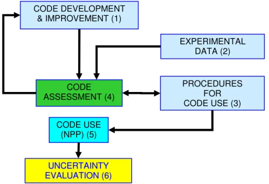
Fig. 7 – Needs for uncertainty: consistent application (development, qualification and application) of a thermo-hydraulic system code
CODE DEVELOPMENT & IMPROVEMENT (1) CODE ASSESSMENT (4) CODE USE (NPP) (5) U UNNCCEERRTTAAIINNTTYY E EVVAALLUUAATTIIOONN((66)) EXPERIMENTAL DATA (2) PROCEDURES FOR CODE USE (3)
10
Today enormous amount of data are available to support code development. Advanced thermal-hydraulic computer codes are programmed on a best-estimate philosophy without any intentional conservative assumptions in the code models. Results of the code simulations show the accepted accuracy when compared with the experimentally measured data, [6] and [7]. Still significant amount of code models rely on the constitutive equations which are naturally accompanied by large uncertainty. There are several simplifying assumptions and approximations, plus further data needed for the code calculations, available only with certain amount of uncertainty. This leads to a necessity of evaluating the uncertainty of the best-estimate simulations, as depicted in Fig. 7. The code development and improvement process, block 1 in Fig. 7, is conducted by “code developers” who make extensive use of assessment (block 4), typically performed by independent users of the code (i.e., group pf experts independent from those who developed the code). The consistent code assessment process implies the availability of experimental data and of robust procedures for the use of the codes, blocks 2 and 3, respectively. Once the process identified by blocks 1 and 4 is completed, a qualified code is available to the technical community, ready to be used for NPP applications (block 5). The NPP applications still require “consistent” procedures (block 3) for a qualified use of the code. The results from the calculations are, whatever the qualification level achieved by the code is, affected by errors that must be quantified through appropriate uncertainty evaluation methodology (block°6) [88].
No. Computer code Initial and boundary conditions components and Availability of systems
1 Conservative Conservative input data Conservative assumptions 2 Best estimate Conservative input data Conservative assumptions 3 Best estimate with uncertainties
Realistic input data with
uncertainties Conservative assumptions 4 Best estimate with uncertainties Realistic input data with
uncertainties
PSA based assumptions
Tab. 1 – Summary of approaches for performing the safety analysis
2.3.
Current practices in the licensing calculations
In all countries using nuclear energy for power production, safety analysis of prescribed set of PIEs has to be performed and documented in the safety analysis report (SAR). SAR is then reviewed and/or approved by the national regulator. Usually predefined structure and content of SAR and approved procedures and methodologies, brought out by the regulator in the form of guide, are followed. Safety analysis in principle consists from the following key components: (a) computer code able to simulate the phenomena expected to occur during the simulating event, (b) the input data representing the simulated nuclear facility – its
![Fig. 13 – Structure for defence in depth provisions at each level of defence [33] 3.1.1.2](https://thumb-eu.123doks.com/thumbv2/123dokorg/7332865.91028/42.892.103.791.454.932/fig-structure-defence-depth-provisions-level-defence.webp)