Facoltà di Ingegneria dei Processi Industriali
Degree in Materials Engineering
3D Reinforcement of Composite
Materials
Supervisors:
Valter Carvelli
(Politecnico di Milano)
Giulio Ventura
(Politecnico di Torino)
Carlo Poggi
(Politecnico di Milano)
Corinna A Conway
750155
Dedicated to my little brother, Michael Conway
Who taught me how precious life truly is and what it means to follow
your dreams.
And to My Parents, Robert and Theresa Conway
Who made this all possible through their love and
Table of Contents
Abstract
13
Summary
14
Chapter 1
Introduction to Composites
16
1.1 Introduction 16 1.2 Fiber Reinforced Composites (FRC) 16 1.2.1 The Matrix 17 1.2.2 The Fibers 17 1.3 Reinforcement Architectures 19 1.3.1 2D Composites 20 1.3.2 3D Composites 21 References 22
Chapter 2
Reinforcement Fabric Manufacturing
23
2.1 Introduction 23
2.2 Weaving 23
2.2.1 2D Weaving 23 2.2.2 3D Weaving 25
2.2.3 3D Orthogonal Non-‐Woven, Multiaxial Weaving
and Distance Fabrics 26
2.3 Braiding 27
2.3.1 2D Braiding 27 2.3.2 Two and Four Step 3D Braiding 27 2.3.3 Multilayer Interlock Braiding 28
3.2 Composite Consolidation techniques 32 3.2.1 Resin Transfer Molding 32 3.2.2 Resin Film Infusion 32
3.2.3 SCRIMP 34
3.3 Consolidation Equipment 34 3.3.1 Tooling (mold) 35 3.3.2 Heating and Cooling 35 3.3.3 Injection Equipment 36
3.4 Optimization 36
References 39
Chapter 4
Textile Fiber Reinforcement Properties
40
4.1 Introduction 40
4.2 In-‐Plane Shear 40 4.3 In-‐Plane Biaxial Tension 42
References 44
Chapter 5
Composite Modeling
45
5.1 Introduction 45
5.2 Fundamentals 46 5.3 Representative Volume 48 5.4 Rule of Mixtures 50 5.5 Basic Models for 2D Woven Composites 51 5.5.1 Mosaic Model 51 5.5.2 Undulation Model 53
5.6 Models for 3D Woven Composites 56 5.6.1 Orientation averaging 57 5.6.2 Iso-‐Strain and Iso-‐Stress Model 57 5.6.3 Finite Element Model 60
References 61
Chapter 6
3D Woven Composites
63
6.1 Introduction 63
6.2 3D Woven Composites 63 6.2.1 Microstructure Features and Crimp 63 6.2.2 Tensile Properties 66 6.2.3 Compressive Properties 67 6.2.4 Flexural and Interlaminar Shear Properties 68 6.2.5 Interlaminar Fracture 68 6.2.6 Impact Damage Tolerance 69
References 71
Chapter 7
3D Braided, Knitted, Stitched and
Z-‐Pinned Composites
72
7.1 Introduction 72 7.2 3D Braided Composites 72 7.2.1 In-‐Plane Properties 72 7.2.2 3D vs. 2D Braided Composites 73 7.3 3D Knit Composites 73 7.3.1 In-‐Plane Properties 73 7.3.2 Interlaminar Fracture and Impact Toughness 75 7.4 Stitched Composites 75 7.4.1 In-‐Plane Mechanical Properties 76Figures
Figure 1.1: Depiction of fiber type, and non-‐woven composite
architectures 18
Figure 1.2: Layup sequence 18
Figure 1.3: Stress vs. Strain graph comparing Carbon (green),
Glass (purple) and Aramid (red) fiber properties 19
Figure 1.4: Braided, woven and knit fabric structures 20
Figure 1.5: Comparison of in-‐plane and through-‐thickness
Properties 21
Figure 2.1: Traditional weaving loom 24
Figure 2.2: Illustration of yarn structure, and common weave
Patterns 25
Figure 2.3: 3D weave geometries 26
Figure 2.4: Illustrating the ability to weave slits into the fabric
capable of creating three-‐dimensional structures 26
Figure 2.5: Multilayer interlock braided fabric 28
Figure 2.6: 3D knit fabric 29
Figure 2.7: Stitched fabric 30
Figure 2.8: Z-‐pinning process 30
Figure 3.1: RTM 33
Figure 3.2: RFI 34
Figure 3.3: Autoclave for composite consolidation. Image
provided by AAC research 35 Figure 3.4: Viscosity vs. Time – temperature dependence
of thermoset TGDDM resin. Image taken from Understanding
of Rheology of Thermosets 37
Figure 4.1: Biaxial tension test (left) and Picture frame test (right) 41
Figure 4.3: Illustrating non-‐linear behavior of woven fabric 42
Figure 4.4: Biaxial testing Machine 42
Figure 4.5: Biaxial testing sample 43
Figure 4.6: Clamps 43
model. b) Division of the unit cell into 4 blocks 58
Figure 5.8: Possible assembly directions of block A and B 58
Figure 5.9: Example of a 3D FE model of a unit cell of a 3D
orthogonal Woven composite material 60 Figure 6.1: Tensile strength at different stages of the weaving
Process 64
Figure 6.2: Illustration of the crimping in 2D woven fabrics 65
Figure 6.3: difference between Idealized z-‐binder geometry (a)
and actual (b) 65
Figure 6.4 Top and cross sectional view 66
Figure 6.5: Kinking failure in compression 67
Figure 6.6: Mode I delamination cracking 68
Figure 6.7: Effect of impact velocity on delamination damage of
2D and 3D woven composites 69
Figure 6.8: Effect of impact energy on flexural strength 70
Figure 6.9: Effect of impact energy on the compressive strength 70
Figure 7.1: Warp knit (a) Denbigh, (b) 1x3 single cord, and (c) 1x4
single cord architectures 74
Figure 7.2: Wale and course directions as well as warp and
weft fabric structure. 75 Figure 7.3: Illustrating mode I interlaminar toughening
mechanism of stitched composites 76
Figure 7.4: Depiction of z-‐pinned architecture at insertion site 77
Figure 7.5: Depiction of weaving and deflection caused by z-‐pins 78
Tables
Table 1.1: Matrix materials costs, application temperature and
toughness. (TP – thermoplastic and TS – thermoset) 14 17
Table 1.2: Glass type and defining characteristics 19
pattern and edge conditions 73 Table 7.2: Tensile properties of warp knit with varying knit
architectures 74
Table 7.3: Tensile properties of weft knit with varying knit
Abstract
Composite materials present a unique opportunity to engineer a material in order to optimize its physical, thermal and mechanical properties for specific applications. Offering many advantages such a relatively high specific strength, stiffness, fatigue resistance and corrosion resistance with respect to weight. Due to their exceptional qualities, composites can be found in many applications, from aircrafts, helicopters and spacecrafts to submarines, automobiles and sporting goods. However their wide spread use has been inhibited by their high cost, poor delamination toughness, and poor impact damage resistance. Many prospects have been investigated as methods for improving these characteristics, however composites reinforced with 3D fabric architectures appear to be the most promising solution. Here an investigation of 3D fabric architectures (3D woven, braided, knit, stitched and z-‐pinned), manufacturing methods, and composite properties are reviewed in order to have a better understanding of the pros and cons of such a material as well as potential improvements and opportunities. As expected 3D composites solve many of the problems faced by 2D composites, however these improvements are accompanied by the deterioration of in-‐plane properties. Many 3D composites show potential for applications unsuited for 2D composites, however optimization of 3D fabric manufacturing, composite production, and in-‐ and out-‐ of-‐plane properties needs further investigation.
a corrosione se confrontati col peso. A causa delle loro qualità eccezionali, i compositi possono essere trovati in molte applicazioni: dagli aeroplani, elicotteri e veicoli spaziali ai sottomarini, automobili e merci sportive. Purtroppo la loro larga diffusione è limitata dal loro alto costo, piccola durezza alla laminazione e piccola resistenza all'impatto. Molti aspetti sono stati investigati come metodi per migliorare queste caratteristiche, comunque i compositi rinforzati con architetture di tessuti 3D appaiono essere la soluzione più promettente. Un approfondimento sui metodi di produzione, modellazione, e le proprietà dei compositi di tessuti 3d, 3d intreccaiti, cuciti e z-‐appuntati architetture di rinforzo è stata eseguita in modo da capire meglio i pro e contro di questi materiali così come possibili miglioramenti e opportunità.
Molti miglioramenti sono ancora necessari per la produzione di tessuti di rinforzo 3D. I tessuti e i tessuti intrecciati possono essere prodotti usando speciali macchine o modificando i tradizionali macchinari 2D. Comunque le architetture e i costi e i volumi di produzione sono correntemente limitati dalle tecnologie disponibili. RTM (Resin transfer molding) and RFI (Resin film
infusion) or SCRIMP sono i metodi più efficienti per la corrente produzione di compositi 3D. Ogni metodo ha diversi benefici e limitazioni. Una revisione di base degli attuali metodi di prova e modellazione per i compositi 3D è presentata nei capitoli 4 e 5.
Come ci si aspetta i compositi 3D risolvono molti dei problemi che hanno i compositi 2D, comunque questi miglioramenti sono accompagnati dalla
deteriorazione delle proprietà nel piano. L'ottimizzazione della manifattura dei tessuti 3D, la produzione di compositi, e le proprietà nel piano e fuori dal piano hanno bisogno di ulteriori investigazioni, comunque molti compositi 3D
mostrano potenzialità per diverse applicazioni per cui non possono essere usati compositi 2D. Per esempio, cuciture e z-‐pinning mostrano eccezionali
potenzialità per il rinforzo dei giunti, mentre I tessuti a maglia 3D mostrano un eccellemte resistenza all'impatto e sono di particolare interesse per l'uso nelle protesi ma non sono utilizzabili per applicazioni strutturali.
1
Introduction to Composites
1.1 Introduction
Over the past years composites have become increasingly popular. Their popularity is due to their ability to be manipulated and engineered in order to optimize physical, thermal and mechanical properties for specific applications. The mechanical properties of a composite depend on both the material selection as well as the orientation of the reinforcements within the component. For example, fiber direction may be dictated in order to optimize the mechanical properties of the material in a given direction and materials can be selected to optimize performance in diverse environments. Composites are also advantageous from a weight perspective, as they display a relatively high specific strength, stiffness, fatigue resistance and corrosion resistance with respect to weight. Therefore they are usually chosen for applications where high operational properties are crucial and weight management is critical. Due to their exceptional qualities, composites can be found in all types of applications, from aircrafts, helicopters and spacecrafts to submarines, automobiles and sporting goods.1,2
1.2 Fiber Reinforced Composites (FRC)
The definition of a composite material is that it must be made up of at least two distinguishable constituents demonstrating significantly different chemical or physical properties. The combination of these constituents into a composite creates a new material that displays a set of properties different from the individual properties of each of the constituent materials. There are many different composite types, however for the purpose of this thesis we will focus on Fiber Reinforced (FR) Composites. FR composites consist of a matrix, usually a rigid polymeric material embedded with fiber reinforcements. The polymeric material of the matrix is made from either a thermoplastic (e.g. polyamide, polypropylene, etc) or a thermoset (e.g. polyimides, epoxy, etc.) material, while the reinforcing fibers are usually made from glass, carbon or aramid.1,2
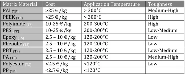
handle due to their high viscosity. Thermoset matrix materials are characterized by their low viscosity and low processing temperature with drawbacks in application temperature, and toughness (see Table 1.1).
Matrix Material Cost Application Temperature Toughness
PAI (TP) >25 €/kg > 300°C Medium-‐High PEEK (TP) >25 €/kg > 300°C High Polyimide (TS) 10-‐25 €/kg 200-‐300°C High PES (TP) 10-‐25 €/kg 200-‐300°C Low-‐Medium Epoxy (TS) 2.5 – 10 €/kg 120-‐200°C Low Phenolic (TS) 2.5 – 10 €/kg 120-‐200°C Low PBT (TP) 2.5 – 10 €/kg 120-‐200°C Low-‐Medium PA (TP) 2.5 – 10 €/kg 120-‐200°C Medium-‐High Polyester (TS) <2.5 €/kg <120°C Low PP (TP) <2.5 €/kg <120°C
Table 1.1: Matrix materials costs, application temperature and toughness. (TP – thermoplastic
and TS – thermoset) 3
1.2.2 The Fibers
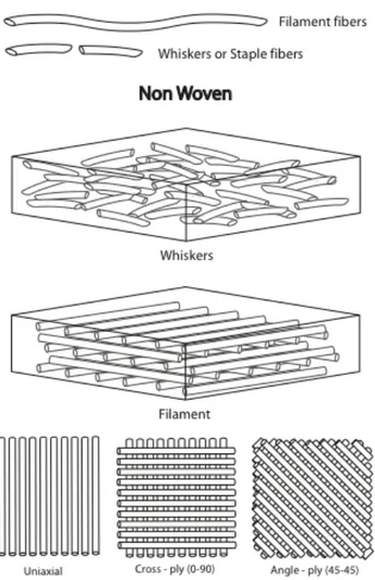
The fibers of the FR composite can be varied in size, shape, length, direction, architecture, and material in order to engineer a composite to the have specific properties. The length of the reinforcing fibers can be whiskers (short/staple) or continuous (filament) (Figure 1.1), and usually have an ovular or circular cross-‐sectional shape, although almost any shape is possible. Whisker reinforcement fibers are used to create non-‐woven, non-‐structural composites. When randomly oriented in the matrix material they create an isotropic composite, while orienting the fibers can give more strength in the orientation direction, generating an anisotropic composite.
Figure 1.1: Depiction of fiber type, and non-‐woven composite architectures
On the other hand, using filament fibers makes it possible to engineer the reinforcement architecture. This can be achieved through the prepreg lay-‐up, or by using woven, braided, stitched, or z-‐pinned fabrics. A prepreg is a unidirectional fiber sheet impregnated with uncured matrix resin. The layup of the prepregs determines the fiber orientations within the composite (see figure 1.2). Fibers may be oriented in one direction (e.g. 0°/0°/0°/0°) giving unidirectional characteristics, or in multiple directions (e.g. 0°/+45°/-‐45°/90) creating quasi-‐isotropic properties.1
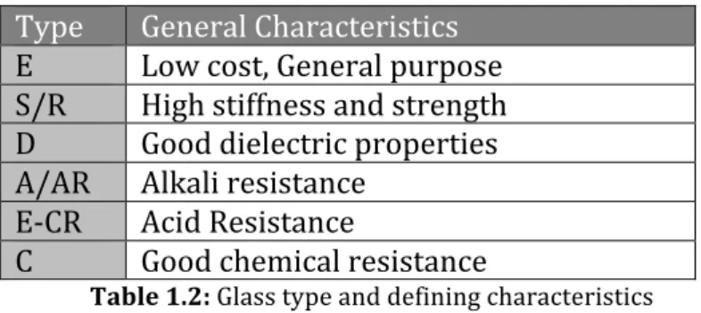
Type General Characteristics
E Low cost, General purpose S/R High stiffness and strength D Good dielectric properties A/AR Alkali resistance
E-‐CR Acid Resistance
C Good chemical resistance
Table 1.2: Glass type and defining characteristics
Carbon fibers are becoming more popular and are of high interest due to their high modulus, high strength, and low density/weight, however they are still extremely expensive.
Figure 1.3: Stress vs. Strain graph comparing Carbon (green), Glass (purple) and Aramid (red)
fiber properties. 3
Aramid fibers have advantages in its high toughness, high strength and low cost, but suffer from low UV resistance, and low compressive strength (although the low compressive strength can be used to an advantage in certain applications). These are the three most common fiber reinforcement materials, whose tensile behavior are compared in Figure 1.3. However it is important to note, that boron, basalt and ceramic fibers have also been used to a much lesser extent.1,2
1.3 Reinforcement Architectures
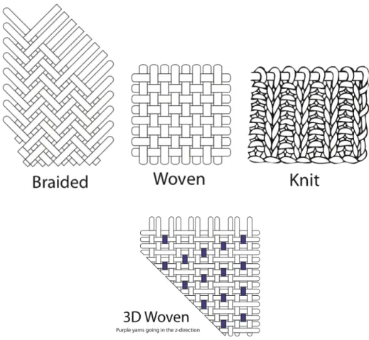
Using more complex reinforcement architectures gives another engineering possibility. Woven, knit, braided, stitched, and z-‐pinned architectures provide
the most interesting opportunities at the moment (figure 1.4). Within each fabric production process there are many different architectures that can be achieved. For example with 3D weaving we can produce angle interlock weaves, orthogonal weaves or through-‐thickness interlock weaves. The properties of each of these fabrics differ greatly, therefore the fabric itself can be engineered for the desired properties.1,2
Figure 1.4: Braided, woven and knit fabric structures
1.3.1 2D Composites
2D laminated composites are among the most common composites used in the market today. In applications requiring high performance properties filament fibers are selected over whiskers and are oriented in the x-, y-directions of the composite. Some of the major disadvantages of 2D composites lie in their high cost, and low through-thickness mechanical properties due to the lack of z-directional fibers. Therefore the mechanical properties in the through-thickness direction are determined by the mechanical properties of the resin and the fiber-resin interface. A comparison of the in-plane and through-thickness strengths of 2D laminates, seen in figure 1.5 below, reveals that the through-thickness properties are usually less than 10% of the in-plane properties and therefore cannot be used in applications supporting high through-thickness or inter-laminar shear loads.2
Figure 1.5: Comparison of in-plane and through-thickness properties1
Another issue with 2D composites is their poor impact damage resistance, delamination and the loss in mechanical properties caused by impact. A composite subjected to an impact in the through-thickness direction can suffer from degraded in-plane mechanical properties under tension, compression, bending and fatigue. Due to the threat of delamination, composite parts are often over-engineered by adding thickness, resulting in increased costs, weight and volume.2
Alternatives to improve through-thickness delamination resistance and post-impact mechanical properties include chemical and rubber toughening of resins, chemical and plasma treatment of fibers, and interlaying using though thermoplastic films. They have all shown improvements in low energy impacts but have other drawbacks, which have lead to the limitation of their use in large structures.2
1.3.2 3D Composites
3D composites were introduced as a solution to the main disadvantages of 2D composites: high fabrication costs, proneness to through-‐thickness delamination and low impact damage tolerance. Unlike the 2D composites, 3D composites have fibers in the x-‐, y-‐, and z-‐directions. The z-‐directional or z-‐ binder yarn is responsible for the increase of these out-‐of-‐plane mechanical properties. 3D composites can be made from 3D woven, braided, or knit fabrics as well as stitched and z-‐pinned fabrics. The rest of this thesis will cover 3D composites and their reinforcements. The following chapters will review their manufacturing, composite consolidation, modeling and properties.2
References
1. M. Sc. Badawi, Said Sobhey A. M. Development of the Weaving Machine and 3D Woven Spacer Fabric Structures for Light Weight Composites Materials. Dresden Technical University. 2007
2. Tong, L. Mouritz, A.P. and Bannister, M.K. 3D Fibre Reinforced Polymer Composites. Elsevier Science Ltd. Oxford, UK. 2002.
3. Poggi, Carlo. Composites For Structural Application. Politecnico di Milano. Course, 2nd Semester 2011
2
Reinforcement Fabric Manufacturing
2.1 Introduction
The manufacturing of the 3D fabric reinforcement plays a very important role in the growth of the 3D fiber reinforced composite industry. It is only through economical production of the 3D reinforcement that wide spread use can be achieved. There are many different ways in which to manufacture a 3D fabric reinforcement, however the most common methods, and those that will be discussed here, are: weaving, braiding, knitting, stitching, noobing, and z-‐ pinning. 2,3
2.2 Weaving
Weaving is one of the oldest forms of fabric production and is already used extensively within the composite industry. However, the fabrics currently being used are mostly 2D and not 3D. The weaving process, at the moment, allows for the production of fabric widths between 1.8 – 2.5 meters at a rapid production rate making this type of reinforcement good for components requiring large surfaces and fast production rates. An appealing aspect of the current weaving process is that the 2D weaving equipment can be easily altered, at little cost, to attain the ability of producing 3D fabrics, however yarn directions are restricted to 0 and 90 degree directions. 1,3
2.2.1 2D Weaving
Let us begin with a description of the traditional 2D weaving process, as the 3D process is based off of its simpler counterpart. Weaving is the act of interlacing two sets of yarns to produce a fabric2. The steps of weaving are in the
order of shedding, picking, beating up and taking up3. At this point it is
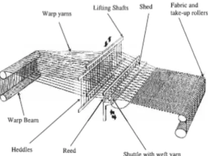
important to note that there are different types of weaving looms, the traditional looms (Figure 2.1) that can produce fabrics of plain weave, twill and satin, and those called, jacquard looms, which can produce complicated fabric patterns. Jacquard looms have a lifting mechanism controlled by a computer in which individual warp yarns can be lifted at any time allowing for intricate patterns to be woven into the fabric, these are of particular interest in the 3D weaving process. 1,2,3
Figure 2.1: Traditional weaving loom3
The weaving process starts by threading or feeding the warp yarns, those that run in the machine direction – 0 degrees, into the loom from the source yarns. The source yarns are run through a series of rollers in order to maintain and control the tension. These yarns are then fed through the lifting mechanism. The lifting mechanism lifts the warp yarns in order to create a space, or shed, for the weft yarns to be inserted. The weft yarns are those running horizontal to the machine, or in the 90 degree direction. The sequence in which the warp yarns are lifted and the weft yarns inserted creates the pattern of the fabric (see Figure 2.2). It is important to note that the fabric architecture greatly influences the mechanical properties and drapability of the fabric and is highly dependent on the weave pattern, fiber or tow size, weft and warp yarn concentration, yarn tension, and tightness of the tows.1,2,3 Plain weave being the stiffest (least
drapable) and weakest, while satin is the strongest and most drapable.3
Figure 2.2: Illustration of yarn structure, and common weave patterns
Picking is the process of inserting the weft yarns in the shed created by the lifting mechanism.2 This can take place in a number of different ways. The oldest
technique for insertion of the weft yarns is through the use of a shuttle to transport the yarns through the shed. This technique is slow, but creates a closed edge fabric. Open edged fabrics can be produced at much quicker rates, using a mechanical arm, rapier, or high-‐pressure air or water to transport the weft yarns through the shed.3 The next step is the beating up process, in which
the inserted weft yarns are compacted using a comb-‐like devise, the reed. Finally, in order to have a continuous process the fabric is advanced forward by a series of positively driven rollers, this is called take-‐up. This process is continued until the desired length of fabric is created. The fabric can be produced continuously and cut into the lengths needed. Also different types of yarns can be used for warp and weft to help created a fabric better suited for the intended use. 1,2,3
2.2.2 3D Weaving
The major difference between 2D and 3D woven fabrics is the need of multiple layers of warp yarns in the 3D fabrics. This tends to be a major disadvantage, as the need for a large number of warp-‐ends and the time required to prepare the loom can be very costly. Therefore, at the moment, most 3D woven fabrics are used in the production of narrow products reducing the number of warp yarns required. As stated above, the traditional weaving equipment can be easily altered to create a 3D woven fabric. The first modification is to use a lifting mechanism with multiple eyes, allowing for layered warp yarns. Jacquard looms are normally selected for the production of 3D woven fabrics, given the distinct advantage of improved control of the lifting mechanism. With the multiple layers of warp yarns, comes the creation of multiple sheds. This allows for multiple insertions of the weft yarns at the same time, and is the second modification needed in order to have 3D weaving. 1,2,3
In the formation of a 3D woven fabric, pockets are formed between any four adjacent warp yarns. These pockets can be filled with stuffer yarns that do not interlace with the weft yarns. The pockets can be filled according to mechanical needs and in this way the fabric can be further engineered to specific applications. In order to maximize performance, majority of the yarns are designed to lay flat, and only select warp yarns are used to bind the layers together. Examples of the weaving architectures capable of being produced using the 3D weaving procedure are given in the figure 2.3. Please note that
these fabric architectures are idealized and not possible in reality. Woven materials can be produced in types of solid, shell, tubular and/or combinations of these. 1,2,3
Figure 2.3: 3D weave geometries2
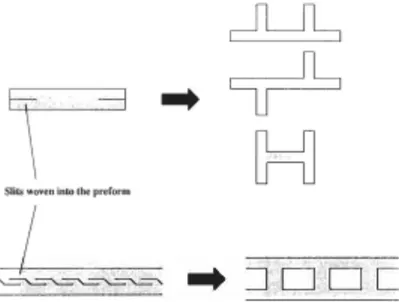
As with 2D weaving, 3D weaving is limited to yarn placement in the 0 and 90 degree directions. Therefore its use is limited to components that are not subjected to extensive shear and torsion stresses. An advantage of the weaving loom is its capability of producing fabrics with slits that can then be opened into three-‐dimensional structures (see figure 2.4). This can be used to produce I beams and boxes using flat fabric and have already been used in civil engineering components. 3
Figure 2.4: Illustrating the ability to weave slits into the fabric capable of creating three-‐
dimensional structures.3
Examples of 3D weaving equipment include, 3WEAVE created by 3tex. This machine allows for the use of multiple filling layers at a time, use of carbon, aramid, glass, polyethylene, steel fibers, etc., produce a fabric thickness up to 25.4 mm, and a fabric width of 1830mm. 2
Distance fabrics are produced using a similar processed used in the production of velvet. There are two sets of warp yarns, spaced at specified distance apart, that are woven as separate fabrics and at the same time interlinked by transferring specific warp yarns, pile yarns, between the layers. This fabric is important for the production of peel-‐resistant and delamination resistant sandwich composites. 3
2.3 Braiding
Braiding is also commonly found in the production of many composite components: golf clubs, yacht masts and aircraft propellers. Unlike weaving, braiding allows for a much larger selection of shapes, however is not capable of producing large volumes of wide fabrics, therefore is better suited for the production of highly specialized parts. The disadvantages of braiding fall in the limited size of performs compared to the size of the equipment as well as the limited length of the preform before the yarns need to be refilled. 3
2.3.1 2D Braiding
2D braiding is usually preformed by a set of yarn carriers that counter rotate around a circular frame to form the braided fabric. Braided fabric is characterized by the high level of yarn interlinking and is formed as either a tubular or flat fabric. A large benefit of the braiding process is that braiding can be preformed over a mandrel in order to produce intricate perform shapes. The shapes achievable can have varying cross sectional shapes, varying dimensions along their length, and attachment points or holes can also be incorporated into the preform. By incorporating holes and attachment points it is possible to cut costs in component finishing as well as improve mechanical performance by allowing for unbroken fibers at the attachment sites. Another large benefit of the braiding process is the ability to produce fabric, containing yarns at angles other than 0/90 degree directions.3
2.3.2 Two and Four-Step 3D Braiding
The 2D braiding equipment is insufficient to produce 3D braided fabric. One of the first 3D braiding processes, was developed by General Electric and is known as the four-‐step or row and column braiding. This process involves a flat bed containing rows and columns of yarn carriers that form the preform shape. The name comes from the requirement of four separate sequences of row and column motion in order to produce the braided fabric or perform. In this process, the yarns are mechanically compacted after each step, similar to the
weaving process. The braiding process can be controlled in order to produce diverse braid patterns and allows for high control over mechanical properties of the preform in the three principal directions.3
Later the technology was developed into a cylindrical configuration known as, Through-‐the-‐Thickness braiding. This is achieved by having identical rings arranged side by side in an axial arrangement. The rings allow the yarn carriers to move from ring to ring in the axial direction while the rings rotate to perform braiding. Cylindrical braiding equipment is advantageous in space saving.3
Another form of braiding exists in the two-‐step process. In this process majority of the yarns are fixed in the axial direction, and a small number of yarns are used to braid. The shape of the perform can be controlled by the arrangement of the axial carriers. Here the braiding carriers move completely through the structure between the axial yarns. It is advantageous in that any shape can be achieved, and there is no need for mechanical compaction of the yarns reducing the risk of damage.3
2.3.3 Multilayer Interlock Braiding
This method of 3D braiding is most similar to the traditional 2D braiding processes. The equipment is comprised of a cylindrical braiding frame containing parallel braiding tracks with yarn carriers that can be transferred between the tracks, allowing for the interlocking of the adjacent layers. This version of 3D braiding is advantageous in that the interlocking yarns are in the plane of the structure and therefore allow the preform to maintain most of the in-‐plane properties. However, to achieve the same number of yarn carriers the multilayer interlocking braiding equipment needs to be larger, and the equipment is less adaptable. Figure 2.5 illustrates multilayer interlock braided fabric.3
Figure 2.5: Multilayer interlock braided fabric3
2.4 Knitting
sections of straight yarns to improve in plane mechanical properties. Further developments in the electronic control of the needles have allowed for the component to be knit in a way that allow for the final 3D shape to be formed automatically without further alteration after the knitting process, without excessive waste. 3
Figure 2.6: 3D knit fabric3
The traditional forms of knitting are either warp of weft knitting. In weft knitting there is only a single yarn fed into the machine at a 90-‐degree direction with respect to the fabric production. The yarn forms a line of interlocking loops to form the knit fabric. While with warp knitting, there are a number of yarns feed into the machine at the 0 degree direction with respect to the fabric production. With warp knitting, multiple types of yarns can easily be knit together, however more yarn bundles will be needed and therefore can be more costly. The interlocking of the loops is achieved through a needle bed, a row of closely spaced needles that pull the yarns through the previously knit loops. Machines with two or more needle beds are capable of creating 3D knit fabrics. 3
2.5 Stitching
Stitching is the simplest and cheapest of the methods for producing a 3D fabric architecture. The process involves the insertion of a needle carrying a z-‐ directional yarn through layers of 2D fabric, in effect stitching the layers together and creating a 3D architecture (see figure 2.7). The z-‐binding yarns are most commonly aramid. This is due to their high toughness as well as equipment requirements. Current stitching machinery may be used with aramid yarns
without further alterations. However attention must be given to their tendency to absorb moisture and insufficient binding to many common polymer resins.3
Figure 2.7: Stitched fabric3
Creating 3D architectures through stitching provides many benefits. Among those is the possibility to use the process with traditional 2D woven, braided, knit, etc. prepregs. This allows for a great degree of flexibility in the fabric lay-‐up; using different material layers, as well as different yarn directions. Also, stitching can be placed only in the areas that require reinforcement in the z-‐ direction, as well as complex stitching patterns by using current embroidery machinery and software. Another great advantage is the ability to create complex 3D shapes by stitching different component parts together.3
The main disadvantages with this process lay in the reduction of the in-‐ plane properties. This is due to local fiber damaged caused by the needle insertion, increased crimp induced by the z-‐directional yarns, and resin-‐rich pockets formed by the bunching of fibers contained by the stitching yarns.3
2.6 Z-pinning
Z-‐pinning is used as an alternative method to stitching. The process uses pre-‐cured reinforcement fibers, which are embedded in a thermoplastic foam and placed on top of the prepreg or dry fabric. The prepreg and foam are then prepared for curing. During the curing process, the thermoplastic foam collapses and the pressure slowly drives the reinforcing fibers into the component (see figure 2.8). With z-‐pinning, there is less crimping induced by the z-‐directional reinforcing fibers as well as less damage to the yarns in the prepreg, while still maintaining the high level of control over reinforcement placement.3
3
Composite Manufacturing
3.1 Introduction
There are many different ways in which to consolidate the preform to create the final composite component, however not all of these processes are suited for 3D preform consolidation. Methods such as hand impregnation, pultrusion, and commingled yarns greatly distort the fabric architecture during composite consolidation, significantly diminishing the final mechanical properties of the component. Therefore, in order to reap the benefits of the 3D preform production technologies, the correct consolidation technology must be chosen. At this moment the only manufacturing process that is successful in consolidating 3D fiber performs is Liquid Molding (LCM). This is due to its high flexibility regarding component shape. For preforms of complex geometries LCM offers opportunity to produce a high quality component for a relatively low cost.
1,2
LCM consists of a family of processes, which involves the impregnation of a dry reinforcement with a liquid thermosetting resin. The most widely used processes of the LCM family are: resin transfer molding (RTM), SCRIMP, and resin film infusion (RFI). Here we will review the different processes and the opportunities and challenges that they each provide with respect to the formation of 3D composites. 1,2
3.2 Composite Consolidation Techniques
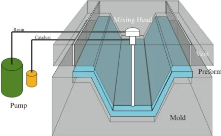
3.2.1 Resin Transfer Molding
Resin transfer molding is the most commonly used of the liquid molding techniques. It consists of a closed mould system, which produces components with excellent surface finishes and fiber volume ranging between 50-‐60%. It is perfect for production of high quality automotive and aerospace components. In this process the preform is place between a closed mould, and the resin is pumped into the mould at pressures ranging from 2-‐20 bar (see figure 3.1). The resin travels in the in-‐plane direction to the preform, this is a distinguishing
Figure 3.1: RTM
Variations to RTM include Vacuum assisted RTM (VARTM) where a vacuum is applied to aid in consolidation, air removal and increase the velocity of resin infiltration, and Structural Reaction Injection Molding (SRIM) where higher injection pressures are used to decrease production time. 1,2
3.2.2 Resin Film Infusion
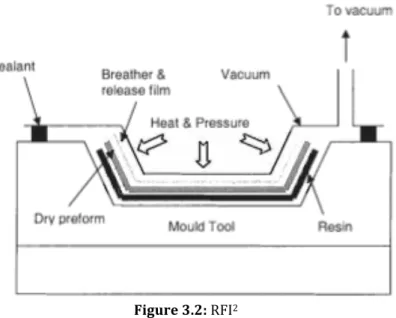
Resin Film Infusion (RFI) is an alternative to the RTM method. In RFI the resin is present in the form of a film instead of a liquid. The resin film is placed on the tool surface, over which the preform is placed. On top of the preform a release film (to allow for easy component removal) and breather material (in order to form a vacuum) are added. Everything is bagged, vacuumed and placed in an autoclave to be heated under pressure (see figure 3.2). The resin film melts and is sucked up into the preform through capillary action, thus being absorbed in the thickness direction. The pressure can be varied in order to compact the component to the desired fiber volume fraction. 1,2
Figure 3.2: RFI2
RFI has many advantages and disadvantages of RTM. The advantages of RFI consist of the relatively low tooling costs and the loss of the maximum injection length limitations. However, RFI has limitations in the thickness of the component. Therefore RFI is usually used with thinner larger components while RTM is suited for smaller thicker components. Another disadvantage of RFI is the relatively high costs of the resin film, which can cost up to two times the price of the pure resin, as well as their difficulty to handle. 1,2
3.2.3 SCRIMP
Seemann Composite Resin Infusion Process (SCRIMP) is a mixture of both the RTM and the RFI consolidation processes. SCRIMP uses a liquid resin from an external source, like with RTM, and impregnates the preform in the thickness direction, like with RFI. To achieve resin absorption in the thickness direction, a resin distribution medium is used. This medium allows the resin to flow quickly over the preform surface, spreading over the entire surface and then being absorbed in a similar fashion to RFI through the thickness of the component. The preparation is similar to RFI, with the layering of the components and sealing in a vacuum bag. The prepared setup is then placed under vacuum and the resin is sucked into the freeform through a resin inlet port. The vacuum created pressure gradient provides the driving force for resin infusion and no other injection equipment is needed. This process has an advantage in that tooling costs are cut similar to RFI, as well as cost reductions in the raw materials as in RTM. The limitations of thickness and maximum length are also overcome in this process. 1,2
3.3 Consolidation Equipment
sided mold or open mold is used. The most important consideration is the material used to produce the mold. This depends on cost and production volume. For low production volume, wood and plaster are generally used to make the mold due to the ease of mold production and low costs. However for large production volumes (10,000s) metals such as steel and aluminum are chosen. For high production volumes, it is more cost efficient to use metals due to their high durability the need for repair or replacement is greatly reduced. Also metals tend to produce higher quality surface finishes and allow for a wider range of processing temperatures.
3.3.2 Heating and Cooling
As with all the other equipment, the heating and cooling systems are dependent on the consolidation process. For RFI and SCRIMP, using an open mold, it is more cost effective to use an external heating sources, such as a convection oven, autoclave (figure 3.3) or other similar heating devices. The heating system selected will depend on component size, shape, required heating rate and curing temperature. Cooling is generally achieved through air-‐cooling.
2,4
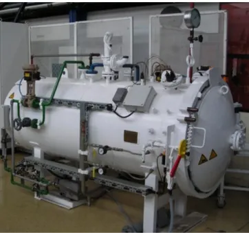
Figure 3.3: Autoclave for composite consolidation. Image provided by AAC research
For RTM heating using external sources becomes too expensive. Here it becomes more cost effective to use an integrated heating system. This system consists of a series of internal channels that allow for temperature controlled