In Supremae Dignitatis
· Universit`
a di Pisa
FACOLT `A DI INGEGNERIA
Dipartimento Di Sistemi Elettrici ed Automazione
Dependability Analysis of a Safety
Critical System:
The LHC Beam Dumping System at
CERN
Tesi di Dottorato di Ricerca in Automatica, Robotica
e Bioingegneria
Relatore:
Prof. Ing.
ALDO BALESTRINO
Co-relatore:
Dr. Ir.
JAN UYTHOVEN
Candidato:
Ing.
ROBERTO FILIPPINI
Anno Accademico 2005-2006
Abstract
This thesis presents the dependability study of the Beam Dumping System of the Large Hadron Collider (LHC), the high energy particle accelerator to be commissioned at CERN in summer 2007. There are two identical, independent LHC Beam Dumping Systems (LBDS), one per LHC beam, each consisting of a series of magnets that extract the particle beam from the LHC ring into the extraction line leading to the absorbing block. The consequences of a failure within the LBDS can be very severe. This risk is reduced by applying redundancy to the design of the most critical components and on-line surveillance that, in case of a detected failure, issues a safe operation abort, called false beam dump.
The system has been studied applying Failure Modes Effects and Criticality Analysis (FMECA) and reliability prediction. The system failure processes have been represented with a state transition diagram, governed by a Markov regener-ative stochastic process, and analysed for different operational scenarios for one year of operation. The analysis of the system results in a safety level ranked SIL4 in the IEC 61508 standard and 4 (± 2) expected false beam dumps generated per LBDS. These results will be validated through a three months reliability run. Several sensitivity analyses have been made providing additional evidence on the importance of the fault tolerant design features and the achieved trade-off between safety and availability.
The Beam Dumping System is part of the LHC machine Protection System for which a safety level SIL3 is required. A simplified model of the LHC Machine Pro-tection System (MPS), including the LBDS and other critical proPro-tection systems, has been analysed. Depending on the hazards (e.g. the fast beam losses being the most critical event in the LHC) and their coverage, the safety of the MPS has been calculated between SIL2 and SIL4 with about 40 (± 6) expected false dumps per year, which is the 10% of the machine fills. In the context of the MPS the LBDS is one of the safest systems and contributes to unavailability with an acceptable fraction of false dumps.
Acknowledgements
This thesis is the fruit of three years of work conducted at CERN in the AB/BT group. My first sincere thanks go to my supervisor Dr. Jan Uythoven. He has provided to me a continuous support during my stay at CERN, contributing in a significant way to the progress of my research with suggestions and ideas that have improved the thesis in its present version. I wish to thank Prof. Ing. Aldo Balestrino who has been my tutor at the Pisa University, for his expert guidance and the positive vision he has always had on my work. I owe gratitude to my colleagues of the AB/BT group at CERN, especially the group leader Dr. Volker Mertens and the project leader of the LHC Beam Dumping System, Dr. Brennan Goddard. I am pleased to thank Dr. Rudiger Schmidt for the precious opportunity that he gave me to apply my dependability studies also on the larger context of the LHC machine protection.
Among the other people, I wish to thank a colleague and friend of mine, Dr. Angelo Alessandri who has contributed to the revision of part of my thesis since the very early stages. A thanks goes also to my summer student David Huwe Jones, for the good work he performed during his short stay at CERN.
Finally, I wish to thank Prof. Fabio Uccelli, former employee of the INFN, who was at CERN in the sixty and Prof. Lorenzo Foa of the Scuola Normale of Pisa who encouraged me to have the unique experience of working at CERN.
Contents
Introduction xv
1 LHC Overview 1
1.1 The LHC Accelerator . . . 1
1.2 Accelerator Physics and Technology . . . 2
1.3 Safety Concerns and Machine Protection . . . 8
2 The LHC Beam Dumping System 13 2.1 The System Inventory . . . 13
2.1.1 Operational Modes . . . 14
2.2 The MKD System . . . 17
2.2.1 Power Triggers for the Kicker Magnets . . . 20
2.3 The MSD System . . . 22
2.4 The MKB System . . . 24
2.5 The Triggering System . . . 25
2.5.1 The VME Crate . . . 27
2.6 The Re-triggering System . . . 28
2.7 The Beam Energy Measurement System . . . 29
2.8 The Beam Energy Tracking System . . . 32
3 Introduction to Dependability 35 3.1 The System Dependability Attributes . . . 35
3.2 The Failure Process . . . 36
3.3 Dependability Modeling Techniques . . . 40 v
vi CONTENTS
3.3.1 Combinatorial-based Techniques . . . 41
3.3.2 State-based Modeling Techniques . . . 44
3.4 Design for Dependability . . . 45
3.4.1 Static Fault Tolerance . . . 46
3.4.2 Dynamic Fault Tolerance . . . 47
3.4.3 Hybrid Fault Tolerance . . . 48
3.4.4 The Role of Maintenance . . . 49
3.4.5 Comparison of Fault Tolerant Architectures . . . 50
3.5 Design for Safety . . . 53
3.5.1 Failsafe Protection Systems . . . 56
4 Probability Models 59 4.1 Generalities on Stochastic Processes . . . 59
4.2 Renewal Processes . . . 61
4.3 Markov Processes . . . 63
4.4 Markov Regenerative Processes . . . 66
4.4.1 Examples of Markov Regenerative Processes . . . 68
4.5 Markov Reward Processes . . . 69
4.6 The Solution of a Markov Process . . . 71
5 Dependability Modeling 75 5.1 Modeling of Elementary Failure Mechanisms . . . 75
5.2 Models for Reliability . . . 77
5.2.1 Model without Repair . . . 78
5.2.2 Model with Repairs on Demand . . . 80
5.2.3 Model with Periodic Inspections . . . 81
5.3 Models for Availability . . . 81
5.3.1 Model with Repair on Demand . . . 82
5.3.2 Model with Periodic Inspections . . . 83
5.4 Models for Safety . . . 83
5.4.1 Model for non Recoverable Safety . . . 84
CONTENTS vii
5.4.3 Other Models for Safety . . . 89
5.4.4 The Safety Trade-off . . . 91
6 Failure Modes Analysis of the LHC Beam Dumping System 95 6.1 The Modeling Framework . . . 95
6.2 The LBDS Failure Modes . . . 96
6.3 The MKD System Failure Modes . . . 99
6.3.1 The Power Triggers Failure Modes . . . 104
6.4 The MSD System Failure Modes . . . 105
6.5 The MKB System Failure Modes . . . 107
6.6 The Triggering System Failure Modes . . . 109
6.7 The Re-triggering System Failure Modes . . . 112
6.8 The BEMS Failure Modes . . . 113
6.9 The BETS Failure Modes . . . 115
7 Dependability Analysis of the LHC Beam Dumping System117 7.1 From FMECA to Failure Statistics . . . 117
7.2 Dependability Modeling of the LBDS . . . 123
7.2.1 The State Transition Diagrams . . . 123
7.2.2 Operational Scenarios . . . 128
7.3 The Operational Scenario 1 . . . 131
7.3.1 Dependability Analysis . . . 131
7.3.2 Criticality Analysis . . . 133
7.3.3 Sensitivity Analysis . . . 136
7.4 The Operational Scenario 2 . . . 139
7.4.1 Dependability Analysis . . . 139
7.5 The Operational Scenario 3 . . . 142
7.5.1 The Markov Regenerative Model . . . 142
7.5.2 Analysis of the Operational Scenario 3A . . . 144
7.5.3 Analysis of the Operational Scenario 3B . . . 148
7.6 Comparison Between the Different Operational Scenarios . . . 150
viii CONTENTS 8 Dependability Assessment of the Machine Protection
Sys-tem 157
8.1 A Simplified Machine Protection System . . . 157 8.2 A Dependability Model for the Simplified MPS . . . 158 8.3 Analysis of the Simplified MPS . . . 161
9 Conclusions 165
A Reliability Prediction of the LBDS Components 169 A.1 A Sample Case Study: The MKD System . . . 169 A.2 The LBDS Components Failure Rates . . . 173
List of Figures
1.1 The CERN complex . . . 2
1.2 LHC schematic. . . 4
1.3 Regular arc cell of the LHC . . . 7
1.4 The Machine Protection Systems along the LHC Ring . . . 10
1.5 The Machine Protection System beam permit loop. . . 11
2.1 LBDS essential layout . . . 15
2.2 The twisted ‘e’ beam shape profile at the TDE target . . . 15
2.3 The functional architecture of one MKD generator assembly. . 18
2.4 The beam deflection angles for the MKD and the MKB magnets 19 2.5 Functional architecture of the power trigger. . . 21
2.6 The functional architecture of the MSD system . . . 23
2.7 The functional architecture of one MKB generator. . . 25
2.8 The functional architecture of the triggering system. . . 26
2.9 The functional architecture of the re-triggering system. . . 29
2.10 The functional architecture of the BEMS. . . 31
2.11 The functional architecture of the BETS. . . 33
3.1 The bathtub curve of the hazard rate function. . . 38
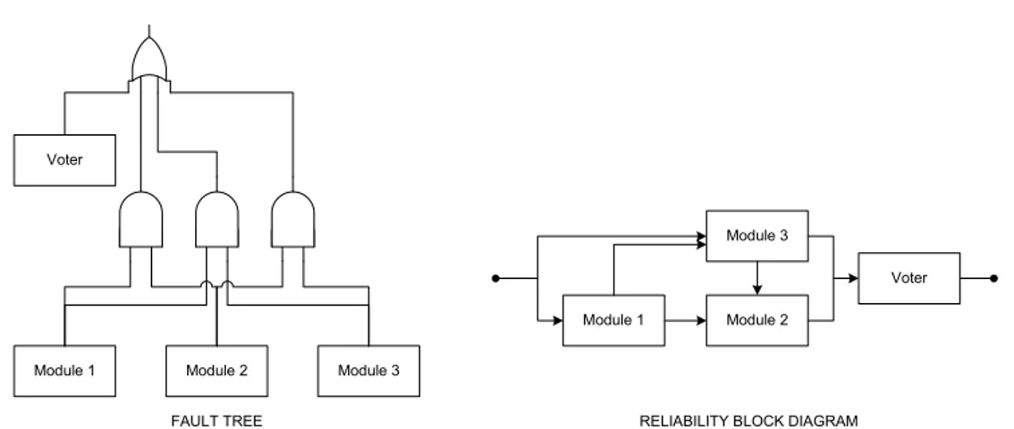
3.2 Fault tree and reliability block diagram of a Triple Modular Redundancy (TMR) . . . 43
3.3 Triple Modular Redundancy. . . 47
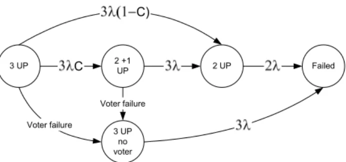
3.4 State transition diagram for the TMR . . . 47
3.5 State transition diagram of a TMR with stand-by spare . . . . 49 ix
x LIST OF FIGURES
3.6 Hybrid N-Modular Redundancy with M spares. . . 50
3.7 Hazard functions of fault tolerant architectures . . . 53
3.8 The state transition diagram for a failsafe TMR . . . 57
4.1 Renewal counting processes. . . 62
4.2 A realization of a Markov regenerative process. . . 67
5.1 Markov chain for modeling failure dependence. . . 76
5.2 Models of failure processes. . . 80
5.3 A safety model with failsafe shutdown. . . 85
5.4 A safety model with failsafe shutdown and repair. . . 88
5.5 A safety model with failsafe shutdown and periodic inspection. 89 5.6 Alternative models for safety. . . 90
5.7 A safety model for more protection systems. . . 91
6.1 Dependability modeling and analysis framework. . . 96
6.2 LBDS functional description. . . 97
7.1 The rates of the MKD system failure modes. . . 122
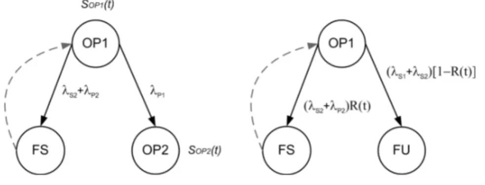
7.2 The state transition diagram during the mission . . . 124
7.3 The state transition diagram during checks. . . 124
7.4 Transition rates to the unsafe state X5 . . . 127
7.5 Transition rates to the safe state X5 . . . 127
7.6 A Petri net for missions and checks . . . 130
7.7 The state transition diagram generated from the Petri net. . . 130
7.8 The unsafety rate and unsafety of the LBDS . . . 132
7.9 Probability distribution of the number of false dumps . . . 133
7.10 Comparison of unsafety rate for two operational scenarios . . . 141
7.11 Unsafety upper and lower bound solutions . . . 145
7.12 Accuracy of the numerical solution . . . 145
7.13 Various Weibull probability distributions . . . 147
7.14 Probability density function of the dump requests . . . 149 7.15 Sensitivity of safety to the distribution of the dump requests . 151
INDEX xi 7.16 The 95% one side confidence interval for the MKD generator
branch failure rate. . . 154 8.1 The simplified state transition diagram of the MPS. . . 159 8.2 The reliability block diagram of the simplified MPS. . . 160 8.3 Sensitivity analysis of safety of the Machine Protection System 163 A.1 The primary capacitor of the MKD generator . . . 174 A.2 The compensation switch. . . 175 A.3 Primary capacitor assembly. . . 175 A.4 Compensation capacitors assembly of the overshoot1 circuit. . 176 A.5 MKD power supplies . . . 176 A.6 Magnet coil and transmission lines. . . 178
List of Tables
1.1 The LHC and beam main parameters . . . 3
2.1 Main LHC Beam Dumping System parameters. . . 16
2.2 Coverage of the erratic trigger events. . . 30
2.3 BETS coverage matrix . . . 33
3.1 Frequency categories. . . 54
3.2 Consequence categories. . . 55
3.3 Frequency x consequences = class of risk. . . 55
3.4 Safety Integrity Levels. . . 55
4.1 The solution techniques for Markov chains. . . 72
6.1 Failure modes of the LHC Beam Dumping System. . . 100
6.2 MKD system failure modes. . . 101
6.3 Logic operators. . . 101
6.4 Power trigger failure modes. . . 104
6.5 MSD system failure modes. . . 106
6.6 MKB system failure modes. . . 107
6.7 Triggering system failure modes. . . 110
6.8 Re-triggering system failure modes. . . 112
6.9 Beam Energy Acquisition failure modes. . . 113
6.10 BEMS failure modes. . . 114
6.11 BETS failure modes. . . 116 xiii
xiv LIST OF TABLES
7.1 Logic operators and probabilities. . . 118
7.2 The rates of the LBDS failure modes. . . 121
7.3 Expressions used in the definition of the state transition rates. 125 7.4 The transitions of the Petri net. . . 129
7.5 The operational scenarios. . . 131
7.6 Apportionment of unsafety to the LBDS components. . . 135
7.7 Apportionment of false dumps to the LBDS components. . . . 135
7.8 Apportionment of false dumps to the failure modes. . . 135
7.9 Sensitivity to fault tolerant design and surveillance. . . 137
7.10 Sensitivity to the failure rates. . . 138
7.11 Sensitivity to planned dump requests distribution . . . 147
7.12 Sensitivity to the beam induced dumps distribution . . . 149
7.13 Summary of the analysis of the operational scenarios. . . 152
8.1 The components of the simplified MPS. . . 157
8.2 Safety and number of false dumps for the MPS . . . 162
A.1 Failure rates and the apportionment of failure modes for the MKD components. . . 177
A.2 MKD system failure rates. . . 178
A.3 MKB system failure rates. . . 179
A.4 MSD system failure rates. . . 179
A.5 Power trigger failure rates. . . 180
A.6 Triggering system failure rates. . . 180
A.7 Retriggering system failure rates. . . 181
A.8 BETS failure rates. . . 181
A.9 BEMS failure rates. . . 181
Introduction
The Large Hadron Collider (LHC), approved by the CERN Council in December 1994, is planned to come into operation by the end of 2007. The accelerator occupies an approximately circular tunnel, 27 km in circumfer-ence and 3.8 m in diameter, located between 100 m and 150 m underground, crossing the Swiss-French border at the periphery of Geneva. The LHC will accelerate two counter-rotating beams of protons that are nuclei of hydrogen atoms [56, 57]. The two beams will collide at a centre of mass energy of 2 × 7 TeV, about 35 times the energy of the LEP [55], a previous accelerator at CERN, and 7 times the energy of the Fermilab Tevatron [64], which makes the LHC the world’s most powerful particle accelerator for high energies physics. The collisions will result in the scattering and disintegration of the nuclei and their constituents with the production of particles that will permit to investigate the matter on a sub-nuclear scale, searching for signatures of super-symmetry, dark matter and the origins of mass [56].
This thesis presents the analysis of the dependability of the LHC Beam Dumping System (LBDS). The LBDS performs the extraction of the high energy proton beam from the LHC ring, its dilution and steering through the dump tunnel and the safe deposition into an absorber block. Any failure leading to the unavailability of the LBDS during the operation is a severe safety concern for the LHC. The system has been designed in order to contain the residual risk of failure. A safety level of SIL3 of the IEC 61508 standard is demanded for the LHC Machine Protection System, of which the LBDS is an important component. The study follows some similar work on different
xvi Introduction equipment already done at CERN (e.g. the quench protection system [90] and the beam loss monitor system [37]). These studies describe the consequences of failures and give an estimate of their likelihood, which is the ultimate goal of the dependability assessment. They all apply FMECA (Failure Modes, Effects and Criticality Analysis) though they differ in the methodology for the analysis: the Monte Carlo simulation was applied in [90] while fault tree analysis was used in [37].
This study applies Markov processes and Markov regenerative stochas-tic processes to the modeling and analysis of dependability problems. This approach is demonstrated to be an elegant and mathematically exact way to describe the system failure processes together with the dependability at-tributes, as alternative to either a fault-tree or a Monte Carlo approach.
The work is organized as follows. Chapter 1 gives an overview of the LHC accelerator and some rudimentary information on accelerator physics and technology. The LBDS is described in Chapter 2. Chapter 3 introduces dependability terminology and design methods that apply to make a system resilient to failure and safe in particular. Chapter 4 describes the proba-bility models for modeling the dependaproba-bility, which are used in Chapter 5 for reliability, availability and safety applications. Chapter 6 outlines the FMECA analysis of the LBDS. In Chapter 7 the model of the LBDS failure processes is built and an analysis is performed for one year of operation and different operational scenarios, resulting in figures for safety and availability, which are completed by an additional sensitivity analysis of the main design parameters. Chapter 8 provides an overall estimate of the dependability for a simplified LHC machine protection system, including the LBDS and the most important protection systems. A summary of the results of the study and some final remarks are given in Chapter 9.
Chapter 1
LHC Overview
1.1
The LHC Accelerator
The LHC is the highest energy accelerator of a chain of accelerators, rang-ing from the particle production to the injection in the LHC rrang-ings where the beam is stored, accelerated and finally extracted at the end of the opera-tional cycle, see Figure 1.1. In each accelerator the beam energy is increased [56]. The protons p+ are a type of hadrons, which form a broad category of particles that includes also neutrons and in general all particles that build the nucleus of the atoms1. They are produced in the LINAC (LINear
ACcel-erator), packed in bunches during the acceleration process and transferred to the PS booster and further into the PS (Proton Synchrotron). From the PS they are transferred to the SPS accelerator (the Super Proton Synchrotron) where they are accelerated up to an energy of 450 GeV and subsequently injected into the LHC rings2. The final LHC proton beam, at nominal
inten-sity, will consist of 2808 (nb) bunches , each containing 1.15 × 10¹¹ protons
(Np) resulting in a total beam current of 0.584 A. The two beams are
acceler-ated to a beam energy of 7 TeV and can be kept circulating for hours at the ultra-relativistic velocity of 0.999999991 times the speed of light, completing
1The LHC will also accelerate ions but at less intensity than the proton beams. 2The nominal LHC filling requires 12 injections from the SPS for each LHC ring [57].
2 1. LHC Overview
Figure 1.1: The CERN complex [19]. a machine circumference of 26.7 km in 89 µs.
Beam collisions are foreseen at four interaction points in the heart of the main experiments: ALICE (A Large Ion Collider Experiment), ATLAS, CMS (Compact Muon Solenoid), and LHCb (LHC beauty experiment). At the ATLAS and CMS experiments, the beams are squeezed in transverse beam size to about 16 µm, which increases the chances of a collision among the individual particles of the two beams. Just to give an idea, the squeezing of 100,000 million protons (at nominal beam currents) per bunch down to 16 µm (1/5 the width of a human hair) at an interaction point results in around 20 collisions per crossing. The bunch spacing is 25 ns, so that one collision occurs every 25 ns. The LHC main parameters are listed in Table 1.1.
1.2
Accelerator Physics and Technology
The LHC is a synchrotron, which is a type of particle accelerator usually characterized by a quasi-circular vacuum chamber (i.e. the ring) in which the beam is circulating, surrounded by magnets. The ring is split in 8 oc-tants, separately powered and accessible from the surface through the access points, see Figure 1.2. One beam is injected at point 2, the other at point
1.2 Accelerator Physics and Technology 3
Quantity Value
Beam energy (E) 7.00 TeV
Beam current 0.584 A
Circumference 26.7 Km
Number of protons per bunch (Np) 1.15 × 10¹¹
Dipole field (B) 8.4 Tesla
Revolution frequency (frev) 11.24 kHz
Number of bunches per beam (nb) 2808
Proton (rest) mass (m0) 1.672 × 10⁻²⁷ kg
Normalized emittance (ǫn) 3.75 µm × rad
Proton charge (q) 1.602 × 10⁻¹⁹ Coulomb
Beta function at collision (β) 0.50 m
Luminosity (L) 1.0 × 1034 cm−2sec−1
Table 1.1: The LHC and beam main nominal parameters [56].
8. The extraction or beam dumping system is located at point 6. The Radio Frequency (RF) system, required to accelerate the beam, is placed at point 4 while the collimators (beam cleaning) are at points 3 and 7.
The LHC ring is occupied by magnets for steering and focusing the beam in order to keep a high energy and intensity beam circulating for the necessary length of the experiments. The most important magnets for the LHC are the dipole magnets and the quadrupole magnets.
The dipole magnets play a crucial role in the LHC as they determine the bending angle of the quasi circular orbit in the horizontal plane. The relation between bending angle and magnetic field of the dipole magnets is calculated with Lorenz’s law. The bending angle Θ is determined by the magnetic induction B, the relativistic mass m, the charge q, the velocity v of the particle and the length of the magnet l :
Θ = q × mvBl (1.1)
where m = √ m0
1−(v/c)2. At the top LHC beam energy of 7 TeV the required
magnetic induction is 8.4 T for 14.3 m long magnets, resulting in a bending angle of 0.0051 rad. This field requires a current of around 11,700 A in the
4 1. LHC Overview
Figure 1.2: LHC schematic.
superconducting dipole magnets for a total of 1232 of magnets that deviate the beam over 2π. The super-conducting magnets of the LHC work at a super-fluid helium temperature of 1.9 K. They have two apertures, one for each of the counter-rotating beams. In order to avoid undesired collisions with residual gas molecules, an ultra high vacuum of 1.33 × 10⁻¹⁰mbar (∼= 3
million molecules/cm3) is created in the beam pipes. Additional small orbit
correctors, shorts dipole magnets, are installed to correct the beam orbit in the horizontal and vertical planes.
The quadrupole magnets focus the beams in the transverse planes. A quadrupole magnet has four poles with alternating polarities, symmetrically arranged around the centre of the magnet. The resulting magnetic field lines follow a hyperbolic contour with the strength increasing proportionally to the distance from the centre. The magnet acts like a focusing lens in one plane, and a defocusing lens in the other plane. A global beam focusing in both planes is reached by alternating focusing and defocusing quadrupole
1.2 Accelerator Physics and Technology 5 magnets, called FODO lattice. The obtained transverse motion around the circular trajectory for a single particle is described by Hill’s equation.
d2z
s2 + K(s)z = 0 (1.2)
where z stands for either the horizontal x or vertical coordinate y and s is the longitudinal displacement along the reference orbit3. The focusing strength
K (s) is a function of s, K(s) = (q × g(s))/p, where g(s) = ∂By/∂x is the
gradient of the quadrupole magnet in the x plane and g(s) = −∂Bx/∂y
is the gradient in the y plane, p is the momentum and q is the charge of the particle. The solution of (1.2) is a residual harmonic oscillation called betatron oscillation:
x(s) =pǫβ(s)cos(φ(s) + φ0) (1.3)
where ǫ is the a constant called emittance4, which describes the beam quality,
β(s) is the beta-function, φ(s) + φ0 is the phase advance which together
describe the magnetic optics. The equation (1.2) is solved for the initial condition ǫ and φ0, which define the position of the particle in the phase space
x, dx/ds. Other quantities derived from (1.2) are the number of betatron oscillations per turn that is called the betatron tune Q, and the transverse beam size which is given by σx,y =√ǫβ.
The beam is accelerated by a longitudinal electric field from a resonant cavity, generated by the Radio Frequency (RF) system. The frequency of the cavity is set to a multiple of the beam revolution frequency. In the LHC, this frequency is 400 MHz, which corresponds to an oscillation period of 2.5 ns. This defines the stable phase for the bunches of particles, separated by 25 ns at the injection in the LHC and during the complete LHC operational cycle. All particles describe a longitudinal oscillation around the stable phase, called synchrotron oscillation (for the LHC around 21.4 Hz). The synchrotron
3This equation is only valid for particles without any energy deviation and large bending
radii.
4The emittance is related to the normalized emittance as quoted in Table 1.1 by ǫ n=
6 1. LHC Overview oscillation must not be confused with another phenomenon, the synchrotron radiation, which is related to the deflection of the high energy particles by the dipole bending magnets, giving rise to emission of light. The synchrotron radiation is mostly important for light particles like electrons and was a major effect for the LEP. Nevertheless, it will not be totally negligible for the LHC due to the high energy reached for the beams. The RF will compensate these losses.
Second order phenomena exist that affect the beam quality and require the addition of higher order multipole magnets. Sextupole magnets are placed close to the quadrupoles in the LHC in order to control the chro-maticity, a quantity that relates the Q tune spread to the momentum spread of the beam. The skew quadrupoles control the coupling between the two transverse planes. Other magnets like octupoles and decapoles are introduced in order to handle resonances and higher order effects. A more detailed de-scription of this extensive subject is beyond the scope of this thesis and is not treated here.
All magnets for steering and focusing the beam or compensating the higher order phenomena are arranged in a cell structure that repeats iden-tically along the arcs of the LHC ring, see Figure 1.3. Every three bending dipoles there is a quadrupole with orbit correctors positioned close to it.
Special types of magnets are used for the injection and the extraction of the two beams into and from the LHC ring respectively. These are the kicker magnets, which are pulsed, and the septum magnets, which work continuously. The extraction magnets are part of the beam dumping system. In this system there are 15 extraction fast pulsed kicker magnets, followed by 15 septum magnets and 10 dilution kicker magnets that guide the beam along 700 meters of the dump tunnel toward the graphite absorber block. The safety of the beam dumping system of the LHC is the main subject of this thesis. Details of its functioning and the design will be given in Chapter 2.
1.2 Accelerator Physics and Technology 7
Figure 1.3: Regular arc cell of the LHC [19].
luminosity. This is defined as the number of particles per square centimeter, per second crossing at the interaction point:
L = N
2 pnbfrev
2πσ2 (1.4)
Whereas in past and present colliders the luminosity culminates around L = 1032cm−2s−1, the LHC is designed to reach L = 1034cm−2s−1, two orders
of magnitude higher, see also Table 1.1. This gain in luminosity is not for free. When two bunches cross in the centre of a physics detector only a tiny fraction of the particles collide, giving about 20 collisions per crossing, and result in the wanted events. The large majority of the particles are deflected by the electromagnetic field of the opposing bunch without colliding. These deflections, which are stronger for denser bunches, accumulate turn after turn and may eventually lead to particles loss. This beam-beam effect was studied in previous colliders, where experience showed that one could not increase the bunch density beyond a certain value, the so called beam-beam limit, to preserve a sufficiently long beam lifetime. In order to reach the maximum luminosity the LHC has to operate as close as possible to this limit.
A collimation system, made of various blocks of different materials, is designed to catch and absorb any unstable particles before they can reach
8 1. LHC Overview the beam pipe wall and quench5 the superconducting magnets. This way
the beam losses are confined in well-shielded regions far from any supercon-ducting elements. Beam losses in the LHC ring are detected by the beam loss monitoring system or indirectly by the quench protection system of the superconducting magnets. Other instruments are also required, in particular the Beam Position Monitors (BPM) to measure the beam position.
1.3
Safety Concerns and Machine Protection
The studies on the safety of particle accelerators are a necessity for the accelerators with large stored beam energy for which the severity of failures are drastically amplified. In this respect, the LHC is going to be the most powerful particle accelerators both for the energy stored in the beam and the energy stored in its magnets6. The consequences of a failure in the LHC
are estimated in damage to costly superconducting magnets and radioactive contamination, resulting in many months or even years of downtime for the accelerator. For these reasons, the LHC project is demanded to comply with strict safety recommendations similar to those applied in nuclear power engineering7.
The safety in the LHC is assured by the LHC Machine Protection System MPS [56, 92]. The MPS checks continuously for the existence of safe condi-tions for the LHC, before entering operation and especially during operation when the beam is circulating. In case of detected failures in the machine or beam anomalies, the MPS issues a beam dump request and the operation is aborted. The unavailability of the MPS has potentially serious consequences [89], depending on the part of system which failed or is left without
protec-5The quench is the transition of the superconducting state to its normal state and
releases the magnetic energy stored in the magnets.
6The energy stored in the magnets is 11 GJ [56], equivalent to 2.8 tons of TNT. 7The timescale of failures developing in a nuclear power plant is longer than that in
the particle accelerators where a reaction time of milliseconds could not be sufficient to preserve the machine from the catastrophe.
1.3 Safety Concerns and Machine Protection 9 tion and exposed to an increased hazard. The overall MPS is required to be SIL3, that corresponds to a failure rate in the interval [10−8/h, 10−7/h] as
specified in the IEC 61508 standard [42]. The failsafe strategy of aborting the operation in case of any detected failure is expected to be determinant in the achievement of the required safety level for the LHC, as it will be explained in section 3.5. Nevertheless, none of the MPS components should disrupt the machine operation above a reasonable limit by creating physically unfounded dump requests or beam-inhibit signals. This is a further requirement which determines a trade-off between the safety and availability for the MPS.
The MPS consists of a large number of complex systems involved in the protection task of the LHC. Some of these systems are devoted to the beam surveillance (e.g. beam losses, beam position, etc.), others to the surveil-lance of the status of critical equipment (e.g. super conducting magnets, power converters, etc.). An inventory of these includes: the beam loss mon-itor system to detect beam losses, the beam dumping system for the beam extraction, the quench protection system that detects load change in the superconducting elements, the powering interlock controller that interlocks the powering of the superconducting magnets, the collimation systems, the RF system, the beam position monitors, the vacuum system and others (see Figure 1.4).
The core of the MPS is the Beam Interlocking System that consists of 16 Beam Interlock Controllers (two per sector) communicating via fiber optics to form the beam permit loop, see Figure 1.5. All machine protections systems are directly or indirectly connected to a Beam Interlock Controller (BIC) with their user permit signal. The beam permit loop is the result of a handshaking protocol (user permit ⇐⇒ beam permit) between the users and the local BIC. Each BIC receives the 10 MHz signal (i.e. the token) that is retransmitted to the neighbour BIC only if all local user’s permit signals are received, which means that they are functioning. If this holds for all 16 BICs, the token starts circulating and the beam can be injected in the machine. For reliability reasons, there are two loops per beam, four in total, with one token
10 1. LHC Overview
Figure 1.4: The Machine Protection Systems along the LHC Ring [56]. circulating in the clockwise direction and another anti-clockwise. Each BIC may cut the loops at any moment during operation in case at least one of the user permits has turned to false8, and a dump request is transmitted
to the LBDS. The timing response from the detected critical event to the transmission at the LBDS interface is estimated to be about 70 µs [13].
Among the systems that make part of the MPS, the LBDS has a the responsibility of completing the protective task with a safe beam dump. As every operation always terminates with a beam dump, this system is the one for which safety has to be certified largely SIL3 or even better. The analysis of dependability of a simplified MPS will be given later in Chapter 8.
8More in general, the set of the interlocked systems depends on the operational phase
of the LHC. The full set is necessary only for high energy and high intensity beam and, in the remaining period, a subset of the users can be masked.
1.3 Safety Concerns and Machine Protection 11
Beam Permit Loops
LBDS BIC 3/4 Dump trigger BIC 1/2 BIC 15/16 BIC 5/6 BIC 13/14 BIC 11/12 BIC 9/10 BIC 7/8 User's permit User's permit User's permit User's permit User's permit User's permit User's permit User's permit
Chapter 2
The LHC Beam Dumping
System
This chapter describe the functioning principles of the LHC Beam Dump-ing System and its components.
2.1
The System Inventory
The LHC Beam Dumping System (LBDS) has the role of extracting the beams on demand from the LHC rings and safely depositing them onto the absorbing block at the end of the dump channel. For each LHC beam the LBDS consists of the following components, see Figure 2.1:
• The MKD system is a series of 15 kicker magnet assemblies with their pulse generators that horizontally deflects the beam from the circulat-ing orbit onto the extraction trajectory.
• The Q4 superconducting quadrupole is part of the optical elements of the circulating LHC beam but also enhances the horizontal deflection given by the MKD system to the extracted beam by more than 30%. It has an individual power converter.
• The MSD system is a series of 15 septum magnets for the vertical 13
14 2. The LHC Beam Dumping System deflection. There are three types of MSD; the MSDA, MSDB and MSDC, which differ in septum thickness and their magnetic field. They are connected to a single power converter.
• The MKB system consists of a series of 10 kicker magnet assemblies and their pulse generators, arranged into 4 MKBH and 6 MKBV systems for the horizontal and vertical dilution of the beam respectively. Due to the dilution of the beam, the MKB magnets reduce the beam energy density when it arrives at the absorbing block.
• The TDE absorbing blocks are at the end of the beam dump lines. The extracted beam impacts onto the TDE graphite block stamping a char-acteristic ‘e’ twisted shape profile (15 × 25 cm), imposed by the MKB system, see Figure 2.2. This is important for avoiding any damage of the TDE due to overheating.
• The TCDS is a passive element that protects the MSD magnets from beam impact. The TCDQ and the TCS are passive elements that protect the Q4 and the downstream LHC from beam impact.
The system inventory also includes: FPGA based electronics to gener-ate the synchronized triggering of the kicker magnets; PLC to guarantee the beam energy tracking of the power converters in the system, general status surveillance and diagnostics. The vacuum system of the beam pipes, the nitrogen over-pressure for the TDE and the different types of beam instru-mentation are also part of the LBDS but are not shown in Figure 2.1. The main LBDS parameters are summarized in Table 2.1.
2.1.1
Operational Modes
Three different operational modes of the LBDS can be defined: the ready mode, the firing mode and the post-operational mode. The LBDS is required to be in the ready mode at any moment when there is beam in the LHC. The triggering system of the LBDS receives the revolution frequency from the RF
2.1 The System Inventory 15
Figure 2.1: LBDS essential layout (courtesy of M. Gyr).
Figure 2.2: The twisted ‘e’ beam shape profile at the TDE target (courtesy of B. Goddard).
16 2. The LHC Beam Dumping System
System N. items Length [m] H Bdl [Tm] Deflection [mrad]
MKD 15 22.5 0.25 0.240 Q4 1 3 0.08 0.090 MSD 15 67.5 Type A: 0.8 Type B: 0.99 Type C: 1.17 2.400 (total) MKBH 6 7.6 1.64 +/- 0.28 MKBV 4 7.2 1.077 +/- 0.28 TDE 1 8 - -Dump line - 975 -
-Table 2.1: Main LHC Beam Dumping System parameters.
system, which is phase-locked to the beam abort gap, a time interval of 3µs where the ring is deliberately left free of particles and corresponds to the rise time of the magnetic field of the extraction kicker magnets MKD. The beam energy is measured by the beam energy measurement system (BEMS) that translates the current measured at the power converters of the LHC main dipoles into a beam energy value, which is delivered to the MKD and MKB systems and applied as voltage settings of the local power converters. The voltage settings of the MSD and Q4 also track the beam energy, although they are generated in a different way, external to the LBDS.
As soon as a dump request is generated the system passes to the firing mode. The triggering system receives the dump request from the beam-interlocking controller BIC (see Chapter 8), which is converted into a trigger signal synchronously distributed to the MKD and MKB systems. As a result, the MKD kicker magnets will fire simultaneously and will all reach their nominal field in less than 3 µs. The nominal field is kept at least 90 µs, the time necessary for the removal of the entire beam from the ring. After the MKD the beam passes through the Q4 and the MSD magnets, reaching the MKB magnets for the dilution.
The system moves to the post operational mode after the beam dump. Currents and voltages from magnets generators, power switches, etc. are recorded and processed in post mortem diagnostics in order to check that
2.2 The MKD System 17 everything has functioned as expected. In particular, they make it possi-ble to discover faults that have either accumulated undetected during the operation, or occurred at the moment of the beam dump. If this check is passed successfully, the system is re-armed and the local beam permit signal is generated and sent to the Beam Interlocking System. In case of discovered anomalies during the post operational mode further investigation could be necessary, with a temporary stop of LHC operation.
2.2
The MKD System
The MKD system of the LBDS consists, per beam, of a series of 15 kicker magnet assemblies with their individual generator. The functional architecture of the MKD system is shown in Figure 2.3. Each kicker magnet is about 1.5 meter long and consists of a tape wound steel yoke with a one-turn winding at either side of the beam aperture, surrounded by a mechanical support frame. The beam aperture is delimited by a ceramic chamber that also acts as vacuum barrier with a vacuum of about 10−11 mbar. The magnet
is connected to its generator by 8 parallel high voltage low inductance coaxial cables. Each generator consists of two identical redundant branches in parallel, charged to a voltage proportional to the beam energy signal that is received from the BEMS, see section 2.7. The high intensity current pulse of around 20 kA is the result of the discharge of a primary capacitor, charged up to 30 kV (depending on the beam energy), through a solid-state switch1. Two
circuits compensate the overshoot, the first (OS1) charged at 350 V, and the second (OS2) beam energy tuned around 300 V. Both compensation circuits discharge through the same switch. All power switches receive the trigger command from the triggering system via two redundant power triggers. The capacitors are of the self-healing type that means that an internal short-circuits only leads to a small reduction of the total capacitance, which can be monitored. The magnet current pulse reaches a maximum of 18.5 kA for
18 2. The LHC Beam Dumping System C-OS1 A Trigger Line A,B Trigger C-OS1 B Comp. switch B C-OS2 B Power Trigger A Trigger A Power Trigger B Comp. switch A C-OS2 A Power supply Power supply Trigger B Trigger Trigger Line A, B Power settings 2 Switch A C-Primary A Switch B B C-Primary Power supply 2 Re-Trigger Line A,B 10 Re-triggering lines A,B BEMS BETS Re-Trigger Line A,B PRIMARY OS1 OS2 BEA BEI V. Divider MAGNET
Figure 2.3: The functional architecture of one MKD generator assembly. a 7 TeV beam, with less than 3 µs rise time followed by a period of at least 90 µs where the field varies by less than 7.5%. The expected beam deflection is shown in Figure 2.4.
Many failures of the MKD system are deemed catastrophic. The MKD system is designed fault tolerant and continuously surveyed in order to with-stand these failures up to a certain limit or generating a failsafe operation abort once they are detected. These features are listed below:
• Redundancy of the MKD systems. 14 out of 15 systems are still able to perform a proper beam extraction2.
• Dual branch generator. Each generator has two identical branches in parallel with an independent solid state switch in each branch. One branch may withstand the full current pulse in case of failure of the other.
2There exist few failure modes that overdo this redundancy. They are treated in section
2.2 The MKD System 19 -0.4 -0.3 -0.2 -0.1 0 0.1 0.2 0.3 0.4 0 20 40 60 80 MKBH MKBV MKD t [µs]
Figure 2.4: The beam deflection angles [mrad] for the MKD and the MKB(H/V) magnets (courtesy of J. Uythoven).
• Redundant triggering. Two independent power triggers drive the switches of both generator branches.
• Surveillance of erratic triggers. The re-triggering system moni-tors the erratic triggers in the MKD generamoni-tors by 10 current pick-ups (placed at different points in the circuit) per system. In case of a de-tected erratic trigger, all MKD (and MKB) systems will be triggered asynchronously with the beam abort gap.
• Surveillance of the beam energy tracking. The primary and over-shoot (OS2) capacitor voltage settings are monitored. The values are acquired by a local Beam Energy Acquisition (BEA) card and trans-mitted to the Beam Energy Interlocking (BEI) card where they are compared to the present beam energy. One BEA-BEI card per MKD magnet generator exists. A dump request is issued if the difference between the reference beam energy and the measured settings exceeds the 0.5%.
Many signals are recorded at the moment of the dump trigger like the currents in the power triggers, in the switches and at the magnets. Their analysis in post mortem diagnostics permits to discover failures that have accumulated silently in the system.
20 2. The LHC Beam Dumping System
2.2.1
Power Triggers for the Kicker Magnets
The power trigger receives the trigger signal from the triggering and the re-triggering systems (sections 2.5 and 2.6) and re-transmits this sig-nal, shaped and amplified, to the MKD or the MKB generator switches, see Figure 2.3. The system is housed in a dedicated VME crate, one per MKD system, and consists of two identical Power Trigger Modules (PTM) working in parallel, as shown in Figure 2.5. Each PTM consists of a primary driver that receives the signal from the triggering and re-triggering systems. The driver commands the power switch (three Insulated Gate Bipolar Transistors, IGBT, in series) for the discharge of a capacitor at a voltage that ranges be-tween 800 V and 3000 V, as calculated by the power trigger controller (PTC) on the basis of the present beam energy. A mono-stable circuit generates the resulting output pulse. For reliability reasons, a second redundant path ex-ists, which makes it possible that the trigger signal reaches the power switch even in case of failure of the primary driver3. A compensation driver
com-mands another power switch (IGBT) for the discharge of an internal capaci-tor, which lengthens the pulse for the activation of the compensation circuit of the MKD generator. The compensation driver is designed to fire only if the primary has already fired, avoiding the dangerous scenario where only the compensation pulse is generated. Independent powering exists for the Power Trigger Controller (PTC-PS), the PTM (PTM-PS) and the primary capacitor of the trigger module (HV-PS). The resulting trigger pulse has the duration of 3 µs with 200 ns rise time and 400 A peak current.
The failure of the power trigger may lead to catastrophic consequences especially when it results in an erratic trigger for the MKD system. Fault tolerance and surveillance make it possible to withstands failures or issue an operation abort in the case that the failure is detected:
• Dual branch trigger module. The trigger signal is generated in two independent modules. One module is able to withstand the failure of
3In this case, the current flowing through the second path will damage the switch and
2.2 The MKD System 21
Power Trigger Module PTM A
Power Trigger Module PTM B Power Trigger Controller PTC PTC PS HV PS PTM PS Profibus-Master Driver Primary Driver Compensation Power Switch Primary Power Switch Compensation Current pick-up PTM PS HV PS PTM PS PTM PS PTM Triggering/
Re-triggering Magnet switch
Triggering
Re-Triggering Redundant 2nd path
22 2. The LHC Beam Dumping System the other. As a resulting drawback the likelihood of erratic triggers is doubled.
• Surveillance of power supplies failure. The Power Trigger Con-troller (PTC) provides the continuous surveillance of the power supplies (+/-150V, 48V and 15V). The power supply of the primary capacitor within the Power Trigger Modules (PTM) is also monitored.
The input and output currents of the power triggers are monitored for post mortem diagnostics. They may reveal either a false contact or a missed trigger from an input line4.
2.3
The MSD System
The MSD system consists of a series of 15 septum magnets comprising five MSDA, five MSDB and five MSDC. The functional architecture is shown in Figure 2.6. Each magnet is about 4.5 meter long and consists of a laminated iron-dominated frame, built using a welded construction of two half-cores, the coil and the septum. One chamber exists for the circulating beam and one for the extracted beam, kept at a vacuum of 10−11 mbar and 10−8 mbar
respectively. One power converter supplies all magnets with a current that depends on the actual beam energy [9]. The nominal septum current for a 7 TeV beam is 880 A, resulting in an integrated magnetic field of 0.80 Tm in the MSDA, 1.0 Tm in the MSDB and 1.17 Tm in the MSDC magnet.
No failure of any magnet in the MSD can be tolerated and the conse-quences are severe. To reduce this risk, the system implements continuous surveillance:
• Surveillance of the beam energy tracking. The local BEI com-pares the measured current in the generator PC, which is identical to
4The perfect coverage of all failures is impossible. For instance, one major concern is
the fault of the clamping diodes in the input section that leaves the module unprotected from over voltages with an increased risk of breakdowns.
2.3 The MSD System 23
Figure 2.6: The functional architecture of the MSD system: the system (left) and one MSDC magnet (right).
the current in the magnets, to the theoretical value derived from the present beam energy. The dump request is generated and delivered to the BETS if a 0.5% error is detected (see section 2.8). This check is also effective for slow load changes that make the field change beyond the 0.5% tolerance5.
• Surveillance of fast magnet field decay. A short in a magnet coil or in the PC is expected to provoke a fast field drop in less than 1 ms that is covered by the Fast Magnet Current Change Monitor (FMCCM) [96].
• Surveillance of coil overheating. The septa magnets are water-cooled. In case of a cooling system failure any overheating is detected by thermo-switches (one per coil layer, 75 in total for the MSD system) and an alarm will be sent to the local PLC that generates a dump
5As the septa are continuously powered the survey of their current is a better guarantee
of their proper operation than the survey of the voltage of the pulsed magnets. Some of these failures are also caught by the PC internal surveillance, which is not included in the analysed system.
24 2. The LHC Beam Dumping System request and will subsequently switch off the PC.
Currents and voltages are collected for post mortem diagnostics in order to discover failures that have accumulated silently, as well as slow drifts in the electrical parameters that lead to a degraded magnet field.
2.4
The MKB System
The MKB system of the LBDS consists of 10 kicker magnets arranged into 4 MKBH, for the deflection in the horizontal plane, and 6 MKBV, for the deflection in the vertical plane. The magnet length is 1.9 m for the MKBH and 1.2 m for the MKBV. The functional architecture is shown in Figure 2.7. The system is mounted in a vacuum tank with a pressure of 10−6 mbar
and no vacuum chamber for the beam is required. Each magnet is connected to its generator by 10 parallel low inductance high voltage coaxial cables. Each generator is powered to a voltage proportional to the calculated beam energy and triggered by the triggering system. More in detail, the generator for the MKBH consists of an oscillating capacitor circuit CH (pre-charged up to 16.4 kV) that discharges through a solid-state switch6 (switch-H). The
resulting current pulse is an attenuated sinusoid, 25 kA of amplitude and 70 µs of period, which at its maximum causes a beam deflection of 0.278 mrad in the horizontal plane for the total of four MKBH magnets, see Figure 2.4. Similarly, the MKBV consists of one resonant capacitor circuit CV (pre-charged up to 22.3 kV) that discharges through a solid-state switch (switch-V). The resulting current pulse is an attenuated sinusoid, phase shifted by 90 degrees with respect to the MKBH pulse, which produces a beam deflection of 0.277 mrad in the vertical plane for the six magnets, see Figure 2.4.
The failure of the MKB system is severe only if all magnets are lost for the vertical or the horizontal dilution, which is a conservative definition. In all other cases, dilution of the beam energy is reduced but still acceptable,
6The solid-state switches are identical to those used in the MKD generators and receive
2.5 The Triggering System 25 Trigger Line A,B Switch-V Power Trigger Trigger A CV Power supply V Power settings Switch-H CH Power supply H BEMS BETS MKBH MKBV Trigger Line A,B Power Trigger Trigger Triggering system General surveillance General surveillance BEI BEA V. divider BEI BEA V. divider MAGNET MAGNET
Figure 2.7: The functional architecture of one MKB generator. resulting in possible overheating of the TDE block. Differently from the MKD system, the architecture of the generators is not redundant. There is only one power trigger instead of two and one branch instead of two per generator. For this reason, the system has continuous surveillance for the energy tracking failures with one BEI card per magnet generator, connected to the BETS. During operation, the currents at the local power triggers, the power switch and at the magnet are collected for post mortem diagnostics.
2.5
The Triggering System
The triggering system delivers the synchronized trigger signal to the power triggers of the kicker magnet generators [4, 16]. It consists of two independent VME (LinxOS) boards housed in one VME (64X) crate. Each board is connected to the local Beam Interlock Controller (BIC point 6, see Chapter 8) via an optical interface. Dump requests are received and stored into a buffer. The signal that drives the buffer is generated by an oscillator implemented in an FPGA, which keeps it tuned to the beam revolution fre-quency and locks the phase to the beam free gap. Once the dump request
26 2. The LHC Beam Dumping System
Figure 2.8: The functional architecture of the triggering system.
has been received, this is transmitted (synchronized) to an output trigger gate where it is shaped and amplified. A fan-out current transformer dis-tributes the output pulse to the power triggers of the MKD and MKB kicker magnets. For reliability reasons, a delayed (> 90µs) asynchronous trigger is also sent to the re-triggering system [17, 77]. The functional architecture of the triggering system is shown in Figure 2.8.
The failure of the triggering system is catastrophic only in case the trig-ger is not transmitted to all magnets (i.e. generation part failure) or it is transmitted to less than 14 MKD (i.e. fan-out distribution failure). The synchronization error is not critical due to the passive protection elements TCDQ, TCDS and TCS that minimize the consequences of a sweep of the beam over the Q4 and MSD magnets. However it is unwanted because of the likelihood of generating quenches of the superconducting magnets, and the increased risk of damage if, for example, the TCDQ is not in its correct po-sition. To reduce the likelihood of these failures, the system is fault tolerant
2.5 The Triggering System 27 and continuously surveyed.
• Redundancy in the trigger generation part. The trigger genera-tion is made of two redundant and identical modules so that one trigger generation failure can be tolerated.
• Redundancy in the trigger distribution. The trigger distribution consists of two independent paths for the synchronized trigger so that one distribution failure can be tolerated. The re-triggering lines still carry a delayed asynchronous trigger in case of the complete failure of the trigger distribution.
• Surveillance of synchronization failures. A crosschecking mecha-nism detects local and external synchronization errors with the beam free gap. Two internal synch-error bits are generated within the trig-gering system FPGA and shared between the trigger generators A and B. When a failure is detected, the status of one of these bits changes. The failed trigger generator must inhibit its dump request buffer and communicates its failure to the other trigger generator that issues a local dump trigger [77].
The output currents of the trigger generators and the trigger distribution lines, as well as the FPGA status, are recoded for post mortem diagnostics.
2.5.1
The VME Crate
The VME crates house the electronics boards of the triggering system and other LBDS electronics. The crate consists of one power supply module, one fan-tray module and the VME backplane designed to accept user boards that comply with the VME bus standard (6U × 160 mm). The power supply module receives 230 V AC main power from the UPS unit, which is internally converted into 15 V, 5 V and 3.3 V (DC). The system is cooled by a fan-tray consisting of three fans plus the fan control unit, which governs the rotation speed of each fan, depending on the air temperature. Internal surveillance
28 2. The LHC Beam Dumping System gives information on the status of the three converters and a dump request is generated in case a powering failure is detected. A beam dump request can also be programmed in case of failures of a fan. Customizing the VME crate could reduce the contribution to the system unavailability. For instance, one fan failure might be tolerated without generating a dump request and a second power supply module could be added in parallel to reduce the VME failure rate.
2.6
The Re-triggering System
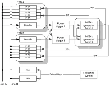
The re-triggering system is designed to catch erratic triggers in the MKD system and re-distribute them to all 15 MKD generators. If one MKD kicker fires, the other kickers will be triggered with a maximum delay of 700 ns for beam energies above 3 GeV/c. This action is not synchronized with the beam abort gap and produces beam losses to the septa and the arc aperture. Again, these losses are intercepted by the TCDS and TCDQ/TCS. The functional architecture is shown in Figure 2.9. The system consists of two independent re-triggering distribution lines A and B connected to the MKD power triggers via two Re-Triggering Boxes (RTB) [16, 17]. The re-triggering line also receives a trigger signal from the re-triggering system. Each re-triggering box picks up the current at different points in the primary and secondary circuit of the MKD pulse generators. It is connected to the power triggers A and B of the local MKD generators and to the re-triggering line. Once the erratic trigger reaches the RTB, it is distributed to the other RTB by a domino effect, using the energy stored at each stage.
The failure of the re-triggering system leaves the trigger event uncovered in all or part of the MKD systems. The re-triggering system is not surveyed7
but it implements redundancy in order to withstand failures at a reasonable extent.
7The re-triggering system is realized in passive components that make it unable to
2.7 The Beam Energy Measurement System 29
Figure 2.9: The functional architecture of the re-triggering system. • Redundancy in the current measurements. Every current in the
circuits is measured twice, and go to different RTBs, which guarantees a higher fault tolerance (see Table 2.2). For example, the primary capacitor current is picked up by one channel to the Re-Trigger Box A and one to the Re-Trigger Box B. This also assures the coverage of the erratic trigger at the power trigger, upstream the MKD generator branches.
• Double triggering lines. The re-triggering lines are doubled in order to withstand the failure of one of them.
At every beam dump the re-trigger signals (currents) are distributed to the kickers, which are analysed by post mortem.
2.7
The Beam Energy Measurement System
The Beam Energy Measurement System (BEMS) calculates the beam en-ergy that is distributed to the MKD and MKB systems in order to derive their settings [16]. The system receives the measured current of the LHC
30 2. The LHC Beam Dumping System
Input channel Source of erratic Power trigger MKD primary MKD OS1/2
Re-triggering line A INA1 Primary capacitor A A, B A, B INA2 Primary switch A A, B INA3 Comp. switch A A, B A INA4 Primary switch B A, B INA5 Comp. switch B A, B B Re-triggering line B INB1 Primary capacitor B A, B A, B INB2 Primary switch B A, B INB3 Comp. switch B A, B B INA4 Primary switch A A, B INA5 Comp. switch A A, B A
Table 2.2: Coverage of the erratic trigger events.
main dipole power converters at the points 4/5 and 7/8. To improve the reliability and for internal data validation, each current is measured twice by two Direct Current-Current Transformers (DCCT), connected to one Beam Energy Acquisition cards (BEA), as shown in Figure 2.10. The BEA acts as an Analogue to Digital Converter (ADC) between the power converter of the dipole magnets and the BEMS. A multiplexer alternates the input to the ADC module between four analogue values: two reference voltages and the two measurements from the DCCT of the same dipole magnet. The four values are converted in the ADC into 16-bit digital values. A noise filtering is applied by calculating the average of 16 samples for each of the 4 inputs. Re-sults are encoded and transmitted through a serial optical link8 to the BEM
card where they are decoded and treated separately. In this phase possible transmission, reception and timing errors will be detected. If no errors are detected, the four values are sent to two voters for the internal crosscheck: the input 1 is compared to the input 3 and the input 2 is compared to the input 4. The four values are then averaged and converted into a beam energy value, using a pre-loaded look up table saved into a flash-ROM and moved to two internal ROMs of the FPGA. The BEM sends the calculated beam energy to the the MKD and MKB magnets via an 8 bits bus where it is
2.7 The Beam Energy Measurement System 31
Figure 2.10: The functional architecture of the BEMS. finally translated into voltage settings.
The failure of the BEMS can be catastrophic due to the fact that it may deliver a wrong beam energy reference to the magnet power converters. In order to reduce this risk, the BEMS implements on-line surveillance over the the data processing for many input and output quantities. Part of the failures generated in the system are also detectable by the BETS.
• Redundancy in the data acquisition. The LHC dipole magnet currents used to determine the beam energy are measured at two dif-ferent sources at point 4/5 and 7/8. At each point the measurements are taken by two DCCTs.
• Surveillance of Transmission/Reception errors at the BEA-BEM interface. A dump request is issued in case the BEA-BEM has received a corrupt packet.
32 2. The LHC Beam Dumping System surveys the normal flux of operations. Timing errors with a resolution of 1 ms are caught and a dump request is generated.
• Surveillance of wrong values before conversion. A voting mech-anism checks that the values received from the two BEA cards are in agreement. A dump request is issued in case of any inconsistency. During operation, various signals are collected for post mortem diagnos-tics in order to discover failures that have accumulated silent in the system, FPGA included. There still remains subtle failures that are not detectable: if the current reading of all dipole PCs is erroneous and if the look-up tables have identical faults for the two BEMS. Those kinds of failures are called systematic or common mode type. Nevertheless, as they can only happen at the system start up, they are discovered during the dumping of the low inten-sity pilot beam in the operational mode, see section 2.1.1, with no resulting damage to the machine.
2.8
The Beam Energy Tracking System
The Beam Energy Tracking System (BETS) continuously checks that the settings in the LBDS power converters agree with the actual beam energy within a ±0.5% error tolerance [16]. The architecture is shown in Figure 2.11. The voltages of the MKD, MKB generators and the currents of the MSD and Q4 generators are acquired via BEA-BEI cards. In total, there are 27 BEA-BEI per beam, 15 for the MKD, 10 for the MKB, 1 for the MSD and 1 for the Q4. The BEI interfaces to the BEA with an optical receiver. The received values are first decoded then averaged and converted into beam energy values according to an internal look up table. As a final step, a voter compares the calculated energy value to the value received on the VME bus from another BEMS, which takes the measurements at the dipoles 5/6 and 6/7. A dump request is issued if the difference between any pair exceeds the preset ±0.5% threshold. The dump request mechanism is implemented in
2.8 The Beam Energy Tracking System 33
Figure 2.11: The functional architecture of the BETS.
Data acquisition channels BEMS MKD MKB MSD Q4
BEA-BEI 1 . . . 15 All set 1 per magnet
BEA-BEI 16 . . . 25 All set 1 per magnet
BEA-BEI 26 Yes Yes
BEA-BEI 27 Yes Yes
Table 2.3: BETS coverage matrix
the BETS with a current loop. Each BEI is able to cut the loop with the generation of the local dump request. This event is detected by the Beam Energy Controller (BEC) and transmitted to the triggering interface and the Beam Interlock Controller of the machine protection system. Like the RTS, the BETS is able to cover the energy tracking failures distributed in the LBDS, as shown in the coverage matrix of Table 2.3. The systems runs continuously self-surveillance over the whole data-processing, in the BEMS, in the BEI-BEA cards, and in the BEC.
A failure of the BETS leaves the LBDS uncovered with respect to all pow-ering failures or just a part of them, as it is shown in the coverage matrix of
34 2. The LHC Beam Dumping System Table 2.3. One BEI card per MKD and MKB generator assures the coverage of the energy tracking failures, one is for the MSD power converters while the failure in the BEMS is covered by the entire set of BEI cards. The BEC is responsible for the management of the dump requests from all BEI cards and represents a single point of failure for the system. In order to reduce the likelihood of these failures, the system verifies continuously the correct functioning of its parts. After a dump request, the BET system is checked with post mortem diagnostics and potential hidden failures are discovered.
Chapter 3
Introduction to Dependability
This chapter introduces to dependability engineering with a special at-tention to the architectures used for safety critical applications.
3.1
The System Dependability Attributes
Dependability is the measure for the quality of service in time given by the system. It encompasses the notions of availability, reliability, safety, maintainability and other more specialized attributes. In [53] dependability is defined ‘the ability of the system to deliver a service that can be justifiably trusted’ but other definitions are given by international standards authorities like ISO. Definitions of some dependability attributes are:
• Availability: the readiness for correct service. • Reliability: the continuity of correct service.
• Safety: absence of catastrophic consequences in case of failure. • Maintainability: the ability to undergo modifications and repairs. Availability distinguishes from reliability for the possibility of withstand-ing more service outages durwithstand-ing the system lifetime, just one outage bewithstand-ing unacceptable for a reliable system. Safety distinguishes from availability and
36 3. Introduction to Dependability reliability for the consequence of the service outage, which is ranked accord-ing to a severity level. Maintainability is the measure of the repair process including fault diagnosis, localization and isolation plus repair or replacement [2]. The dependability attributes can be also combined with other quantities (e.g. costs, quality of service, etc.) into indexes of performance, classified in literature under the term performability [88].
3.2
The Failure Process
The system failure is the final pathology of the failures of its compo-nents and their propagation. Its description is based on the fault-error-failure model, also called the ‘chain of threats’ [3]. Faults occurring at physical level are activated by patterns that can be reproducible (i.e. hard faults) or not (i.e. soft faults). The reproducible faults are also called permanent faults and move the component into a persistent faulty state. Faults are called transient if they happen under certain conditions that are difficult to repro-duce and predict. Failures are called random if they occur due to progressive degradation (hardware), or systematic (hardware and software) if they are in-troduced during the system life cycle [46]. Faults can develop independently but there may exist causes that provoke them simultaneously, generating a common mode failure, which is the most undesired event for the system. A detailed classification of faults and failures can be found in [53] and [73].
The dynamics of failures are intrinsically complex to analyse because of their random nature and the dimension of the failure space, often larger than the space of admissible states. A qualitative analysis, consisting of the classification the system failure modes, is necessary before looking at their likelihood through a quantitative analysis.
A qualitative analysis enumerates all failure mechanisms in the system and their consequences. Failure Modes and Effects Analysis (FMEA) or Failure Modes Effects and Criticalities Analysis (FMECA), if criticality (C) is also a concern, are systematic techniques for qualitative failure analysis [39,
![Figure 1.1: The CERN complex [19]. a machine circumference of 26.7 km in 89 µs.](https://thumb-eu.123doks.com/thumbv2/123dokorg/7247617.80378/20.892.226.646.193.467/figure-cern-complex-machine-circumference-km-µs.webp)