A Reference
Architecture
for the Component
Factory
VICTOR R. BASILI and GIANLUIGI CALDIERA University of Maryland and
GIOVANNI CANTONE
University’ di Napoli
Software reuse can be achieved through an organization that focuses on utilization of life cycle products from previous developments. The component factory is both an example of tlhe more general concepts of experience and domain factory and an organizational unit worth being considered independently. The critical features of such an organization are flexibility and continuous improvement. In order to achieve these features we can represent the architecture of the factory at different levels of abstraction and define a reference architecture from which specific architectures can be derived by instantiation. A reference architecture is an implementa-tion and organizaimplementa-tion independent representation of the component factory and its environment. The paper outlines this reference architecture, discusses the instantiation process, and presents some examples of specific architectures by comparing them in the framework of the reference model.
Categories and Subject Descriptors: D.2.9 [Software Engineering]: Management:, D.2.M
[Software Engineering]: Miscellaneous–rewa61e software; 1<.6.3 [Management of Computi-ng and Information Systems]: Software Management —software development
General Terms: Economics, Design, Management, Measurement
Additional Key Words and Phrases: Component factory, experience factory, reference architec-ture, reusability
1. INTRODUCTION
1.1 Background
The issue of productivity and quality is becoming critical for the sclftware industry at its current level of maturity. Software projects are requested to do more with less resources: deliver required systems faster, reduce
Research for this study was supported in part by NASA grant NSG-5123, by ONR grant
NOO014-87-K-O037 and by Italian CNR grant 89.00052.69.
Authors’ addresses: V. R. Basili and G. Caldiera, Institute for Advanced Computer Studies, Department of Computer Science, University of Maryland, College Park, Maryland G. Cantone, Dipartmento di Informatica e Sistemistica, University’ di Napoli, Naples, Italy.
Permission to copy without fee all or part of this material is granted provided that the copies are not made or distributed for direct commercial advantage, the ACM copyright notice and the title of the publication and its date appear, and notice is given that copying is by permission of the Association for Computing Machinery, To copy otherwise, or to republish, requires a fee and/or specific permission.
@ 1992 ACM 1049 -331 X/92/O100-053 $01.50
54 . V. R Baslli et al.
turnaround time in maintenance, increase performance reliability and secu-rity of systems. With this in mind, significant changes in the way software is produced today are needed. A straightforward solution to the problem of increasing quality and productivity is summarized in three goals: improve the effectiveness of the process, reduce the amount of rework, and reuse life-cycle products.
The production of software using reusable components is a significant step forward for all three of those goals. Use of preexisting well designed, tested, and documented elements as building blocks of programs will amplify the programming capabilities, reduce the amount of work needed on new pro-grams and systems, and achieve a better overall control over the production process and the quality of its products.
The possibility of assembling programs and systems from modular software units “classified by precision, robustness, time-space performance, size limits, and binding time of parameters” [151 has been suggested from the beginnings of software engineering. Howeverj such an approach has never acquired real momentum in industrial environments and software projects, despite the large amount of informal reuse already there.
Reuse is a simple concept: use the same thing more than once. But as far as software is concerned, it is sometimes difficult to define what is an object by itself, in isolation from its context [12]. Software objects may be programs, parts of programs, specifications, requirements, architectures, test cases and plans, all related to each other. Reuse of each software object implies the concurrent reuse of the other objects associated with it. This means we need to reuse more than code. Software objects and their relationships incorporate a large amount of experience from past development activities: it is the reuse of this experience that needs to be fully incorporated into the production process of software and that makes it possible to reuse software objects [4]. Problems in achieving higher levels of reuse are the inability to package experience in a readily available way, to recognize which experience is appropriate for reuse, and to integrate reuse activities into the software development process. Reuse is assumed to take place totally within the context of the project development. This is difficult because the project focus is the delivery of the system; packaging of reusable experience can be, at best, a secondary focus of the project. Besides, project personnel are not always in the best position to recognize which pieces of experience are appropriate for other projects. Finally, existing process models are not de-fined to support and to take advantage of reuse, much less to create reusable experience. They tend to be rigidly deterministic where, clearly, multiple process models are necessary for reusing experience and creating packaged experience for reuse.
1.2 Approach
In order to practice reuse effectively, an organization is needed whose main focus is to make reuse easy and effective. This implies a significant cultural change in the software industry, from a project-based frame of mind centered on the ideas and experience of project designers, to an organization-wide one, ACMTransactions on Software Engmeermg and Methodology, Vol. 1, No 1, January 1992
A Reference Architecture for the Component Factory . 55
where a portion of those ideas and experience becomes a permanent corporate asset, independent from the people who originate it. This cultural change will probably happen slowly, and a way to facilitate this change is to provide an organization that is flexible enough to accept this evolution. Two charac-teristics will typify such an organization:
—Flexibility. The organization must be able to change its configuration without a negative impact on its performance, thereby incrementally gain-ing control over the main factors affecting production.
— Continuous improvement (the Japanese “kaizen”). The organization must be able to learn from its own experience and to evolve towards higher levels of quality by building competencies and reusing them.
This paper presents some ideas on how to design the production of software using reusable compcments. In particular, we show the effectiveness of a representation of the cwganization with different levels of abstraction in order to achieve the desired flexibility. This leads us to the concept of a reference architecture that provides a representation of the organization as a CO1[ection of interacting parts, each one independent of thle way the others perform their task. In this framework, methods and tools can be changed inside each one of those independent “development islands,” like implementations in an object-oriented development, without the need for a change in the other ones. We outline a possible reference architecture and illustrate it with some examples.
After having automated other organizations’ business and production, today the software indlustry is facing the problem of a substantial automation of its activities. Without mechanically translating concepts that are perti -nent to very different production environments, Flexible Manufacturing systems combine many desirable features: modular architecture, integration of heterogeneous methods and tools, configuration and reconfiguration capa-bilities, and wide automation under human control. Flexible manufacturing comes of age in the software industry through the definition of integrated software engineering environments, if they are based on the concepts of flexibility and continuous improvement that we have mentioned earlier.
The next two secticms of this paper present an organizational framework designed to make reuse happen in the most effective manner. Sections 4 and 5 discuss the representation that we propose for this framework, which uses different levels of abstraction in order to obtain a flexible and evolutionary organizational design. Section 6 outlines our methodology for deriving a particular environment from the general one, and Section 7 illustrates this derivation with some theoretical and actual examples.
2. A REUSE-ORIENTED ORGANIZATION
In order to address the problems of reuse in a comprehensive way, Basili has proposed an organizational framework that separates the project-specific activities from the reuse packaging activities, with process models for sup-porting each of the activities [2]. The framework clefines two separate organi-zations: a project organization and an experience factory.
56 . V R. Basin et al
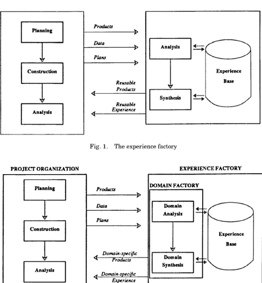
One organization is project oriented. Its goal is to deliver the systems required by the customer. It is called the project organization. The other organization, called experience factory, has the role of monitoring and analyz-ing project developments, developing and packaging experience for reuse in the form of knowledge, processes, tools and products, and supplying it to the project organization upon request.
Each project organization can choose its process model, based upon the characteristics of the project, taking advantage of prior experience with the various process models provided by the experience factory. It can access information about prior system requirements and solutions, effective meth-ods and tools, and even available system components. Based upon access to this prior experience, the project can choose and tailor the best possible processes, methods, and tools. It can reuse prior products tailored to its needs.
The experience factory, conceptually represented in Figure 1, is a logical andlor physical organization that supports project development by analyzing and synthesizing all kinds of experience, acting as a repository for such experience, and supplying that experience to various projects on demand. There are a variety of forms for packaged experience. There are, for instance,
(A) Reusable products
—reusable products of the life cycle (i. e., the Ada package that creates and updates B-trees);
—equations defining the relationship between variables (e. g., Effort = a* Sizeb);
—models and algorithms specifying processes, methods, and techniques (e. g., an SADT diagram defining Design Inspections with the reading technique as a variable dependent upon the focus and the reader perspective).
(B) Reusable experience
— charts of data (e. g., Pareto chart of classes of software defects);
—management curves (e. g., product size growth over time with confidence levels);
—specific lessons learned associated with project types, phases, and activities (e.g., in code inspections, reading by stepwise abstraction is most effective for finding interface faults).
From this brief discussion we see that the organization of the experience factory can be divided into several suborganizations, each dedicated to identi-fying, collecting, organizing, providing, and maintaining a particular kind of experience.
A first level of subdivision of the experience factory can be based on the application domain [16]: for each different domain we have a different do-main factory, conceptually represented in Figure 2, whose purpose is to define the process for producing applications within the domain, to implement the environment needed to support that process, and to monitor and improve that environment and process. Examples of domains are satellite ground support ACM TransactIons on Software Engineering and Methodology, Vol. 1, No 1, January 1992
A Reference Architecture for the Component Factory . 57
PROJE~ ORGANIZATION EXPERIENCEFA~ORY
u
PianningJ
T
Constructkm m Analysis PROJECYORGANIZATIONP
Planning +77
ConstructionEl
AnaJysls Praincu Plaas > Renwble ~ Reiuabie Experience <Fig. 1. The experience factory
--=---+ Plalu Donwin-specjlc a Pmdncls < Domzin.specifiErprricnc. EXPERIENCEFACTORY — )OMAINIFACTORY
7J~
Oanwin3
/---\ Analysis —=----’ Experience Base r m OOnnaln synthesis ~/Fig, 2. The domain factory,
software, information management— software for insurance companies, some classes of C 3 Systems, and so on. The experience manipulated by the domain factory is the definition of an application domain and the experience relative to engineering within that specific domain [8].
A further subdivision of the experience factory, that is the object of the discussion in this paper, is the development and packaging of sc)ftware components. This function is performed by an organization we call the component factory, conceptually represented in Figure 3, which supplies software components to projects upon demand and creates and maintains a repository of those components for future use. The experience manipulated by
58 . V, R. Basili et al PROJE~ ORGANIZATION m 1 J +
7?
Comdrwtionm
Ccwnponenls a Maids < EXPERIENCEFACTORY MPONENTFACTORYFig, 3, The component factory
the component factory is the programming and application experience as it is embodied in requirements, specifications, designs, programs, and associated documentation. The software component produced and manipulated by the component factory is a collection of artifacts that provide the project organiza-tion with everything needed to integrate it in an application system and to provide life-cycle support for this system.
The separation of project organization and (experience, domain, or compo-nent) factory is not as simple as it appears in our diagrams. Having one organization that designs and integrates only, and another that develops and packages only, is an ideal picture that can present itself in many different variations. For instance, in many cases, some development will be performed in the project organization according to its needs. Therefore, the flows of data and products across the boundary are different from the ones we have shown in the figures. One of the aims of this paper is to deal with this complexity, providing a rigorous framework for the representation of problems and solutions.
We focus on the concept of component factory, both as an example of the more general concept of experience factory and as an organizational unit worth being considered independently. On one hand, the component factory will be the framework used to define and discuss various organizational structures via our concept of reference architecture, which is applicable as well to the more general frameworks of domain and experience factory. On the other hand, the discussion will give us better insight into the role of the component factory as a milestone on the roadway to an industrialization of software development.
3. THE COMPONENT FACTORY
The concept of component factory is an extension and a redefinition of the concept of software factory, as it has evolved from the original meaning of integrated environment to the one of flexible software manufacturing [10]. ACMTransactIons on Software Engineering and Methodology, Vol. 1, No 1, January 1992
A Reference Architecture for the Component Factory . 59
The major difference is that, while the software factory is thought of as an independent unit producing code and using an integrated production environ-ment, the component factory handles every kind of code-related information and experience. The component factory is defined as a part of the experience factory, and therefore it is recognized that its potential benefits can be fully exploited only within this framework.
As noted earlier, a software component is an,y product in the software life-cycle, such as the following:
– Code components: objects implemented in some compilable, interpretable, or executable language. This includes programs, subprograms, program fragments, macros, simple classes and objects. Requirements can adso be considered as code components if they are specified using some formal representation; otherwise, they are textual objects and fall into the last class of this list.
—Designs: objects representing function, structure, and interfaces of software components (and cc)llections) written in a language that can be formal, semiformal, graphic, or natural. This includes structured design specifica-tions, interface specifications, functional specifications, and logical schemata. In some cases designs are code components themselves.
– Collections of code component or designs: objects obtained by aggregation of several functionally homogeneous code components or designs. This in-cludes the libraries (mathematical, statistical, graphic), the collect ions of packages of Ada-like languages, the composite classes of object-oriented languages, the architectures of structured design techniques.
—Documents: textual objects written in natural language with figures, ta-bles, and formulas to communicate information in some organized way. This includes requirements documents, standards and policy documents, recommendations, lessons-learned documents, reports from specific studies and analyses. Hypertext objects can, in many cases, be considered in this class.
The software component produced and maintained in the component fac-tory is the reusable software component (RSC); it is a collection made of a software component packaged with everything thi~t is necessary to reuse and maintain it in the future. This means very different things in different contexts, but it should include at least the code of the component, its functional specification, its context (i.e., borrowing the term from the Ada language, the list of the software components that are in some way associated with it), a full set of test cases, a classification according to a certain taxonomy and a reuser’s manual [9].
The project organization uses reusable software components to integrate them into the programs and systems that have been designed previously. Being closer to the customer/user and more aware of its needs, the project organization is responsible for the development and the deployment of the end product.
The capability of the component factory to make reuse happen in an efficient and reliable way is a critical element for the successful application
60 . V. R Basili et al
of the reuse technology. The catalog of available components much therefore be rich, in order to reduce the chances of development from scratch, and components must be easy to find.
There are three major groups of activities associated with the production of software through reusable software components
Use reusable software components. When the project organization needs a component described by a certain specification, the catalog of available components is searched:
—if a ready-to-integrate component that matches the specification is found, the project organization uses it;
—if a component that needs some adaptation in order to match the specification is found, the project organization uses it after the needed modifications have been applied to the component;
—if either no component is found that matches the specification or the needed adaptation is too large to be considered a simple modification of a preexisting component, the component is ordered.
Develop and maintain reusable software components. A reusable software component enters into the production process because it has been recog-nized as useful from a preliminary analysis of the application domains associated with the project organizations [1], or, because it was needed, it has been deemed “reusable,” and was not available.
Once the need for some component has been recognized or the compo-nent has been ordered, there are three ways for the component to enter into the production process:
(1) by direct development either from scratch or from preexisting generic elementary processes [13];
(2) by direct procurement from an external source (an external reposi-tory, a vendor) [17];
(3) by extraction and adaptation from existing programs and systems [9].
In whatever way the reusable component has entered into the produc-tion process, it is adapted for further reuse by enhancement or general-ization of its functions and structure, by fusion with other similar components, or by tailoring to expected needs. It is maintained to satisfy the evolving needs of the applications as identified by domain analysis and to guarantee its correctness.
Planning and economic analysis for reuse are part of this group of activities. The component factory can optimize its performance by under-standing the future needs of the project organizations and developing in advance the needed artifacts, and by selecting the most economic way of coping with those needs.
Collect and package experience from activities. The activities of project organizations and component factory are recorded and transformed
A Reference Architecture for the Component Factory . 61
into reusable process packages. This means they are packaged in units that are understandable by everybody interested in using them, either independent or explicitly declared and packaged with their dependencies, and retrievable using some kind of search procedure.
The experience is formalized and translated into a model, Different kinds of models are produced in order to rep-resent the knowledge that the project organizations and the component factory have of products, process, resources, and quality factors;
—product models representing the observable characteristics of the soft-ware components through measures;
—process models representing the observable characteristics of the pro-duction process, its phases and states, and the measures that allow its control;
—resource and cost models representing the amount of resources allo-cated to, or estimated for, a set of activities and their distribution; and —lessons-learned models representing the knowledge acquired from
for-mer projects and experiments.
The ability to anticipate future needs is critical to the efficient implemen-tation of a reuse oriented paradigm and to the wor”k of the component factory, in order to satisfy the requests coming from the project organization as soon as possible. Also critical is the ability to learn from past activities and to improve the service w bile providing it. Therefore, crucial tc~ the component factory are creation and improvement of the models, based on a methodology to systematize the learning and reuse process and to make it more efficient. Models are defined and constantly improved through use–learning from past experience and translating this knowledge into changes to the model. The methodology that systematizes the learning and improving processes is the improvement Paradigm [2] outlined in the following steps (Figure 4):
1. Plan
1.1 Characterize the activity and the environment in order to identify and isolate the relevant experience.
1.2 Set the goals and refine them into a measurable form (this is done using the GQM approach).
1.3 Choose the execution process model, the supporting methods andi tools, and the associated control measurement.
2. Execute the process, control it, using the chosen measurement, and pro-vide real-time feedback to the project organization.
3. Analyze the results and compare them with the goals defined in the planning phase.
4. Synthesize
4.1 Consolidate the results into updates to the formal models and to their relationships.
62 . V R. Basili et al / PACKAGE SNrOREOSABLEUNITS
(
UPDATE MODELS SYNTHESIZE \ ANALYZE COMPARE WITHGom‘“’””s”\
CHARACTEFUZE \ SmGOALS PLAN \ ~OOSE PROCESS ANo KEAslJREMENr EXECUTE / EXECUIT PROCESS / CONTROL BY MEASUREMENTFig. 4. The improvement paradigm
4.2 Package the updated models into reusable units and store them for future reuse.
The improvement paradigm is based upon the notion that improving the software process and product requires the continual accumulation of evalu-ated experience in a form that can be effectively understood and modified into a repository of integrated models which can be accessed and modified to meet current needs. It is derived from the scientific method to supply environments such as software projects, in which mathematical formalization and organizational institutionalization play a prominent role, with an incre-mental learning methodology. It plays, in software environments, a role similar to the Shewart –Deming cycle [11], plan/do/check/act in manufactur-ing environments.
4. LEVELS OF REPRESENTATION OF A COMPONENT FACTORY
The experience factory and its specialization, the component factory, are necessarily very general organizational elements. Every environment has its characteristics and pursues its goals by means different from every other one. Therefore, we need different levels of abstraction in the description of the architecture of a component factory in order to introduce at the right level ACMTransactions on Software Engineering and Methodology, Vol 1, No 1, January 1992
A Reference Architecture for the Component I=actory . 63
0
ArchiteduralAgents0
o
00
REFERENCELEVELo
--=yuALLE”L
BoJcdo
\
Organirdlon Component0--/
?’Y
o
0“-0
CTjF)
~=:ONLE”L
ffj’f
If
if
(EQ
———
E!)
(E9
DqartmentA DepartmentB ~=== DepartmentC
‘-—
Fig. 5. The levels of abstraction
the specificity of each environment. The allocation of a function to an organizational unit is a first distinction; the actual implementation of some functions, for instance through automated tools, is another distinction, How-ever, these choices are only variations of the paradigm of the component factory that can be captured using different levels of abstraction in represent-ing the framework of the factory.
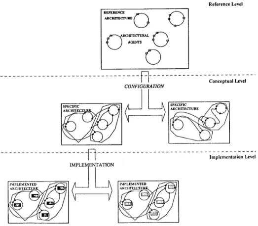
In this section we briefly discuss the levels of abstraction that we want to use to represent the architecture of a component fhctory (Figure 5):
Reference level. At this first and most abstract level we represent the building blocks, and the rules to connect them, that can be used to represent an architecture. This is not the description of a component factory but a modeling language for it. The basic bui].ding blocks are called arch itecturaz agents and represent the active eh?!mlentS perfclrming
64 . V. R. Baslli et al,
tasks within the component factory or interacting with it. They exchange among each other software objects and messages.
Example. In the last section, we discussed the activities associated with the production of software through reusable components and decided that a reusable component may enter into the production process by direct development, by procurement from an external source, or by extraction and adaptation from preexisting software. Each one of these possibilities becomes a function that can be assigned to an active element of the reference level:
— an agent decides which reusable components are needed, —an agent develops reusable components,
an agent provides external off-the-shelf reusable components, —an agent extracts and reengineers reusable components, and —an agent manages the internal repository of reusable components.
These agents have potential connections with other agents: for instance, the agent that develops reusable components is able to receive specifica-tions from another agent, and the agent that decides which reusable components are needed is able to provide these specifications, but the actual connection is not specified at the reference level.
Conceptual level. At this level, we represent the interface of the architec-tural agents and the flows of data and control among them, and specify who communicates with whom, what is done in the component factory and what in the project organization. The boundary of the component factory, i.e., the line that separates it from the project organization, is defined at this level, based on needs and characteristics of an organiza-tion, and can change with them.
Example. In a possible conceptual architecture, the agent that designs systems and orders components, located in the project organization, is connected with an agent that develops reusable components, located in the component factory. Specifications and designs are exchanged be-tween these two agents.
In another conceptual architecture, the agent that designs systems and orders components, still located in the project organization, communi-cates with an agent that coordinates the activities of component develop-ment and adaptation in the component factory. It is this agent that communicates with an agent that develops reusable components, ex-changing specifications and designs with it.
Implementation level. At this level, we define the actual implementation, both technical and organizational, of the agents and of their connections specified at conceptual level. We assign to them process and product models, synchronization and communication rules, appropriate performers (people or computers), and specify other implementation details. The
A Reference Architecture for the Component f’actory . 65
mapping of the agents over the departments of the organization is included in the specifications provided at this level of abstraction.
Example. The organization is partitioned into the following departrnents:
— system analysis and deployment, —system development,
—quality assurance and control, and —software engineering laboratory.
In a possible organizational choice, the functions of component design are allocated to system development, and the functions of system integration are divided between system analysis and deployment amd quality assur-ance and control. The software engineering laboratory analyzes the production process, provides the models to control the activities, and improves those models through experience. The component factory in-cludes system development and software engineering laboratory. The process model for design is the iterative enhancement model: it starts from a group of kernel functions and delivers it to system analysis and deployment, and then expands this group of functions in order to cover the whole set of requirements in successive makes of the system. lDevel -opment is done in Ada using a language-sensitive structured editor and an interactive debugger.
Each one of these levels of abstraction can be divided inko sublevels by different operations applied to the agents or their connections:
–functional decomposition: an agent is decomposed in a top-down fashion into more specific agents; and
— connection decomposition or specialization: a connection between agents is decomposed into different pipelines, or the object types are refined, or synchronization rules are defined in greater detail;
The drawing of the boundary separating project organization and compo-nent factory at the conceptual level is motivated by the need for defining a formal interface between the two organizations, more formal than the one between the agents that lay inside each one. We can, for instance, imagine the boundary as a validation and verification checkpoint for tlhe products that go across it. More generally, we can look at the pair project organiza-tion/component factor as at a user/server pair that can be used for quality measurement and improvement.
The next section discusses in some detail the reference level and then. deals with the problem of the instantiation of a generic architecture into a slpecific one.
5. THE REFERENCE ARCHITECTURE
While the reference level describes a generic architecture, the conceptual and implementation levels describe a specific one at different levels of detail. In
66 . V. R. Bash et al.
order to obtain a specific architecture, we can either design it from scratch or obtain it as an instantiation of a generic architecture. The problem with the architecture designed from scratch is that it does not give enough assurances that it will be able to evolve to match the needs of the organization or to follow its evolution: designing from scratch is often focused on the needs and goals of the present organization and does not take its evolution into account.
The instantiation of a generic architecture is instead a technique that leads to more flexible architectures, because the adaptability is already in the abstraction. The specific architecture can be obtained from the abstract one through instantiation. It can be modified by altering the instantiation with-out changing the generic architecture, which is explicitly parametric and reusable. Besides, a generic architecture is a common denominator for com-paring and evaluating different specific instantiations. It allows us to choose the architecture that is best suited for a particular organization.
The reference level provides this generic architecture. A reference architec-ture for the component factory is a description of the component factory in terms of its parts, structure, and purpose, defining which parts might cooper-ate and to what purpose [7]. The interacting parts of the reference architec-ture are kept free from unnecessary linkages between each other in order to keep the concerns separate and to leave this to the instantiation process. The genericity of the reference of the reference model is represented by the many possible ways of connecting parts at the conceptual level for a specific architecture, and the many ways to map them into the implementation level. The elements of the reference architecture, the architectural agents, are the components of the factory production process. we do not make any assumption about the way they are implemented: they can be a person, a group of people, or a computer-based system. The reference architecture specifies only their tasks and the necessary communication paths, leaving to particular instantiation implementation and the specification of their na-ture. We can look at the agents as islands in the component factory, whose nature and implementation can be changed according to the needs and the improvement goals of the organization, independent of other agents. This allows us to implement the tasks of an agent today with a group of people, and tomorrow with a computer-based system, introducing changes that do not impact the whole organization.
Reference architecture can be associated with different life-cycle models. A previous paper has discussed the relationship between the “waterfall” model and component factory [91, showing how it is possible to split that life cycle into two separate ones. It can be shown that other life-cycle models, such as the iterative enhancements model, the spiral model, and explorative proto-typing models, can be used in this context without substantial changes to the reference architecture. However, we do not deal with this issue here because it is outside the scope of this paper.
From our discussion in Section 3 of the activities associated with the production of software through reusable components, we can derive a set of functional requirements for the architectural agents operating in the
A Reference Architecture for the Component Factory . 67
nent factory or interacting with it:
–Receive the specifications of a system and produce its design, taking into account the information about existing reusable software components made available by the component factory. These functions specify the role of the designer agent.
—Build the specified system according to the design, using the reusable components made available by the component factory, and perforlm the system test in order to verify the conformance of the deve~ol?ed system with the requirements. These functions specify the role of the integrator agent. —Choose how to fulfill a given request for a reusable software component,
based on the specification of the component and on the information about existing reusable software components already available in the component factory. The choice between development from scratch and adaptatior[ of an existing component is probably done according to a model of cost and time effectiveness, i.e., whether it is worth modifying an existing component or the modification would be so substantial that it is more convenient to develop a new component. These functions specify the role of the shopfloor coordinator agent.
–Develop a reusable software component according to a given specification. The development includes the design of the component, its implementation, and verification. These functions specify the role of the developer agent. –Modify a reusable software component that is “close enough” to the one
described by a given specification. The modification activities include the analysis of the impact of a certain adaptation, its implementation, and verification. These functions specify the role of the adapter agent.
–Produce and update reusable components based on domain knowledge, extract reusable components from existing code, and generalize already existing reusable components into other reusable components. The main difference between these functions and the development ones is that these are asynchronous with respect to the production process in the project organization. These functions specify the role of the component manipula-tor agent.
—Develop formal models analyzing the experience develope~d in the compo-nent factory and in its interfaces with the project organizations. The experience that is collected and processed has different levels of formaliza-tion, according to the incremental perspective provided by the imlprove -ment paradigm. It starts with very simple models that are improved in a continuous way in order to fit better in the actual environment of the component factory. These functions specify the role of th(e experience mod-eler agent.
–Manage the collection of objects and information that is used by the component factory to store experience and products derived. from its activi -ties (experience base). In particular, this function includes the manage-ment of the repository of reusable software components, which is a ~subset
68 . V R. Basili et al
of the experience base. Every agent, while performing its tasks, accesses the experience base either to use its contents or to record a log of its activity. The access control, the manipulation of objects and the search strategy to answer a request are the main experience base management functions. These functions specify the role of the Experience Base Manager agent.
–Supply commercial or public domain off-the-shelf reusable components that satisfy the specifications developed by the organization. This function specifies the role of an External Repository Management agent.
This list of agents represent a complete set of architectural agents that cover all the activities of the component factory and of the project organiza -tion. However, we could have defined the agents differently. For example, the reference level can be decomposed into several sublevels, and the set of agents in the reference architecture presented here is one of these levels. Agents can be composed into larger ones or decomposed into more specific ones in a way that is very similar to the functional decomposition used in structured analysis. For instance, the designer agent can be merged with the shopfloor coordinator, obtaining an agent that specifies not only the compo-nents that are needed but also the way to obtain them. Or, the designer agent can be decomposed into a system designer agent performing the preliminary design of the system and also into the software designer agent performing the critical design.
It is also possible to expand the scope of the analysis, for instance, by introducing the collection and analysis of requirements into the picture and by specifying the agent that performs these functions in the reference architecture.
Besides a set of agents, the reference architecture contains a set of archi-tectural rules that specify how the architectural agents can be configured and connected in the specific architectures derived from a reference architecture.
One set of rules deals with the presence and replication of the agents. The agents in component factory can be unique or replicated: in the former case only one instance of the agent can be active, in the latter many instances of the agent are possibly active at the same time. For example, there might be two designer agents that share the service provided by one adapter agent.
Another set of rules deals with the connections between agents. The agents communicate with each other exchanging objects and experience at different levels of formalization, and cooperating towards the completion of certain tasks. This communication is realized through communication ports. A port is specified when we know what kind of objects can travel through it. For instance, the component manipulator agent has a port through which it receives and returns reusable software components. There are data ports and control ports: the port through which the designer agent receives the require-ments for the system is a data port; the port through which it receives the process model to design the system is a control port. A port bundles several channels: each one is an elementary access point specifying the kinds of objects traveling through it and their direction. For instance, the port through ACM Transactions on Software Engineering and Methodology, Vol. 1, No. 1, January 1992
A Reference Architecture for the Component Factory . 69
which the designer communicates, say with the shopfloor coordinator, has two channels: an output channel to send component specifications and an input channel to receive the requested reusable software components.
Ports can be mandatory, i.e., always presented on the agent in one or more instances, or optional, i.e., possibly absent in certain implementations of the agent. For instance, the developer agent always has a port through which it receives the specifications of the components it must develop and a port through which it returns the components it develops; these are mandatory ports. On the other hand, the developer might or might not have a port to receive external off-the-shelf reusable components to be used in the development of the requested components. From the point of view of the reference architecture, we do not make this choice, leaving it to the specific architecture.
We can represent our reference architecture using an Ada-like language in which the agents are task types that encompass port types in the wa,y Ada task types encompass entries [6]. This allows us to use the distinction between specification and body of the task type to defer the implementation of the agent to the specific architecture, and also to use Ada generics to represent certain abstractions that are specified at the conceptual level. In this representation, the architectural rules are declarative ~statements, incor-porated in the definition of the agent to which they are applied.
The specification language for the reference architecture is complemented by a configuration language whose purpose is to represent the choices made to instantiate the reference architecture into a specific conceptual architec-ture: presence and number of agents, presence and number of port~$, and connection of the ports. The implementation of the agents is specified by another language, the implementation language, which assigns a task body to each task type.
6. INSTANTIATION OF THE REFERENCE ARCHITECTURE
Reference architecture has been defined as a collection of architectural agents and rules supported by an experience base managed by an agent. Some freedom in this collection is eliminated by choices made when the architecture is instantiated at the different levels of abstraction.
(A) Choices at the reference level;
(a) Activities that are part of the software development process. In defining these activities one chooses the set of process models that are either currently used or will be used by the organization and breaks them down into activities that can be perfcwmed by someone or some machine. The granularity level of this decomposition is such that activity interfaces can be specified without specifying implemen-tation details.
(b) Clustering of activities into agents. One chooses activities that have strong bindings and deal with products at the same “level” of detail, and groups them into architectural agents.
70 . V. R. Basili et al.
(B) Choices at the conceptual level:
(a) Boundary between component factory and project organization. In making this choice one tries to optimize reuse by incorporating more functions into the component factory on the one hand, and to optimize customer service, on the other hand, by concentration of the appropri-ate activities in the project organization.
(b) Presence of agents, number of agents of each type, fusion of several agents. This choice is about communication complexity: a large num-ber of agents increases the complexity and the overhead due to communication, a small number of agents produces bottlenecks that would affect the whole organization.
(c) Presence of ports and number of ports. As in case (b), this choice deals with communication complexity: a large number of ports in-creases the complexity of the activities of a single agent but reduces the impact of possible bottlenecks.
(d) Interconnection of ports between different agents. This choice is about distribution of control: concentrating the control in a small group of agents makes planning easier, but serializes many activities that could otherwise be performed concurrently.
(C) Choices at the implementation level:
(a) Distribution of the agents over organizational units. This choice deals with the optimization of the already existing organization units and the smooth evolution to factory concepts. It takes into account the available resources and the historical roles of those units.
(b) Implementation of the functions of the agents (the task bodies). In choosing algorithms, procedures, methods and tools, one tries to achieve an organizational and technical profile that is correct, effi-cient, and best suited to the overall mission by dealing with the available resources and technology.
Therefore, in order to design a specific component factory, we need to instantiate the reference architecture by an instantiation process based on the levels of abstraction introduced earlier (Figure 6). This instantiation process is embedded in the methodological framework of the improvement paradigm now applied to the specific architecture. The four steps of the paradigm, introduced previously in a different context, become, in this con-text, the following:
1. Plan component factory: the desired instantiation is designed on the basis of characteristics of the organization and on the goals to be achieved. 1.1 Characterize the activities and the environment of the current
organi-zation: production process, products, formal and informal models cur-rently in use, software tools and standards.
1.2 Set goals and priorities for the introduction of the component factory and for its separation from the project organization: productivity, customer satisfaction, product maintenance and environment stabil-ity. The goals can be refined into questions and metrics that will be used to control the production of the component factory.
A Reference Architecture for the Component Factory . 71 ReferenceLevel
D
::::.*
(>
‘Cy==’-o
o
----
----
---
--—---
---
-—
--
fl
---
---ConceptualLevel CONFIGURATION ---r-L---- --- ---”. .
II
A
IMPLE E ATION lmpkmmtatfionLevelFig. 6. Instantiations of the reference architecture.
1.3 Instantiate the reference architecture into a particular component factory architecture and define the associated measurement environ-ment. Instantiation process A. A.1 A.2 A.3 B. Configuration of level) Definition of the the architecture. activities of the
(reference level +conceptual
organization and mapping of t“hose activities into specific architectu ral agents.
Identification of the boundary ofa specific factoryby specifying which agent is in the project organization and which is in the component factory.
Definition of the conceptual representation of thespecificcompo -nent factory by specifying the agents and connecting their ports using the configuration language.
Implementation of the architecture. (conceptual level -implementation level)
72 . V. R Basdi et al
B. 1 Specification of the mapping between the agents and their func-tions and the departments of the organization, and of the respon-sibilities for production control.
B.2 Definition of the implementation representation of the specific component factory by mapping agents and functions over specific units (e. g., people, automated or semiautomated tools), and speci-fying algorithms, protocols, and process models.
2. Produce components for the project organizations and load products and information into the experience base.
2.1 Execute the production process using the particular architecture that has been defined,
2.2 Control the process while executing by using the measurement envi-ronment that has been defined.
3. Analyze the results, after a preestablished period of time, assessing the level of achievement of the goals that were behind the introduction of the component factory.
4. Synthesize the results
4.1 Consolidate the results of the analysis into plans for new products, models, measures (etc.), or for updates for the existing ones
4.2 Package the new and updated products, models and measures into reusable units and store them for future reuse;
4.3 Modify the instantiation of the particular architecture and the meas-urement environment associated with it.
The crucial point of the process is the possibility, offered by the reference architecture, of modifying the particular architecture without modifying the interfaces between its building blocks. The modular structure allows configu-ration and reconfiguration of the processes as required by an efficient and realistic implementation of an optimizing paradigm. The evolution of the conceptual level and sublevels is more difficult because it has impact on the implementation level, but the explicit definition of the interface types, which is part of the reference architecture, offers a certain freedom in the evolution, even at the conceptual level. Changes in the automation and organizational choices definitely have a lower impact, if they are applied to the implementa-tion level, leaving the conceptual level unchanged.
7 EXAMPLES OF COMPONENT FACTORY ARCHITECTURES
7.1 Clustered and Detached Architectures
In the following examples we present different approaches to the problem of software reuse. We assume we are dealing with an organization that has already made the choice of software reuse and, therefore, has some kind of process model for doing so. This assumption is not very restrictive because, at least in an informal way, reuse happens in every software project.
A Reference Architecture for the Component Factory . 73
In order to illustrate the concepts of reference architecture and instantia-tion, we can present two different conceptual architectures for the component factory. The two architectures differ in the different roles they assign to the designer agent:
— in the first architecture, the designer coordinates all software development activities from the side of the project organization, we call it “clustered” architecture;
— in the second architecture, the development activities are concentrated in the component factory under the control of the shopfloor coordinator agent, we call it a “detached” architecture.
In a clustered component factory architecture (Figure 7a), every develop-ment takes lplace in the project organization, and the role of the component factory is to process and provide existing reusable software components. The agents are assigned in the following way.
Project Organization Component Factory
Designer/Integrator/ Component manipulator
Shopfloor coordinator Experience modeler
Developer Experience base manager
Adapter
In a detached component factory architecture (Figure 7b), no development takes place in the project organization, but only design and integration. The project organization develops its design of the system based on the informa-tion existing in the experience base and requests from the component factory all necessary developments. It then integrates the components received from the component factory according to the design. The agents are assigned in the following way:
Project Organization Component Factory
Designer Shopfloor coordinator
Integrator Developer
Adapter
Compone-nt manipulator Experience modeler Experience base manager
The activities of the agents that form the kernel of the component factory (component manipulator, experience modeler, experience base manager) do not change in the two instantiations. However, the role of the component factory in the detached architecture is much more relevant because it encom-passes activities that are both synchronous and asynchronous with the project organization.
An evaluation of the two instantiations can be performed using the GQM approach [51. After setting the goals of the evaluation by focusing on charac-teristics such as performance, functionality, and evolutionary nature, from
74 . V R. Basdl et al.
Lo
EXPESUENCJ3BASE
Fig. 7(a) The clustered architecture.
the viewpoint of the technical management of the organization, it is possible to derive questions and metrics that allow us to collect data to perform the comparison. The GQM is a rigorous approach to the problem of comparing two different architectures. If we want to stay at an intuitive level, the following remarks can be made:
–Performance: The level of productivity and serviceability of the project organization/component factory system.
In the clustered architecture, the project organization develops the compo-nents that are not available; if therefore it has enough resources, it probably performs faster because there is less communication overhead and more pressure for delivery. On the other hand, the components developed in the framework of a project are more context dependent, and this puts more load on the component factory, and in particular on the component manipulator.
In the detached architecture, there is more emphasis on developing gen-eral-purpose components in order to serve more efficiently several project organizations—planning is easier and the optimization of resources is more
A Reference Architecture for the Component Factory . 75
Fig. 7(b). The detached architecture.
effective. On the other hand, there are more chances for bottlenecks and periods of inactivity, due to a lack of requests from the projects, that affect the overall performance of the organization.
—Functionality: The conformance to the operating characteristics of an orga-nization producing software using reusable components.
In the clustered architecture, all functions are implemented, but the most critical ones are concentrated on the designer /integrator /shop floor coordi-nator. Thus the errors and operating failures of this agent can affect the functionality of the whole organization.
In the detached architecture, the high modularity of functions reduces the impact of errors and failures of one agent but increases the possibility of communication errors.
—Evolutionary nature
The clustered architecture is much closer to the way software is currently implemented, and therefore its impact on the organization would be less drastic.
The detached architecture provides the component factory with additional possibilities for adaptation and configuration, making cor~tinuous improve-ment easier and less expensive.
76 . V. R, Basili et al.
The detached architecture is probably better suited for environments where the practice of reuse is somewhat formalized and mature. An organization that is just starting should probably instantiate its component factory using the clustered architecture and then, when it reaches a sufficient level of maturity and improvement with this architecture, start implementing the detached architecture to continue the improvement. The improvement paradigm, as applied to the component factory in the last section, provides a methodology for a step-by-step approach to this implementation. In this way the organization takes advantage of the flexibility and evolutionary nature of this approach, which are among the primary benefits of reasoning in terms of instantiations of a reference architecture.
7.2 The Toshiba Software Factory
A further illustration of the concepts of reference architecture and instantia-tion comes from the analysis of a real case study.
One of the most significant accomplishments in the attempt to make software development into an industrial process is represented by the experi-ence of Toshiba Corp, in establishing, in 1977, the Fuchu Software Factory to produce application programs for industrial process control systems [14]. In
1985, the factory employed 2,300 people and shipped software at a monthly rate of 7.2 million EASL1 per month.
The Toshiba accomplishments are due, first of all, to the emphasis set by
the Toshiba management on teamwork and to its commitment to high
performance and quality. The continuous analysis and improvement of the software process are other elements of strength in the Toshiba (and, in general, in the Japanese) experience. Since there is no improvement that is not based on reuse of prior experience, the process is designed to achieve a high level of reusability (Figure 8).
Projects design, implement, and test the application systems reusing parts that are found in a reusable software items database. Just to give an idea of the size of an application system developed by a project, we have an average size of four million EASL, but there are projects that go up to 21 million EASL. The parts are made available by a parts manufacturing department, based on the requirements specified by a software parts steering committee made up of project people and of parts manufacturing people. Statistics on alteration and utilization of parts are processed and maintained by a parts manufacturing department.
The conceptual architecture of the Fuchu software factory (Figure 9) presents the replication of some agents.
—Project Organization
Shopfloor coordinator. This agent performs the functions of the software parts steering committee. It is very much project oriented, but some of its functions, such as planning for reuse, can be identified with some functions
1EASL: Equivalent Assembler Source Line of code.
A Reference Architecture for the Component Factory . 77 I PROJRCTXXXf I + ‘EpARmm PARTS MANUFACTURING ,
1-* msIGNEu PROGRAMMER
S4WIWAREPARTSSTEERINGCOMM137’EE
~~
>(jyj
~
-Oo{j
D E E L G 1 RS1 1 v DATABASE s E T R @z@~:tw . ratwn otlce Stalus–-1
1
RequiremtL/
P.R-m DESIGNER L I +$
—
PARTS — CERITFICATION ISFig. 8. The Toshiba Fuchu software factory
of the experience modeler in the reference architecture–– we can therefore position it at the border between project organization and component factory.
Designer 1.. This agent designs the application system and the components that have been deemed project specific by the coordinator.
Developer 1. This agent develops the software components specified by designer 1.
Integrator. This agent assembles the system using the components received from developer 1 and from the component factory, according to the design provided by designer 1, and verifies its conformance with the require-ments.
— Component Factory
Designer 2. This agent designs the components that have been deemed reusable by the coordinator.
Developer 2. This agent develops the software components specified by designer 2.
78 . V. R. Bash et al.
%==
Fig, 9, The Toshiba software factory architecture
Component adapter and manipulator. This agent can be identified with the parts manufacturing department that adapts and supplies parts under request and, based on the statistics on the utilization of the software parts contained in the database, modifies and improves those parts.
Experience base manager. This agent is in charge of the management of the parts center and, in particular, of access to the reusable software items database.
A function that is not explicitly implemented in this architecture is the experience modeling function, even though the factory uses state-of-the-art techniques to manage its projects. The absence of formal modeling experience is probably one of the causes for which (according to data reported by Matsumoto) the major factor affecting productivity is the reuse of code (52. l%), while improvement of processes, techniques, and tools have a less significant impact.
8. FUTURE DIRECTIONS
Flexible automation of software development combined with reuse of life cycle products seems the most promising program to solve many of the quality and productivity problems of the software industry. It is very likely ACM TransactIons on Software Engineering and Methodology, Vol. 1, No 1, January 1992
A Reference Architecture for the Component I’actory . 79
that in the coming years we will see a wide and deep change in the industry, similar to the one that took place in manufacturing through the introduction of CIM (Computer Integrated Manufacturing).
The abstraction levels and the reference architecture presented in this paper are aimed at providing a framework to make both automation and reuse possible. The major benefits of this approach are the following:
— a better understanding of reuse and of the requirements that need to be satisfied in order to implement it in a cost-effective way;
—the possibility of using a quantitative approach, based on models and metrics, in order to analyze the tradeoffs in design associated with use of the component factory;
—formalization of the analysis of the software development process and organization, with a consequent enhancement of the possibilities for au-tomation; and,
—the definition and use of an evolutionary model for the improvement of a reuse-oriented production processes.
Two of the major problems the software industry is facing today, when using automated production-support tools like CASE (application generators, analysis and design tools, configuration management systems, debuggers) are rigidity and lack of integration. These problelms also dramatically affect the chances of reusing life-cycle products across different projects.
Tools modeled over the reference architecture would represent a significant step towards the solution of these problems because the interfaces would be specified and standardized. An organization would have the possibility of using different sets of methodologies and tools in different contexts, without dramatic change to those parts of the organization not affected by a specific choice. Besides, different alternatives can be analyzed and benchmarked, based on the input provided by the experience base on the performance of methods and tools in similar situations.
This aspect of simulation, based on historical data and formal models, is one of the most important benefits of the proposed approach, and is one of the focuses of our research. The development of a complete specification for a component factory and its execution in a simulation environment using historical data, as well as the study of the connection between application architecture and factory architecture, will be the main goals of our future work.
REFERENCES
1. ARANGO, G. Domain analysis: From art to engineering discipline. In Proceedings of the Fifth International Workshop On Software Spec,f,cation and Design. Softw. Eng. Not. 14, 3 (May 1989), 152-159.
2. BASILI, V. R. Quantitative evaluation of software methodology. (Keynote address). In Proceedings of the Fwst Pan Pacific Computer Conference (Melbourne, Sept. 1985).
3. BASILI, V. R. Software development: A paradigm for the future (Keynote address). In
Proceedings COMRSAC ’89 (Orlando, F1., Sept. 1989), pp. 471-485.
4. BASILI, V. R., AND ROMBACH, H. D. Support for comprehensive reuse. Softw. Eng. J. (July ACM Transactions on Software Engineering and Methodology, Vol. 1, No. 1, January 1992.
80 . V. R. Bash et al
1991) Also Computer Sc~ence Z’echnzcal Report Series CS-TR-2606 and UMIACS-TR-91-23
Umv. of Maryland, College Park, Md., Feb. 1991.
5 BASILI, V. R., ANDWEISS, D M. A methodology for collecting valid software engineering data. IEEE Trans. Softw. Eng. (Nov. 1984) 728-738
6 BASILI, V. R., CALDIERA, G., AND CANTONE, G. A reference architecture for the component factory. Computer Sczence Technical Report Serzes, CS-TR-91-24, Univ of Maryland, College Park, Md., Mar 1991.
7. BIEMANS, F, Reference model of production control systems. In Proceedings of IECON 86 (Milwaukee, Min , Sept. 29-Ott. 3, 1986)
8. CALDIERA, G. Domain factory and software reusablhty. In Proceedings of the Software Engmeermg Symposmm S.E.SY (Milan, May 1991),
9. CALDIERA. G. AND BASILI, V. R Identifying and qualifying reusable software components IEEE Comput 242 (Feb. 1991), 61-70
10 CUSUMANO, M. A. Japan’s Sofhoare Factorzes, Oxford University Press, New York, 1991. 11. DEMING, W. E. Out of the Crwis. MIT Center for Advanced Engineering Study, MIT Press,
Cambridge, Mass 1986.
12. FREEMAN, P. Reusable software engineering concepts and research directions. In ITT
Proceedings of the Workshop on Reusabil@ tn Programmmg (Stratford, Corm., 1983), pp 129-137.
13. Joo, B.-G Adaptation and composition of program components, Ph D. dissertation, Dept of Computer Science, Univ of Maryland, College Park, Md,, Jan. 1990
14. MATSUMOTO, Y. A software factory: An overall approach to software production. In Tuto-rial Software Reusability, P Freeman, Ed., Computer Society Press, Washington, D. C., 1987, pp. 155-178,
15 MCILROY, M. Mass produced software components Software Engineering Concepts and
Techniques, Proceedings of the NATO Conference on Software Engineering (1969), pp.
88-98.
16. NEIGHBORS, J M, Draco: A method for engineering reusable software systems. In Softuare Reusabdzty – Volume 1: Concepts and Models, T. J. Biggerstaff and A. J Perhs, Eds., ACM Press, New York, 1989, pp. 295-319.
17. TRACZ, W. Ada reusability efforts: A survey of the state of the practice. In Proceedings of the Joznt Ada Conference, Fifth National Conference on Ada Technology and Washington Ada Symposium, U. S Army Communications-Electronics Command, Fort Monmouth, N J,, 1987, pp. 35-44.
Received March 1991; revised September 1991; accepted September 1991