Accepted Manuscript
Design and implementation of the OFELIA FP7 facility: the European
Open-Flow testbed
M. Suñ é, L. Bergesio, H. Woesner, T. Rothe, A. Köpsel, D. Colle, B. Puype,
D. Simeonidou, R. Nejabati, M. Channegowda, M. Kind, T. Dietz, A.
Autenrieth, V. Kotronis, E. Salvadori, S. Salsano, M. Körner, S. Sharma
PII:
S1389-1286(13)00430-1
DOI:
http://dx.doi.org/10.1016/j.bjp.2013.10.015
Reference:
COMPNW 5174
To appear in:
Computer Networks
Please cite this article as: M. Suñ é, L. Bergesio, H. Woesner, T. Rothe, A. Köpsel, D. Colle, B. Puype, D.
Simeonidou, R. Nejabati, M. Channegowda, M. Kind, T. Dietz, A. Autenrieth, V. Kotronis, E. Salvadori, S. Salsano,
M. Körner, S. Sharma, Design and implementation of the OFELIA FP7 facility: the European OpenFlow testbed,
Computer Networks (2013), doi: http://dx.doi.org/10.1016/j.bjp.2013.10.015
This is a PDF file of an unedited manuscript that has been accepted for publication. As a service to our customers
we are providing this early version of the manuscript. The manuscript will undergo copyediting, typesetting, and
review of the resulting proof before it is published in its final form. Please note that during the production process
errors may be discovered which could affect the content, and all legal disclaimers that apply to the journal pertain.
Design and implementation of the OFELIA FP7
facility: the European OpenFlow testbed
M. Su˜n´ea, L. Bergesioa, H. Woesnerb, T. Rotheb, A. K¨opselb, D. Collec, B. Puypec, D. Simeonidoud, R. Nejabatid, M. Channegowdad, M. Kinde,T. Dietzf, A. Autenriethg, V. Kotronisk, E. Salvadorih, S. Salsanoi, M. K¨ornerj, S. Sharmac
ai2CAT Foundation, Gran Capit`a, 2-4, 08034 Barcelona, Spain bEICT GmbH, Ernst-Reuter-Platz 7, 10587 Berlin, Germany
cGhent University – iMinds, Gaston Crommenlaan 8 bus 201, 9050 Gent, Belgium dUniversity of Bristol, Senate House, Tyndall Ave, Bristol BS8 1TH, United Kingdom
eDeutsche Telekom AG, Winterfeldtstraße 21-27, 10781 Berlin fNEC, Kurf¨ursten-Anlage 36, 69115 Heidelberg, Germany
gADVA Optical Networking, Fraunhoferstr. 9a 82152 Martinsried, Germany hCREATE-NET, Via alla Cascata, 56, 38123 Povo Trento, Italy
iCNIT, Viale G.P. Usberti n. 181/A 43124 Parma, Italy
jTechnische Universit¨at Berlin, Straße des 17. Juni 135, 10623 Berlin, Germany kETH, ETZ Building, Gloriastrasse 35, 8092 Z¨urich, Switzerland
Abstract
The growth of the Internet in terms of number of devices, the number of networks associated to each device and the mobility of devices and users makes the operation and management of the Internet network infrastructure a very complex challenge. In order to address this challenge, innovative solutions and ideas must be tested and evaluated in real network environments and not only based on simulations or laboratory setups.
OFELIA is an European FP7 project and its main objective is to address the aforementioned challenge by building and operating a layer, multi-technology and geographically distributed Future Internet testbed facility, where the network itself is precisely controlled and programmed by the experimenter using the emerging OpenFlow technology. This paper reports on the work done during the first half of the project, the lessons learned as well as the key advan-tages of the OFELIA facility for developing and testing new networking ideas.
Email addresses: [email protected] (M. Su˜n´e), [email protected] (L. Bergesio), [email protected] (H. Woesner), [email protected] (T. Rothe), [email protected](A. K¨opsel), [email protected] (D. Colle), [email protected](B. Puype), [email protected] (D. Simeonidou), [email protected] (R. Nejabati),
[email protected](M. Channegowda), [email protected] (M. Kind), [email protected](T. Dietz), [email protected] (A. Autenrieth), [email protected](V. Kotronis), [email protected] (E. Salvadori), [email protected] (S. Salsano), [email protected] (M. K¨orner), [email protected] (S. Sharma)
An overview on the challenges that have been faced on the design and im-plementation of the testbed facility is described, including the OFELIA Control Framework testbed management software. In addition, early operational expe-rience of the facility since it was opened to the general public, providing five different testbeds or islands, is described.
1. Introduction
Fourty years after its birth the Internet still relies on design assumptions and protocols of the time when few mainframe computers were interconnected by thick copper cables. The growth in terms of number of devices, the number of networks attached to each device and mobility of devices and users make it more and more complex to operate networks and provide sufficient quality of experience to customers. During the last ten years it became obvious that fun-damental changes to network communications are required. To address these requirements new architectures and protocols for the Internet have been devised in several research activities, but the introduction of a new architecture like the Recursive Inter-Network Architecture(RINA)[1] or Information-Centring Net-working (ICN)[2] into the existing Internet is a challenging task, mainly for three reasons: First, new solutions need to follow design principles that have been proven to be generally valid. Physical network infrastructure is fixed in a broader sense and will not be moved or replaced entirely; in consequence new solutions have to take into account associated parameters like delay. Second, new solutions must work with existing technologies or technologies on the hori-zon, in other words, a migration path has to be visible. Third, solutions must be tested in real network environments and not only based on simulations [3].
Therefore validation in experimental facilities is an important aspect in the development process of these new protocols from the ideas to the operation. A
Figure 1: Limited communication between research and industry societies dur-ing innovation life cycle
1.1. Software Defined Networks and OpenFlow
Figure 2: OFELIA FP7 Eu-ropean facility deployment Software Defined Networking (SDN) [4] is a
promising approach to sketching migration paths from existing network technologies to new con-cepts and protocols. A key aspect of SDN is the separation of data and control plane. The controller could then be running on a standard Personal Computer (PC), and the datapath ele-ment (classically, an Ethernet switch) needs to be less complex because all the forwarding decisions are made by the externalized controller. A sin-gle controller may now be connected to multiple switches, forming a larger logical switch. This al-lows optimizations in traffic handling because the central controller knows the internal topology of the whole network domain. The OpenFlow
pro-tocol is an incarnation of the SDN vision. Several companies started deploying OpenFlow[5][6] devices already. A handful of controller frameworks are avail-able, both from the research communities (NOX, POX, Floodlight, Beacon, etc.) as well as commercial vendors (NEC, IBM, etc.) In 2011, the Open Networking Foundation (ONF)[7] took the lead in further developing the OpenFlow protocol and standardizing the protocol itself, but also auxiliary functions like configu-ration and management of devices. ONF also started certification of OpenFlow products, organizing interoperability events and benchmarking OpenFlow so-lutions. Even with SDN/OpenFlow becoming a hot candidate for solving the problems sketched above there is still the gap between theoretical solutions and practical experience with its implementation called OpenFlow.
To overcome the gap between the theoretical research of new Internet ar-chitecture and applications and the practical integration of those has been the mission statement and motivation for setting up the OFELIA testbed[8] starting from autumn of 2010. Its name, OpenFlow in Europe – Linking Infrastructure and Applications, indicates that on one hand network protocols and devices and on the other hand new applications with an improved vision of the un-derlying network structure can be experimented using a large pan-European testbed. The OFELIA testbed is operational and open, as a best-effort service and free-of-charge, since August 2011.
2. OFELIA Testbed Design
The OFELIA project was initiated to design a pan-European testbed that connects individual testbeds installed by project partners based on a common Layer 2 infrastructure. Furthermore it intended to support multi-layer and multi-technology experiments related to OpenFlow. The objective was to expose OpenFlow as the core service of the testbed, allowing the users to precisely and dynamically control the L2 experimental network itself, while at the same time try to limit the capabilities of OpenFlow as little as possible.
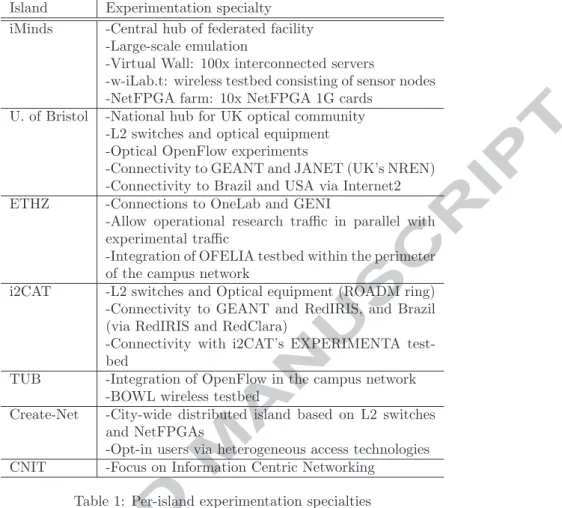
Initially, OFELIA testbed was designed with five academic partners setting up individual testbeds (called islands), within their premises. The original OFE-LIA islands include testbeds at iMinds, U. of Bristol, ETHZ, i2CAT and TUB. The design of the facility has been extended with three additional islands that have been setup by partners that were included in the project at a later stage through the so-called Open Calls process (fig:OFELIAIslands).tab:perislandspecialties shows each islands specialties and their technological capabilities.
Island Experimentation specialty iMinds -Central hub of federated facility
-Large-scale emulation
-Virtual Wall: 100x interconnected servers
-w-iLab.t: wireless testbed consisting of sensor nodes -NetFPGA farm: 10x NetFPGA 1G cards
U. of Bristol -National hub for UK optical community -L2 switches and optical equipment -Optical OpenFlow experiments
-Connectivity to GEANT and JANET (UK’s NREN) -Connectivity to Brazil and USA via Internet2 ETHZ -Connections to OneLab and GENI
-Allow operational research traffic in parallel with experimental traffic
-Integration of OFELIA testbed within the perimeter of the campus network
i2CAT -L2 switches and Optical equipment (ROADM ring) -Connectivity to GEANT and RedIRIS, and Brazil (via RedIRIS and RedClara)
-Connectivity with i2CAT’s EXPERIMENTA test-bed
TUB -Integration of OpenFlow in the campus network -BOWL wireless testbed
Create-Net -City-wide distributed island based on L2 switches and NetFPGAs
-Opt-in users via heterogeneous access technologies CNIT -Focus on Information Centric Networking
Table 1: Per-island experimentation specialties
The design of the facility was also challenging concerning the layer 2 (L2) connectivity between all islands, which has been accomplished by interconnect-ing the testbeds through the iMinds island actinterconnect-ing as the L2 hub. Islands are connected either via VPNs over the Internet or via native G´EANT [9] L2 con-nectivity.
The OFELIA experimental network design was targeted to offer a diverse and powerful OpenFlow infrastructure that allow experiments on a multi-layer and multi-technology network. The basic common infrastructure in order to conduct experimentation in OFELIA, which is offered as a service to the experimenter, is the shared L2 Ethernet OpenFlow network infrastructure along with virtualized end-hosts. With this infrastructure a complete network experiment setup can be deployed. This setup includes end-hosts to establish a communication over the OpenFlow experimental network and to deploy the experiment controller(s) to program the forwarding plane of the OpenFlow network. These application end-hosts are made available by virtualized computing resources in a Infrastructure
as a Service (IaaS) like fashion. Real, physical computing, as well as other types of resources can also be provided by each individual island in co-operation with the experimenter to fulfill the needs of the experiment.
As part of the OFELIA project, University of Bristol and ADVA Optical Networking together are working on providing OpenFlow enabled optical devices on the U. of Bristol OFELIA island. OpenFlow support is enabled on the ADVAs ROADM (Reconfigurable Optical Add Drop Multiplexers) which are available in the U. of Bristol Island.
To operate the experimental network, OFELIA has also two separate out-of-band networks: the control and the management networks.
To enable the experimenter to register to the facility, configure their exper-iments, request, setup and release resources, the OFELIA facility provides an experiment orchestration software or control framework, the OFELIA Control Framework(OCF)[10], developed within the project.
The following sections will illustrate the design of the different elements of the OFELIA testbed in greater detail.
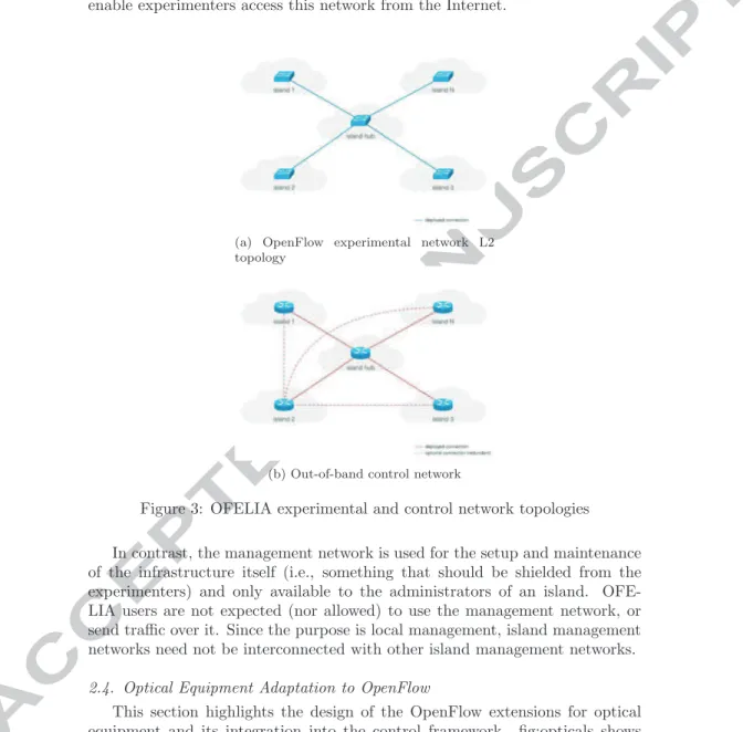
2.1. OpenFlow Experimental Networks
The OFELIA experimental network is the core component of OFELIA test-bed (fig:networksDesign(a)). The core network is designed to offer a plain L2 OpenFlow-enabled Ethernet segment, directly connected to the servers host-ing virtual machines(VMs). In addition to the basic infrastructure, the testbed was designed to allow each island to offer additional specialized resources, by di-rectly connecting them to the OpenFlow network. Example of such resources are the Virtual Wall[11] and the w-iLab.t[12] in iMinds’s island or the BOWL[13] infrastructure in TUB. tab:perislandspecialties shows each island’s specialties regarding the capabilities of the diverse experimental networks.
As a principle, the OpenFlow experimental network is designed for a flexible, configurable and clean resource separation, without limiting the experimenta-tion capabilities, specially OpenFlow features, of the OFELIA user. In this sense, to take the most out of the infrastructure, the majority of the island designs allow arbitrary virtual topologies by physically connecting OpenFlow switches in a partial or full mesh topology, and by connecting each of the vir-tual end-hosts or servers to multiple switches.
As many experimenters run different experiments over the same testbed substrate, interference between the network resources being used is potentially possible. Therefore, the resources associated with each experiment should be properly isolated. This isolation is performed through the concept of slicing of the testbed: slices consist of resources which are explicitly reserved to be used by the experimenters and the configuration associated with them. They compose the main base of runnable experiments and also encapsulate the state of the experiments (e.g., started, stopped, etc.).
By design, the objective was to give the experimenter enough flexibility to run experiments without being constrained by slicing practices, and particulary in the network slicing. In an OpenFlow network a slice can be defined by a
subset or portion of the traffic that the network carries which control, via the OpenFlow protocol, is given to a certain OpenFlow controller. This concept is generally referred to as flowspace.
Several network slicing strategies were evaluated to achieve experiment (slice) traffic isolation, such as pure MAC-based slicing, VLAN-based slicing and even on-demand arbitrary flowspace allocation. The implementation details of the slicing are exposed in section 3.1.1.
2.2. Computing Resources
One of the objectives of the project is to provide computing resources as a service (IaaS) to the experimenters, in order to deploy endpoint applications and OpenFlow controllers. The basic requirements of this service were:
• Network awareness: due to the nature of experimentation within OFE-LIA, the data-plane network configuration of the equipment is critical, spe-cially L2 (topology, STP...). In contrast to other testbeds, where comput-ing resources (usually virtualized computcomput-ing resources or virtual machines or VMs) only require L3 connectivity, OFELIA computing resources must be “L2 aware”. The configuration of the network for the computing re-sources should not interfere with the experimentation, and the equipment networking information, such as physical L2 topology, must be explicitly exposed to the OFELIA experimenter.
• Scalability: the deployment should be sufficiently scalable to support concurrent usage of the infrastructure without affecting the overall exper-imentation.
• Cost: the solution adopted should be efficient in terms of cost, both in CAPEX and OPEX. In terms of operational costs, the solution should be easily integrated with the Control Framework, for automated provisioning and monitoring of computing services.
• Performance: although not the main requirement, since the service is provided on a best-effort basis, the solution should impact as little as possible the overall performance of the computing resources, both in terms of computing power and network bandwidth.
Given the requirements and constraints exposed, design of the computing infrastructure was decided to be based on a computing virtualization technol-ogy. An initial study in 2010-2011 was made in [14] where several technologies, frameworks and tools were evaluated for such purpose. It was decided that initally XEN-based VM support would be implemented first for the server vir-tualization.
2.3. Control & Management Networks
To support the operation of the experimental OpenFlow network, two out-of-band networks have been designed; the control and the management network. The former, by design, is meant to support and make available the different OFELIA services, like the entry point for experimenters to the testbed, the
access to the testbed orchestration software or the access to the experiment resources (e.g. a virtual machine), as well as other OFELIA internal services, such as DNS. In addition, the control network may also be connected to other island-local infrastructure (e.g., non-OFELIA equipment). Moreover, the con-trol and the experimental networks are designed to be interconnected between islands, and therefore the control network is, by design, routed between islands, as shown on fig:networksDesign(b). Layer 3 VPN services were designed to enable experimenters access this network from the Internet.
(a) OpenFlow experimental network L2 topology
(b) Out-of-band control network
Figure 3: OFELIA experimental and control network topologies In contrast, the management network is used for the setup and maintenance of the infrastructure itself (i.e., something that should be shielded from the experimenters) and only available to the administrators of an island. OFE-LIA users are not expected (nor allowed) to use the management network, or send traffic over it. Since the purpose is local management, island management networks need not be interconnected with other island management networks. 2.4. Optical Equipment Adaptation to OpenFlow
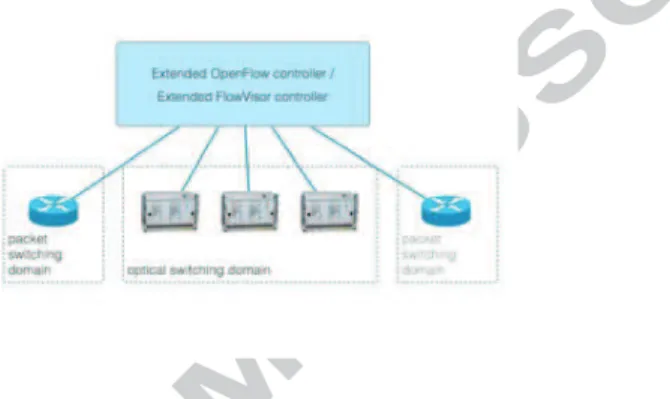
This section highlights the design of the OpenFlow extensions for optical equipment and its integration into the control framework. fig:opticals shows
the integration approach in which OpenFlow enabled circuit packet devices are controlled by circuit extended OF controller virtualized via via a new element called optical FlowVisor [15]. It assumes that each network element (NE) is represented as an individual OpenFlow enabled optical switch. The proposed approach utilizes OF Circuit Switching Extensions (v0.3) [16] in order to de-scribe circuit switching features of the optical switch. The OF controller can therefore manage packet and circuit switching domains and it is able to see the optical network topology as well as the optical layer specific information, e.g., wavelengths available on OF ports. The switch and network discovery process is thus accomplished using the extended OF protocol. On the other hand resource allocation is achieved using one of the following two methods: a) OpenFlow with integrated GMPLS control plane b) a pure OpenFlow approach.
Figure 4: Unified circuit switching(optical) and packet switching control plane The ultimate goal of the adaptation of the optical equipment is the inte-gration of the Extended Optical FlowVisor into the OFELIA Control Frame-work, where it will be aware of both the packet and circuit domains. This will require extending current FlowVisor’s API and the OpenFlow Aggregate Manager(AM), which in turn will make the optical equipment available via the Control Framework to the experimenters.
The OpenFlow enabled optical devices will be available from the Control Framework via an extended OpenFlow Aggregate Manager(AM). A hybrid packet-optical FlowVisor will slice both domains to provide a virtualized sub-strate for the user to experiment on.
2.5. Software Design: The OFELIA Control Framework
The OFELIA Control Framework (OCF) can be defined as the orchestration software for the OFELIA FP7 facility. The main purpose of the framework is to arbitrate, automate and simplify experiment life-cycle within the facility.
Original directives were taken from the study of the basic use-cases and the experience of previous OpenFlow testbeds already running, like GENI[17]
project OpenFlow testbeds. An analysis of the first collected requirements re-sulted in a set of design principles that steered the design of the OCF:
• Resource allocation and instantiation: software should support re-source allocation, instantiation and de-allocation for type of rere-source (e.g. OpenFlow slice or a virtual machine), and in a calendarized fashion. • Experiment/project based resource allocation: the resource
allo-cation/deallocation must be made per project and slice, being a slice the smallest indivisible entity composed by the resources necessary to carry out an experiment. Slices must be totally isolated from each other, even though they might share the same infrastructure substrate.
• Federation and island autonomy: the software architecture shall in-herently support internal (between OFELIA islands) and external fed-eration with other testbeds. That is, the coopfed-eration of the several local testbeds to support cross-testbed experimentation without affecting island operation autonomy.
• Authentication and Authorization (AA) and policy framework: OCF has to support the necessary mechanisms for authentication and authorization (in several scopes) along with a strong policy framework (also in several scopes or layers).
• Usability: experimenters should have access to comprehensive and easy to use user interface(s). In this sense, the main focus of the development will be towards a web-based user interface.
• Robustness, stability and scalability: Stability and robustness is a must. In addition, the control framework must be scalable, in terms of number of users, support for concurrent experiments and number of man-aged resources.
• Monitoring: the control framework should support monitoring mecha-nisms for both the own control framework components and the slice re-sources.
2.5.1. OCF software architecture for v0.X versions
The initial architecture design of the OCF software is depicted at fig:archs(a). This architecture is still very implementation-centric, hence very much influ-enced by the individual architecture of the several tools adopted during initial implementation phase. Nevertheless, as part of the project work-plan and fol-lowing an iterative approach, the architecture has and is evolving along with the implementation, as it will be shown in section 2.5.2. However most of the fundamental concepts behind the evolved architecture are already present in the design. fig:archs(a) shows the basic structure of a single testbed soft-ware stack, composed fundamentally by two types of components and formally corresponding to two separate layers. It is worth stressing that although 0.X versions architecture was originally conceived for a single testbed deployment, the correct design allowed to inter-federate different instances of OCF running in distributed testbeds.
(a) Current software architecture (v0.X) for a single testbed (island)
(b) OFELIA’s new software architecture (v1.X) for a single testbed
Figure 5: OFELIA Control Framework architecture evolution
tions: the user interface (web frontend) and the so-called Clearinghouse (GENI terminology). The Clearinghouse is in charge of the testbed projects, slices and users state management, as well as performing user authentication and autho-rization.
Lower layer components contains the components called Resource Managers (RM) and Aggregate Managers (AM). Resource Managers are components in charge of taking care of resource management solely (e.g., a virtual machine, a flowspace...), maintaining reservation state of the resource, performing resource allocation, setup, monitoring and de-allocation (in the example two RMs are shown, for virtual-machines and OpenFlow resources).
Aggregate Managers in their turn, have the same API or APIs northbound as the RM, but in contrast they do not perform resource management on their own. The mission of AM is to “stitch” or compose resources forming a more complex resource, and take care of the atomicity and proper allocation, setup, monitoring and de-allocation of the compound resource.
The federation mechanism, not shown in the figure for simplicity, is accom-plished by allowing higher layer component instances (Frontends) to connect to other testbeds RM/AMs, effectively allowing users to use resources across several testbeds.
Nevertheless, this architecture presents some limitations. First, the higher layer component (frontend) should be split into the two logically separated mod-ules, the user interface and the Clearinghouse (CH), allowing more user inter-faces to be used. Along with this split, a formal definition of the interinter-faces among these components and the interaction with the AM/RM layer is also required. In addition, due to the implementation-centric nature of the archi-tecture, it lacks a formal definition on how the combination or “stitching” of resources is handled (aggregation layer), recursion properties of the architecture or how and where policy framework should be implemented.
2.5.2. OCF software architecture for future v1.X versions
fig:archs(b) shows the evolved software architecture design, intended to be implemented starting from version 1.0 of the OCF on. The architecture
flects the conclusions obtained from the OFELIA contributions in discussions regarding Slice-based Federation Architecture (SFA) with other projects such as GENI.
There is a formal definition of three separate layers; the user interface layer, the Clearinghouse layer and the AM/RM layer. Interactions and interfaces among these layers are formally defined. Federation is still taking place allow-ing user interfaces to interact with other testbeds AM/RM layers while local Clearinghouses deal with authorization of received requests.
The new architecture defines that AMs and RMs may form a hierarchical chain, also due to the fact they all speak the same APIs and have the same authorization and authentication frameworks. This will be achieved since all the different AM/RMs will be based on the AMsoil [18]. This software package framework can be considered as the base toolset to build OFELIA AMs. It encapsulates common tasks which are performed by every AM/RM, such as Authentication & Authorization, interfaces such as the native OFELIA API, GENI API v3 [19] or SFA [20] wrapper and common AM/RM abstractions and mechanisms, like booking and monitoring logic.
The aggregation of AMs is something allowed by the architecture itself and may be implemented depending on the specific management requirements (re-source aggregation). The architecture also defines that AM/RM component may implement policies locally according to the operational needs. To accomplish this, OFELIA developed the pyPElib library [21]. pyPElib allows to add rules to evaluate any request and any element of the AM’s data model depending on local policies. Finally, these components should also be in charge of resource monitoring.
3. Implementation 3.1. Network deployment
The following sections expose some details on the technical solutions adopted during the deployment and operation of the three OFELIA networks: the OpenFlow-enabled experimental network, the control network and the manage-ment network. In addition, an overview on the implemanage-mentation of the OFELIA hub island in Belgium is given.
3.1.1. OpenFlow experimental network configuration
The experimental network spans all of the current deployed islands, including non-public islands. The network conforms a pan-European single OpenFlow-enabled (v1.0) Ethernet segment, allowing L2 experiments across different coun-tries. As with the rest of the networks, the experimental network has the central hub in iMinds. Roughly 25 OpenFlow-enabled switches from different vendors, such as NEC, HP (i.e. the case of i2CAT island in fig:OFELIAi2CATIsland) or PRONTO, have been deployed, being approximately 20 of them available on public OFELIA islands.
Figure 6: i2CAT island de-ployment(Barcelona) Most of the switches allocate a significant
number of ports to be managed by the Open-Flow protocol, and these ports are interconnected forming either a partial or a full mesh topol-ogy (fig:networksDesign(a)). At the same time, servers are in general connected to more than one switch, forming a flexible environment for experi-mentation. Experiments can use topologies form-ing loops, by choosform-ing a loop inducform-ing flowspace via the OCF. The software cautions the user that the requested flowspace contains loops, either lo-cally in the island or across multiple islands.
Each island uses a Flowvisor[22] or VeR-TIGO[? ] instance to slice the experimental
net-work. VLAN-IDs based slicing was selected after testing several slicing schemas, to offer the maximum flexibility but mostly due to scalability issues with Open-Flow v1.0 and the limited number of Ternary Content Addressable Memory (TCAM) entries on switches. Note that current OpenFlow switches often ex-tend upon legacy hardware implementations, which are designed to separate traffic using VLANs mostly. The decision was that a VLAN-ID or a group of VLAN-IDs will be assigned to each slice. This slicing mechanism guarantees a proper layer 2 isolation for each slice while keeping the number of TCAM entries in the switch used per slice to a reasonable amount, ensuring the scalability of the testbed. In the case an experiment itself needs VLANs, a range of VLAN-IDs will be assigned which provide both slice isolation and the ability to still experiment with VLAN-IDs.
However, individual islands or testbeds can freely use other slicing mecha-nisms for particular slices within the island (e.g., IPv4 flowspaces). Moreover, neither the design of the OFELIA experimental network nor the OCF preclude that the slicing mechanism used will always be VLAN slicing.
This interconnection is based on a minimum of 1Gbit/s L2 circuits via the GEANT network when possible and VPN tunnels over the public Internet. For GEANT interconnection, the circuit is partitioned to provide dedicated and guaranteed bandwidth for a control network channel. Additional VPN tunnels and circuits can be deployed in a mesh topology for redundancy in both control and experimental networks.
3.1.2. Control & management network configuration
The control network (fig:networksDesign(b)) is an IPv4 routed out-of-band network that interconnects the different OFELIA islands. The network uses a private addressing schema, with a subnet assigned to each island. Advertisement and routing between the control network subnets is performed by OSPF running on the gateway at the respective islands. Each island has at least one connection to the OFELIA hub, and additionally other redundant connections to other islands. These connections are deployed via either a dedicated GEANT(pan-european data network dedicated to the research and education community) L2
link or via a VPN over the public Internet.
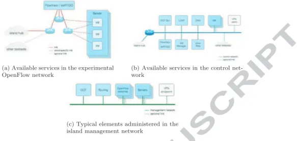
(a) Available services in the experimental OpenFlow network
(b) Available services in the control net-work
(c) Typical elements administered in the island management network
Figure 7: Available services in the different networks of the OFELIA testbed Each island provides several services, like the OCF front-end, as well as more generic services such as LDAP (deployed in the hub) and DNS through the control network. This network is also providing access to users, via the VPN endpoint (OpenVPN), to the whole facility and in particular also to the server infrastructure which in turn is connected to the experimental network. Each island also provides outbound Internet connectivity from the user’s VMs.
The management network (fig:networksDesign(c)) is used for monitoring and administrative tasks over the infrastructure. The management network is so far an optional network: in some (parts of) islands its function may be fulfilled by the control network, having the advantage of being simpler to implement, but jeopardizing the separation from user traffic. Both the control and management network may be implemented as either dedicated LANs, or a VLAN over the island’s control network segments.
3.1.3. OFELIA hub
The OFELIA islands are currently interconnected in a star topology to the OFELIA hub, located at iMinds offices (Belgium). Aside from the main links to the hub, there can be additional redundant links between other islands. The hub infrastructure includes some centralized control infrastructure such as the main LDAP server and public OFELIA registration server. An OpenVPN server is hosted to allow external access to the control network for users, and to inter-connect control network gateways from the respective islands. For the latter, a backup OpenVPN hub is available at TUB, with switch-over between both control network OpenVPN hubs using OSPF. The OpenVPN server also acts as a hub for the experimental networks. These are interconnected through L2
tunnels, and bridged using Open vSwitch (which supports OpenFlow). In addi-tion to interconnecaddi-tion over the Internet, islands may also connect to an NEC IP8800 OpenFlow-capable switch located at the hub through dedicated circuits (e.g., using the GEANT network or other NRNs). The dedicated circuit carries experimental, but also control network traffic. For islands using a dedicated cir-cuit, it replaces the OpenVPN tunnels. The Open vSwitch bridge and NEC hub switch are interconnected to complete the OFELIA L2 experimental network. 3.2. Computing equipment deployment
The study within [14] concluded that to fulfill the requirements exposed in
sec:serverdesignaservervirtualizationtechnologywiththeabilitytocustomizetheinternalnetworkingandf ree− licensesof twareshouldbeused.StrongcandidateswereXEN[?]andKV M [?], togetherwiththelibvirt[?]library.C
Roughly 20 servers have been deployed in OFELIA, both for experimenter Virtual Machine(VM) storage and for internal services. For the former, most of the severs are running Debian 6.0 (Squeeze), although some islands have special deployments.
3.2.1. Internal Virtual Machine server networking
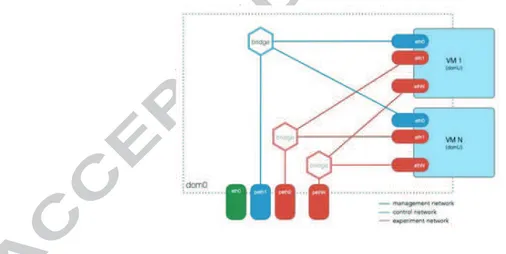
The current production VM server network configuration is based on a par-ticular setup for multi-bridge support (including VLAN support). It uses the standard Linux kernel bridging. The main objectives of this initial implementa-tion were: i) support for multiple experimental interfaces and at least a control network interface (out-of-band) per VM; ii) ensure that virtual machine exper-imental interfaces have a one-to-one mapping with server physical interfaces, clearly exposing L2 topology to the experimenter; iii) full support of 802.1q tagged frames from the virtual machines experimental interfaces; iv) configu-ration should support implementation of L2 anti-spoofing (MAC, VLAN) and rate limiting strategies.
fig:virtServerNetworking exposes graphically the current networking inter-nals of the XEN servers. Each VM is provided with an out-of-band interface, connected to the control network (bridge over peth server interface). This spe-cific bridge is usually created over a virtual tagging/untagging interface in the server or domain0, which for security and practical reasons transparently tags and untags control frames in the control and management network, usually a shared out-of-band L2 segment.
The configuration also allocates a bridge per experimental (connected to the OpenFlow network) server physical interface that needs to be shared with the VMs. The Control Framework software ensures that the naming of the interfaces within the virtual machine is consistent with this mapping, reserving the first assignment (eth0) for the out-of-band control interface, and then assigning the rest of the names to experimental interfaces accordingly. The exact connection details, such as port and datapath-id where the interface is connected to, are exposed in the OCF front-end.
3.2.2. Known limitations of the internal server networking and further develop-ment roadmap.
The current configuration, while being suitable for most of the experiments within OFELIA, presents a few limitations that have to be taken into account during the experimentation. On one side bridges are inherently MAC learning switches and not OpenFlow controllable, which may eventually impact exper-imentation if not taken into account. Also, bridges are shared between the several virtual machines within a server, which allows them to communicate through a direct path within the server network, without reaching the Open-Flow controlled domain. And last, but not least, currently there is a limited ACL and rate-limiting functionality implemented in the bridges.
There is an effort on-going to produce a new configuration which should replace Linux bridges with Open vSwitch instances. This will eventually allow OFELIA to better expose the internal networking of the server for experimental traffic. At the same time, this will potentially restrict traffic to prevent spoofing and cross-slice traffic injection, and use the advanced traffic control features of Open vSwitch such as rate limiting.
3.3. Adaptation of optical equipment to OpenFlow
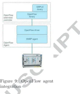
As explained in sec:opticaldesign, inordertointegrateopticaldevicesintotheOF ELIAControlF ramework, w OpenFlow based Circuit Switch Abstraction (OF Agent): an
Open-Flow enabled switch is exposed to a controller by representing the switch as one or more flow tables in an OpenFlow pipeline [? ]. Current OpenFlow speci-fications concentrate mainly on packet switching domains, although an adden-dum was added to cover the optical domain, considering SONET/SDH, Optical Cross Connects (OXCs), and Ethernet/TDM convergence as circuit switched technologies for OpenFlow 1.0[16].
Figure 9: OpenFlow agent integration
On top of these extensions supporting circuit switching, OFELIA proposed a generic and ex-tended optical flow specification [? ]. In the proposed definition, an optical flow can be iden-tified by a so-called flow identifier, composed by port, wavelength of the optical carrier, bandwidth associated with the wavelength and constraints specific to the physical layer (e.g. sensitivity to impairments and power range). The OpenFlow switch abstraction for Network Elements is done by the OpenFlow agent software which consists of a Simple Network Management Protocol (SNMP) interface which is glued together with the Open-Flow channel via an abstracted resource model. Each Network Element with an agent becomes an OpenFlow enabled switch. This approach can be seen in fig:opticalAgent. The SNMP management interface offers rich functionality that enables the data-plane configuration and retrieval of the ac-tual configuration of the NE.
Controller to manage OF enabled circuit switches: the extended OpenFlow controller, at the same time, can perform discovery of the underlying topology either directly from the OpenFlow switch or using the Generalized Multi-Protocol Label Switching (GMPLS) control plane, or with a combination of both. From this point on, the controller can build a topology map of the optical network and, based on the user’s requirements, can push flow entries (through GMPLS or Pure OpenFlow approach) to switches to establish cross connections in the optical domain.
The current prototype is based on ADVA’s FSP 3000 ROADM equipment[? ], using ADVA’s implementation of the GMPLS control plane. It can provision optical paths in two modes i.e., loose and explicit paths. In the OpenFlow-GMPLS integrated approach, resource allocation is performed by the OpenFlow-GMPLS control plane, but the OpenFlow controller can build the topology from the OpenFlow messages. Depending on the request the controller can issue loose or explicit path requests to the GMPLS control plane which acts as an application on top of the controller. The GMPLS control plane takes care of resource allo-cation and power levelling and sets up the corresponding request path. This ap-proach allows utilising GMPLS Path Computation Element(PCE) features, like path computation with optical impairments which were not available in current OpenFlow controllers. In the duration of the project a stand-alone pure Open-Flow solution was also developed. Here OpenOpen-Flow CFLOW MOD messages are used to update flow tables instead of the GMPLS [? ]. The Flow setup using pure OpenFlow approach assumes an OF agent on each Network Element in the network.The OF agent instantiates or deletes appropriate cross-connections via SNMP upon receiving CFLOW MOD messages. Extended OpenFlow messages were also introduced to accommodate power, constraints and impairments
tures of the NE. This development provided an opportunity to also compare the integrated GMPLS-OpenFlow approach with pure OpenFlow approach over the OFELIA facility [? ].
Optical infrastructure slicing using FlowVisor: with the OpenFlow extensions in place the next goal was the integration of the mentioned solutions to the facility. As detailed in other sections OFELIA supports infrastructure slicing using the OpenFlow based virtualization tool called Optical FlowVisor. The Optical FlowVisor (OFV) [15] provides the ability to the experimenter to add also optical nodes to his experiment. The Optical FlowVisor has been extended accordingly so that it has visibility on both packet and optical domains and it can slice in the circuit domain based on ports and wavelengths as detailed in circuit flows.
3.4. The OFELIA Control Framework
The implementation of the OFELIA Control Framework [10] was split logi-cally into three distinct phases, according to the different milestones: i) imple-mentation of the first early version of the control framework, focusing on the management of the island’s local resources, but keeping in consideration the inter-island resource control; ii) the second phase devoted to empower the con-trol framework with mechanisms to allocate resources across multiple islands within the same slice (intra-federation), as well as including software improve-ments of some of the basic features implemented in Phase I, taking into account experiences acquired from the different internal and external facility users; iii) third phase continues the overall improvement of the control framework, espe-cially taking into account the requirements, suggestions and comments inferred from the regular users and the two open calls partners.
The development follows a dynamic and Agile software development, con-tinuously collecting new requirements, evolving and improving the software. All this resulted in a long list of releases of the v0.X series, from the v0.1 up to the current v0.5, and it is now gradually moving forward to the new architecture of the v1.X series.
3.4.1. Current software stack (v0.5)
Following the architecture of the v0.X series depicted in fig:archs(a) of sec:designfutarch, theimplementation Frontend/Clearinghouse This component plays two main roles. On one side,
it deals with the management of users, projects and slices within each is-land. The Clearinghouse accesses the OFELIA LDAP for synchronizing user accounts and privileges among islands and providing a unified au-thentication framework (Single Sign On or SSO). On the other side, it also acts as the AJAX-enabled web-based user interface. The communi-cation with the AMs is performed by means of specific plugins developed in Python. Each plugin provides the means to communicate and translate the resource specific description provided by an AM. The Clearinghouse is based on Expedient[? ], a module originally developed by Stanford
University, but highly adapted and extended in areas like the experiment work-flow and the Web UI.
Virtual Machine Aggregate Manager The VM Aggregate Manager (AM) deals with the management of the virtualized servers provided by the OFELIA facility to host OFELIA user’s virtual machines. The current implementation supports XEN, although AM design and implementation is inherently hypervisor-agnostic. It also comes with a Web UI for man-agement purposes. The VM AM handles the requests and takes care of the provisioning, instantiation and uninstantiation of VMs in the physical servers. The OFELIA XEN Agent is a daemon running in the physical servers, which is in charge of dealing with VM provisioning and all the hypervisor related functions including monitoring, via the libvirt library. OpenFlow Aggregate Manager is currently based on the Stanford’s tool
Opt-in Manager[? ]. The main objective of this package is to control and administer the Flowvisor configuration, the tool in charge of slicing the OpenFlow network and multiplexing concurrent usage. It comes with a Web UI which is only available to the Island Manager. It also provides an embedded email notification system for request notication to the testbed administrator(s).
3.4.2. Deployment within the OFELIA FP7 facility
The OCF software stack has been deployed in the all of the OFELIA islands and is being used to orchestrate experimentation. Each individual island consti-tutes a completely functional environment in which local (island) experiments can be carried on. For each deployment, the local administrator has control over the local resources orchestrated through the Control Framework. Moreover, is-land administrators are able to define their own policies concerning resource in-stantiation/allocation, within the general policy framework of OFELIA. These capabilities will be further extended when Aggregate Managers adopt pyPElib-based policy engines [21] (still in beta for the VM AM at the moment of writing this document).
Experimenters have the option to log in to any of the public OFELIA fron-tends and create projects and slices. By design, as exposed in the architecture, project and slice state resides only in the frontend used, regardless of which resources, and from which AMs they are allocated.
At the time of writing this article, federation of the different OFELIA is-lands managed by OCF has been deployed in production. After the federation, each island frontend is able to communicate with all the Aggregate Managers within the OFELIA facility. This enables experiments from any of the OFELIA frontends to create projects with resources across the whole federated testbed. 4. Experimentation in the OFELIA Testbed
As a testbed, OFELIA aims to provide a realistic wide area platform to the research community in order to experiment and test new ideas. Since OFELIA
has been open to the public it has hosted already some interesting experiments. In the following subsections some of the most relevant experiments will be de-scribed, showing the capacity of OFELIA facility to help the testing of new concepts.
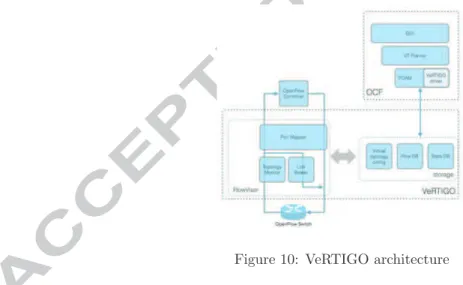
4.1. VeRTIGO (ViRtual TopologIes Generalization in OpenFlow networks) FlowVisor is the most popular tool used to slice an OpenFlow network into several sub-instances, each one assigned to a different controller. It is considered the de-facto standard to perform network virtualization, even though it does not allow to instantiate arbitrary virtual network topologies, i.e., topologies that de-part from the physical one at substrate level. Due to its tight integration within the OFELIA Control Framework, this is a major limitation since researchers willing to run their own experiment on top of OFELIA testbed will be forced to test it on a very limited set of network topologies. Furthermore in its current implementation within the OCF, experimenters are forced to manually select the (physical) links and nodes belonging to their virtual network instance. The objective of VeRTIGO is to overcome these limitations by allowing the instanti-ation of generalized virtual network topologies on top of the OFELIA testbed; in particular, VeRTIGO enables experimenters to run their experiment on a completely arbitrary topology that may span several OFELIA islands. These topologies are based on the concept of “virtual links” realized as aggregation of multiple physical nodes and links. Moreover, a tight integration of VeRTIGO within the OCF enables the automatic setup of whatever topology decided by an experimenter (e.g. on a dashboard) on top of OFELIA thanks to a mechanism that will both optimally embed the requested virtual topology into the physical one and then automatically instantiate it on the testbed to let the experiment be properly executed (i.e., without the need for any “manual” provisioning).
fig:vertigo shows the software architecture of VeRTIGO and its interrelation with the OCF. The main components are: i) the topology monitor which an-alyzes the OpenFlow messages and the virtual topology configuration, ii) the port mapper that edits the switch-to-controller messages by replacing the port number values with ones consistent with the virtual links configuration, iii) the link broker, which creates OpenFlow protocol messages directed to switches and iv) the VT Planner, a Virtual Network Embedding tool implementing a path selection algorithm to efficiently aggregate physical nodes and links into virtual links. The VeRTIGO framework is currently being integrated into the OCF, however the underlying mechanism replacing FlowVisor has been heavily tested as discussed in [? ], where Key Performance Indicators(KPIs) like latency over-head against FlowVisor and responsiveness against physical link failures have been studied. These results show the effectiveness of the proposed Network Virtualization layer that can unleash researchers capability to test their own experimental applications within a controlled testing environment provided by the OFELIA testbed facility.
4.2. Information-Centric Networking (ICN)
Information-Centric Networking (ICN) is receiving the attention of a large research community. The basic idea behind ICN is to re-design the networking layer in order to support two main primitives, namely to put content element in the network and to fetch content elements from the network, identifying the content with proper name.
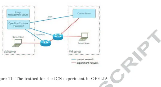
Two possible approaches have been identified to support ICN using the SDN paradigm: a “long term” [? ] and a “short term” [? ] one. We focus here on the latter one, i.e., supporting ICN over OpenFlow 1.0, so that we could use the equipment deployed in the OFELIA testbed for our experiments. We started from an ICN solution called CONET, defined in [? ], which in turn is derived from CCN/CCNx [2]. In these solutions, ICN requests are forwarded toward the nodes hosting the content, which reply with data packets. Intermediate nodes can process data packets and cache the requested content (“in-network” caching) so that they can serve further requests for the same content. The idea is to use SDN/OpenFlow to control the routing of ICN packets (Interests and Data) in the network, providing the means to efficiently realize the in-network caching.
In CONET, the content names are called (ICN-ID) and are carried within a newly defined IP option [? ] in IPv4 or IPv6 header. Current OpenFlow 1.0 equipment does not support operation based on the information carried in the IP options, therefore we decided to map the content name into a fixed length tag (4 bytes) to be transported in the UDP source and destination ports fields. This mapping is performed by a border node at the edge of an SDN based domain.
Figure 11: The testbed for the ICN experiment in OFELIA
The configuration of our experiment, deployed and run in the Barcelona
is-land of the OFELIA testbed, is shown in fig:icntestbed.W ecanonlydescribetheexperimentathighlevelhereandwe
4.3. OpenFlow Carrier grade experimentation within OFELIA from the SPARC FP7 project
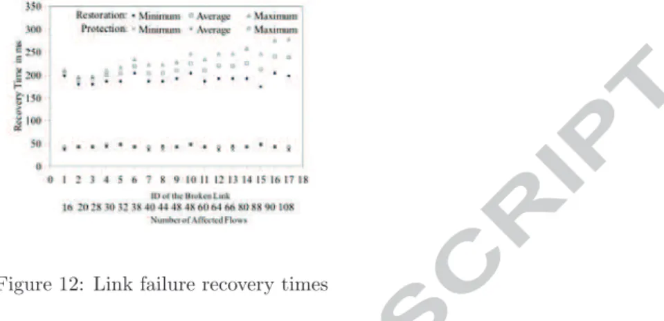
The FP7 SPARC (SPlit ARchitecture Carrier-Grade Networks) [? ] project studied OpenFlow extensions in carrier-grade networks, which offer high capac-ity to support hundreds of thousands of customers and assume extremely high availability. These have a requirement for traffic to be recovered within 50 ms [? ] after a failure. In the project, controller-based restoration and switch-based protection schemes were implemented. For controller-switch-based restoration, an alternative path is established after a failure is detected. For switch-based protection, a disjoint end-to-end alternative path is established before a working path failure occurs. When a failure is detected in the working path, the ingress switch redirects traffic to the alternative path using the group table concept introduced in OpenFlow v1.1 [? ]. Extensive emulation experiments [? ] on large-scale pan-European topologies looking at restoration and protection were run on the OFELIA facility. In these experiments, link and node failures were considered. In link failure experiments, one of the links between switches was failed by disabling Ethernet interfaces of the link; and in node failure experi-ments one of the switches was failed by powering off the switch. The link failure experiments were carried out to test scalability with respect to a number of flows. In these experiments, the number of flows was increased from 160 to 16000. For restoration, the recovery time scaled linearly with the number of affected flows in the network and for protection, the recovery time was about same regardless of the affected flows. The maximum value of the recovery time in the link failure experiments was 2.6 seconds for restoration and 48 ms for protection. For node failure experiments, 3200 different flows were considered in the network. The results were similar to the link failure experiments in which
the recovery time increased linearly in restoration and was about constant for protection.
Figure 12: Link failure recovery times
fig:sparc shows that OpenFlow can restore traffic, but its dependency on the controller means that it will be hard to achieve 50 ms restoration in a large-scale carrier grade network. It also shows that OpenFlow can achieve the carrier-grade requirement of a 50 ms interval if protection is implemented in these networks to recover from the failure. Other experiments, which were performed in the OFELIA testbed, were in-band control experiments [? ]. In these experiments, user and control traffic (traffic to or from the controller) shared the channel, and OpenFlow switches establish OpenFlow sessions with the controller via paths through the other switches in the network. The experiments were carried on different types of topologies: linear, ring, star and mesh topologies and the time to establish a session between a switch and the controller was calculated. The considered mesh topologies were large-scale pan-European topologies that were used in the failure recovery experiments. The results with all topologies showed a linear relationship between the switch connection time and the shortest distance between the switch and the controller. For large-scale pan-European topologies, it took about 6 seconds to connect all switches (37 nodes) with the controller.
4.4. Power-aware routing in Software-Defined Networks
Previous work resulting in a degree thesis studied power-aware routing in SDN testing their new algorithms in the OFELIA island located at i2CAT’s venue. This work considered the growing interest around optimization of com-puter networks with techniques such as load balancing and power saving. Ap-plying linear programming in an SDN context, a new algorithm to calculate the energy cost of a certain route was elaborated and implemented in C/C++ as a network controller over NOX. The energy cost model was deduced by taking real measurements of the equipment used in different load conditions from innactive to full load. The controller then was able to query the OpenFlow switches about their traffic statistics and map them with a specific energy consumption.
OFELIA came into play in order to test the effectiveness of the produced routing model in an almost real-world scenario. Using OFELIA CF the val-idation of the model was carried out by provisioning a slice of the resources available in the i2CAT’s OFELIA infrastructure composed at that moment of 5 NEC OpenFlow-enabled switches in a meshed topology and virtualizing servers where endpoints and the controller’s VMs were hosted. Modifications in the network conditions were simulated by changing the requested FlowSpace ac-cordingly.
4.5. Multiple Service Load Balancing with OpenFlow
Load balancers have a decisive role in enterprise networks as they serve often as an entry point and have a major impact on the performance and the avail-ability of the network. While current load balancers are mostly implemented as specific and expensive hardware components, the implementation used in the experiment is based on the OpenFlow controllers to handle the load of multiple services without the necessity for a specific piece of hardware.
Multiple service Load Balancing (LB) with OpenFlow brings a known and proved concept to a new technology. It is an approach to deploy a flexible and dynamically extendable LB for multiple services, as it is used in today’s data centers, on OpenFlow capable Hardware. Some benefits of the new technology are used to cover special demands of a service and are designed to keep the LB as effective as possible. On the other hand it use the known NAT-based LB concept which makes it easy for any network operator to deal with.
The OFELIA facility was used to evaluate the concept and test which perfor-mance is currently delivered by OpenFlow capable hardware switches. Therefore a resource slice at TUB-island was allocated and connected to the special per-formance testing equipment from Ixia. Ixia equipment was used to simulate real HTTP traffic, clients to servers, as well as to evaluate the C++ LB NOX plug-in developed at TUB. The outcome showed some interesting measurement results regarding the current hardware restrictions, related to the processed OpenFlow action. The concept and results were presented and published [? ] to the networking research community.
5. Federation with external testbeds
The interest for OpenFlow related research is driven by new ideas that evolve over time. OFELIA’s architecture was designed to provide a set of core services and common practices for interconnecting OpenFlow testing sites. This allows federation of heterogeneous testing sites each focusing on specific research areas in the context of OpenFlow. Currently, OFELIA contains a wide range of islands and research topics, such as: optical and wireless research equipment and media delivery equipment, allowing to experiment in a variety of research fields, like content centric networking, virtual topology management or routing (e.g. energy efficient routing schemes) among others.
Our final goal is a fully distributed architecture that allows independent creation, autonomous operation, and dynamic interconnection of islands without
the need for a (or at least just a minimal) central hub. A distributed architecture also mitigates the project administrative constraints that inevitably exist within all experimentation based activities. OFELIA’s architecture is designed so that the facility will also exist beyond the administrative end of project OFELIA. When none of the existing islands meet requirements of the research community, we encourage other researchers to build their own OpenFlow islands and connect with the swarm of already existing OpenFlow islands.
In the last couple of years we have seen deployment of various testbeds and testing infrastructures in the context of Future Internet research funded by var-ious national or European bodies. Federating these research infrastructures is one of the more nebulous goals of the testbed community, especially as the use cases remain blurry. A federation of testing infrastructures may be used to study details of a specific research topic in more detail within an isolated environment. For OFELIA, this area of interest has been limited to development of control architectures and applications for Software Defined Networking. Research on the basic OpenFlow protocol is out of scope for OFELIA (except for the opti-cal extensions). However, a new European project named ALIEN FP7 [? ] is focusing on research on the OpenFlow protocol itself. Alternatively, federating research infrastructures may serve as a nucleus for building a new Future Inter-net that incorporates new technologies and architectural principles. Academic as well as commercial network operators may join such a nucleus, thus trans-forming the existing Internet into the Future Internet, whatever it might look like in the end. Despite this uncertainty of the final goal of a federation, many partners and users of OFELIA have expressed interest in connecting OFELIA and its islands to other OpenFlow related testbeds. One can think of various stages of integrating heterogeneous (OpenFlow based) testbeds:
1. Probably the simplest of the federations is the provisioning of plain layer-2 connectivity for exchanging experimental traffic without any further coor-dination of resources. This includes the need for manual (non-integrated) configuration of resources in both testbed environments. This stage is al-ready accomplished between the different OFELIA islands, by implement-ing L2 dedicated tunnels over experimental backbones such as GEANT, or plain tunnels over the public Internet. Any other facility can connect its network resources, being OpenFlow or not, extending the experimentation network.
2. A shared Clearinghouse functionality that enables at least common user credentials for authentication and authorization for accessing resources. The different frontends residing at each island act as an authorized entity against the AMs of the other islands allowing the experimenter to be able to allocate federated resources.
3. A common control framework for deployment and configuration that gives users a simple way of creating a new experiment. The OFELIA Control Framework is the realisation of such a control framework, and it is de-signed to be easily extended to other testbeds, by means of a modular and reusable software architecture. The OFELIA Control Framework in
tion provides a common implementation base, called AMsoil, to facilitate the creation of AMs for new types of resources.
4. A common data management framework for describing experiments, col-lecting data, and analysing results.
The first experimental testbeds were deployed as isolated islands each follow-ing their own process flows for deployfollow-ing and controllfollow-ing experiments, finally yielding a zoo of control frameworks. A number of projects for harmonizing these control frameworks have been conducted in recent years, but a single uni-fied control framework is still not in sight. Although, a set of common design principles has emerged from these discussions based on the SFA inspired GENI architecture. Within the OFELIA project, we have started to migrate the “Ex-pedient” based control framework towards these emerging de-facto standards, thus making OFELIA clients capable of establishing communication with other testbeds, like GENI and SFA-based testbeds.
5.1. FIBRE collaboration within FIRE
FIBRE is an FP7 project [? ] within the Future Internet Research and Experimentation unit (FIRE), which aims to create a Future Internet Research facility between Brazil and Europe. All the phases to achieve this goal are con-sidered within the project: design, implementation and validation. Federation becomes a key objective in FIBRE due to two reasons. On one hand, the inter-connection of the European and the Brazilian facilities is a must to provide an intercontinental testbed.
On the other hand, the European facility is being built by enhancing two existing Future Internet Research and Experimentation Initative (FIRE)’s fa-cilities: OFELIA and OneLab. In order to shape FIBRE’s facility, the inter-federation and physical connection of both existing European facilities is also an important objective. In this direction FIBRE is creating two more islands located at University of Bristol and i2CAT adding more dedicated equipment and interconnecting them to the existing infrastructures. The objective of these extensions is to deal with the increasing number of users coming from the fed-eration of facilities, and moreover, fulfilling the requirements to carry out the showcases proposed by FIBRE.
Secondly, as part of the FIBRE enhancements over the OFELIA Control Framework developed in the OFELIA project, the OCF is being used as the tool to manage the new islands. This fact will put the software against new use cases and a more extensive use, providing more feedback regarding bugs detection or requirements identification. The FIBRE project is actively contributing to the development and the extension of the OFELIA OCF, enriching the community of OCF users and developers.
5.2. GENI collaboration
The first academic OpenFlow testbed deployments were controlled by a tool named “Expedient” developed at Stanford University that followed some archi-tectural principles of SFA in terms of resource management and experimental
control. A number of projects have worked on control framework architectures for controlling testbeds in the last years. Although following very similar ba-sic architectural principles, this has led to a wide range of incompatible APIs, mostly differing in very specific details, making their use for researchers a te-dious task. In this situation, we decided to move “Expedient”’s architecture closer to SFA compliance. A joint activity of several project partners and led by Stanford University has been started to move expedient towards an SFA compliant implementation including support for the GENI API v2 and work on a new Aggregate Manager base class [18] implementation is currently ongo-ing, which will be available to other projects in the context of FIRE, GENI, and beyond as well. In addition Expedient’s clearinghouse functionality will face a significant rewrite and serve as identity, authentication, and authoriza-tion provider. Beyond the basic GENI APIv2 the AMsoil base class will also support an extended version for OFELIA specific needs.
Each Aggregate Manager will be based on a common code base. The AM base class (called AMsoil) shall consist of two parts: the resource-specific part and a common part. The resource-specific part implements the actual handling of resources, e.g. talking to an agent and allocating resources. The common part manages tasks which are needed by each AM, such as Identification, Au-thentication & Authorization, interface compliance (e.g. GENI AM API v2) and also manage reservations of resources.
5.3. International connections
For exchange of experimental traffic, plain layer-2 connectivity must be avail-able. A connection has been established via GEANT to the MANLAN open exchange point from Internet2. This provides in fact connectivity to the Open-Flow related testbeds in the US, Korea, Japan, and Brazil. Moreover, due to the requirements of the FIBRE project, OFELIA is acquiring an alternative link to Brazil via RedIRIS and RedClara. However, in order to balance experimental traffic load, we are also aiming towards establishing a direct link via TEIN-3 to the Asian OpenFlow communities in Korea and Japan. fig:connectivitymap depicts the connectivity map in OFELIA.
OFELIA is keen to collaborate and encourages members to be part of the community either by hosting an OFELIA island, creating a project as a user or federating with existing testbeds.
6. Conclusions
The OFELIA testbed facility has been built in order to host multi-layer and multi-technology experiments across a pan-European network fabric, the SDN paradigm being the main philosophy followed and the OpenFlow protocol used as its key enabler.
The design and implementation of OFELIA is based on three fundamental pillars: flexibility and resource diversity for the experimenter, ease of exper-iment orchestration on one side and ease of control and management for the
Figure 13: OFELIA connectivity map
administrators on the other, both achieved by the use of the OFELIA Control Framework, and finally, extensibility in the context of intra and inter-federation. To deploy OFELIA many challenges concerning different kinds of technologies and fields had to be studied and applied, i.e., server virtualization, SDN and OpenFlow, software development, networking engineering, etc. Some of these challenges are still work in progress and new ones are expected to appear until the end of the project.
The OFELIA testbed has already successfully hosted multiple interesting OpenFlow-based experiments in the fields of network virtualization, information-centric networking, carrier grade networks, power-aware routing and load bal-ancing. OFELIA is meant to take experimentation one step further through federation with other testbeds. The purpose of federation is not only to go be-yond European boundaries and expand the impact of OFELIA worldwide, but at the same time to be able to provide the research community with an extended set of resources provided by the different platforms present in the federation. This will be performed with multiple international connections with testbeds such as FIBRE and GENI.
Our experience with the testbed as users, island administrators and software developers has shown that OFELIA is a very promising platform for network experimentation. We hope that, together with the further development of the facility itself, OFELIA will be the testing ground for numerous research topics oriented towards the evolution of the Internet: a true beacon of experimentation for tomorrow’s networks.
References
[1] John Day. Patterns in Network Architecture: A Return to Fundamentals. Published by Prentice Hall, 2008.
[2] V. Jacobson, D. K. Smetters, J. D. Thornton, M. F. Plass, N. H. Briggs, and R. L. Braynard. Networking named content. CoNEXT 2009, Rome, December 2009.
[3] Henrik Lundgren, Erik Nordstr¨om, and Christian Tschudin. Coping with communication gray zones in ieee 802.11b based ad hoc networks. 5th ACM international Workshop on Wireless Mobile Multimedia (WoWMoM 2002), September 2002.
[4] Open Network Foundation (ONF). Software
De-fined Networking white paper, 2012. URL
http://www.opennetworking.org/images/stories/downloads/white-papers/wp-sdn-newnorm.pdf. [5] N. McKeown, T. Anderson, H. Balakrishnan, G. Parulkar, L. Peterson,
J. Rexford, S., and J. Turner. OpenFlow: enabling innovation in campus networks. ACM SIGCOMM Computer Communication Review, April 2008.
[6] Open Network Foundation (ONF). OpenFlow. 2012. URL
http://www.openflow.org/.
[7] Open Network Foundation (ONF). Website. 2012. URL
https://www.opennetworking.org/.
[8] OFELIA FP7 consortium. OFELIA FP7 project, 2010. URL http://www.fp7-ofelia.eu/.
[9] G´EANT consortium. G´EANT FP7 Project, 2012. URL
http://www.geant.net/.
[10] OFELIA FP7 consortium. OFELIA Control Framework (OCF). 2012. URL http://fp7-ofelia.github.com/ocf/.
[11] iMinds. iMinds’s Virtual Wall facility. 2012. URL
http://www.iminds.be/en/develop-test/ilab-t/virtual-wall.
[12] iMinds. iMinds’s w-iLab facility. 2012. URL
http://www.iminds.be/en/develop-test/ilab-t/wireless-lab.
[13] TUB. Berlin Open Wireless Lab (BOWL). 2012. URL
http://www.bowl.tu-berlin.de/.
[14] Marc Su˜n´e and L. Bergesio et al. Ofelia deliverable 5.1 -1st version of the ofelia management software. 2011. URL
1 2 3 4 5 6 7 8 9 10 11 12 13 14 15 16 17 18 19 20 21 22 23 24 25 26 27 28 29 30 31 32 33 34 35 36 37 38 39 40 41 42 43 44 45 46 47 48 49 50 51 52 53 54 55 56 57 58 59 60 61 62
Keywords: Ofelia, FP7, Testbed, OpenFlow, programmable networks, Research, Networking, Virtu-alization, Software Defined Networks, Testbed, Control Framework, Slice-based Federated Architecture
![Figure 2: OFELIA FP7 Eu- Eu-ropean facility deploymentSoftware Defined Networking (SDN) [4] is a](https://thumb-eu.123doks.com/thumbv2/123dokorg/7599244.114173/4.892.168.777.167.974/figure-ofelia-ropean-facility-deploymentsoftware-defined-networking-sdn.webp)