RESEARCH ARTICLE
An integrated method for understanding the
function of macro-lithic tools. Use wear, 3D
and spatial analyses of an Early Upper
Palaeolithic assemblage from North Eastern
Italy
Isabella Caricola1, Andrea Zupancich1, Daniele Moscone2, Giuseppina Mutri1, Armando FalcucciID3, Rossella Duches4, Marco Peresani5*, Emanuela CristianiID1*
1 Department of Oral and Maxillofacial Sciences, Diet and Ancient Technology Laboratory (DANTE), Sapienza University, Rome, Lazio, Italy, 2 Department of Classics, Sapienza University, Rome, Lazio, Italy, 3 Department of Early Prehistory and Quaternary Ecology, Tu¨bingen University, Tu¨bingen, Baden-Wu¨rttemberg, Germany, 4 MUSE, Science Museum, Trento, Trentino-Alto Adige, Italy, 5 Department of Humanities, Ferrara University, Ferrara, Emilia-Romagna, Italy
*[email protected](EC);[email protected](MP)
Abstract
The article presents an original analysis which combines use-wear, 3D modelling and spatial analyses to experimental archaeology in order to investigate Early Upper Palaeolithic flint-knapping gestures and techniques involving the use of macro-lithic tools. In particular, the methodological framework proposed in this paper was applied to the study of Protoaurigna-cian and AurignaProtoaurigna-cian macro-tools from Fumane Cave (Verona, Italy). Combining spatial analysis and use wear investigation, both at low and high magnifications, permitted the iden-tification and detailed description of the use-related traces affecting both the hammerstones and retouchers which, at Fumane Cave, were used at different stages during flint tool pro-duction. Several experimental activities were performed including core reduction, mainte-nance, and blank production together with different types of edge retouching. From a methodological perspective, the protocol of analysis permitted to codify specific traces and to produce quantitative data related to their geometry and distribution over the tool’s surface, according to the activities and gestures performed. The results obtained allowed a careful investigation of the function and the gestures associated to the use of the macro-lithic tools coming from the Protoaurignacian and Aurignacian levels of Fumane Cave while providing a methodological tool for interpreting different archaeological samples.
Introduction
Interest in the study of macro-lithic tools has increased in recent years, in relation to their potential for reconstructing the variability of adaptive human choices. First coined by Adams and colleagues [1], the term “macro-lithic tools” refers to a rather varied category of stone
a1111111111 a1111111111 a1111111111 a1111111111 a1111111111 OPEN ACCESS
Citation: Caricola I, Zupancich A, Moscone D, Mutri G, Falcucci A, Duches R, et al. (2018) An integrated method for understanding the function of macro-lithic tools. Use wear, 3D and spatial analyses of an Early Upper Palaeolithic assemblage from North Eastern Italy. PLoS ONE 13(12): e0207773.https://doi.org/10.1371/journal. pone.0207773
Editor: Michael D. Petraglia, Max Planck Institute for the Science of Human History, GERMANY Received: July 29, 2018
Accepted: November 6, 2018 Published: December 12, 2018
Copyright:© 2018 Caricola et al. This is an open access article distributed under the terms of the Creative Commons Attribution License, which permits unrestricted use, distribution, and reproduction in any medium, provided the original author and source are credited.
Data Availability Statement: All relevant data are within the manuscript.
Funding: The authors would like to acknowledge funding received for this project through the European Research Council (ERC Starting Grant Project HIDDEN FOODS, G.A. no. 639286 to E.C.). Competing interests: The authors have declared that no competing interests exist.
artefacts used for percussion, abrasion, polishing, cutting and grinding activities. The variabil-ity in the use of macro-tools in the past led to in-depth study of this category of artefacts, which has been analyzed from both a technological [2–6] and functional point of view, through the observation of macro and micro-traces [7–23]. There have also been important studies of the mechanical [24–26] and physical properties of the rocks [27], applying UBM laser profilometry methods [28], and of the residues [29–38]. Furthermore, the principles of tribology have made a great contribution to the study of macro-lithic tools for understanding the various processes that lead to use wear development [39–48].
So far, most of the functional data regarding macro-lithics comes from later prehistoric contexts–e.g. the Neolithic and Chalcolithic–while little information is available on the early use of such tools during the Palaeolithic and Mesolithic. Recent studies carried out on the tools found in the Bilancino site [49–52] and Grotta Paglicci [53], both in Italy, have emphasized the relationship between these tools and technological aspects such as plant food processing dur-ing the Upper Palaeolithic. Skills involved in the processdur-ing of different raw materials, such as plants [54–59] and minerals [60–64] have little visibility in the archaeological record. It is clear that it is necessary to intensify the functional studies on this category of artefacts, especially with regards to hunter-gatherer societies. The techno-cultural choices of these groups, for example in relation to a general evolution of human cognition and social interaction, could have been much more complex [65]. These choices encouraged the creation or the adoption of innovative technologies combined with a series of collateral activities, such as the ability to col-lect raw materials, transport strategies, the complementary use of tools to produce other tools, or to process organic and inorganic raw materials [66].
Tools used in percussion activities, such as spheroids and anvils, are evident since the earlier phases of the Palaeolithic [67–70], being made out of different raw materials and used to pro-cess different substances.
Macro-lithic tools are also related to the production of knapped stone tools. Indeed, ham-merstones and retouchers made of stone [4,21,71–73] and bone [74,75], are found in numer-ous contexts, especially related to the later phases of the Palaeolithic [4]. As an example, bone retouchers have been found in different Middle and Late Pleistocene sites [76,77,78–85,86]. Rarer are the antler billets [87–89] or wood retouchers [90].
To date, functional studies on this tool category are still lacking. Indeed, the use and the type of hammerstone or retoucher (e.g. hard or soft) is determined, or hypothesized, indirectly through the scrutiny of some morpho-metric features observed on the produced blanks (e.g. features of the impact point and the bulb, the internal and external platform angle, the dimen-sions of the striking platform and the morphology of the detachment scars or ridges of the dor-sal face) or the retouched edge (e.g. features of scars and the bulb, the inclination of the retouch scars with respect to the opposed face, and the morphology of the scars). The identifi-cation of knapping techniques has usually been carried out in combination with experimental activities and numerous contributions have been published over the years [91–98], while more generic information is available for the use of hammers on bones [99].
Even though this type of analysis provides interesting information, some limitations do exist. Firstly, the analysis of these features focuses mainly on the knapping techniques. Sec-ondly, it is an indirect analysis, which is exclusively based on diagnostic features on the “prod-uct”, even in those cases where the presence of hammerstones and retouchers or of ones potentially in the archaeological record would allow a detailed study of the percussion and retouching techniques. In this respect we often read about the presence of “fluvial pebbles”, which were probably used at the site as hammers, but have not been analysed by means of use wear analysis [100].
In this paper we present a multidisciplinary analysis of the repertoire of pebbles associated with the Protoaurignacian and Aurignacian levels of Fumane Cave. Such tools represent a valuable opportunity to detail the gestures of Early Upper Palaeolithic percussion activities, and the criteria involved in raw material selection and macro-lithic tool exploitation at the site. The combination of experimental archaeology, use wear analysis and GIS analysis allows fur-ther enhancement of the results provided by functional analysis, through the addition of quan-titative data, and its potential has been already proved by the pioneering studies performed by De la Torre and colleagues [101], Caruana and colleagues [102] and more recently by Benito-Calvo and colleagues [103–105].
Our results further confirm the reliability of this combined methodology and provide new and relevant insights regarding the variety of percussion activities performed during the early Upper Palaeolithic occupation of Fumane Cave.
The archaeological context: The Protoaurignacian and Aurignacian at
Fumane Cave
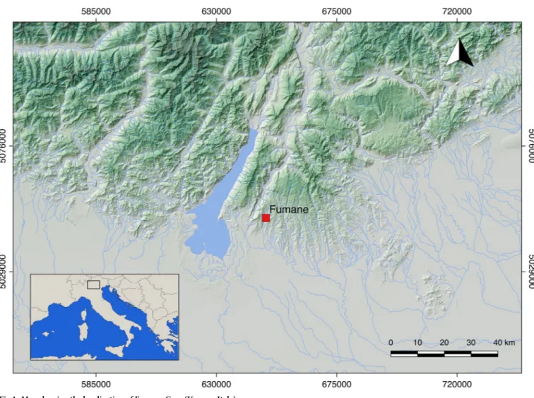
Fumane Cave is located in the Venetian Prealps (north-eastern Italy) (Fig 1). The cave has been under excavation since 1988 and is characterized by a high-resolution stratigraphic
Fig 1. Map showing the localization of Fumane Cave (Verona, Italy).
https://doi.org/10.1371/journal.pone.0207773.g001
sequence [106,107] spanning the Mousterian [108], Uluzzian [109], Protoaurignacian [110,111], and Aurignacian [112]. Today, it represents a key site for understanding the com-plex processes that led to the demise of Neanderthal populations and the spread of modern humans across Europe [113]. Layers A2 and A1 date the appearance of the Protoaurignacian to 41.2–40.4 ky cal BP, while a combustion feature embedded in the stratigraphic complex D3 Fig 2. The Protoaurignacian and Aurignacian pebbles discovered in Fumane Cave (Verona, Italy).
dates the youngest Aurignacian phase to 38.9–37.7 ky cal BP [114]. A recent assessment of the Protoaurignacian [111,115] and Aurignacian [116] lithic technologies, has permitted an accu-rate narrative of the diachronic changes that occur throughout the stratigraphic sequence and enables us to critically address the techno-typological signature of the Aurignacian in northern Italy. Overall, bladelets were the first goal of the lithic production in all the studied assem-blages. They were obtained from a broad range of independent reduction strategies, among which carinated technology seems to increase towards the top of the sequence. The rather stan-dardized reduction procedures, reconstructed from the study of blanks and initial and
exhausted cores, were tailored for the production of regular and frequently pointed bladelets by means of unidirectional convergent knapping progressions. Blades represented the second goal of the lithic production system and their frequency remains stable throughout the sequence. Blades were obtained from sub-prismatic cores using direct marginal percussion on flat striking platforms and were also produced during several maintenance operations carried out on bladelet cores. Unlike blades, flake production increases in the Aurignacian assem-blages, where it also appears to be more standardized [117]. Tool assemblages are dominated by retouched bladelets, with frequencies that progressively decrease from layer A2 (around 80%) to the top of layer D3 (around 50%). Modification is in most cases marginal, semi-steep, and was conducted to shape bladelets with convergent retouch and bladelets with lateral retouch [118]. In both cases retouch delineation is regular and generally follows the initial morphology of the blank. Among common tools, laterally retouched blades and burins are more prevalent in the Protoaurignacian layers, while endscrapers significantly increase in the Aurignacian assemblages. Laterally retouched blades present unilateral or bilateral retouches. Modification is in most cases direct and, especially on the thicker blanks, has a scaled mor-phology. The so-called Aurignacian retouch [119] is instead rare. Endscrapers, both on blade and flake, display in most cases a thin working edge shaped by short lamellar removals. Some of them were made on retouched blanks. The working edge was frequently reshaped, and sev-eral wear traces were identified. Finally, thick endscrapers, such as carinated and nosed forms, were in most cases used as cores for the extraction of small and curved bladelets.
Materials and methods
The archaeological sample
The archaeological sample coming from the Protoaurignacian and the Aurignacian levels of Fumane Cave, is composed of 7 specimens, that characterize the entire assemblage (General Table 1. Information on archaeological sample. US, dimensions, raw material, integrity, colour and morphology.
US ID Length (mm) Width (mm) Thickness (mm) Weight (g) Integrity Raw Material Colour Morphology
D3 RF73 66 71 42 364.4 Intact Soft Limestone Pink Circular/Oval Section
D3 RF138 69 99 75 206.8 Fragments
(n.2)
Soft Limestone Pink Sub-Oval/Plane-Convex Section
D3 RF37 85 48 26 188.9 Alteration Limestone Brown Oval/Oval Section
D3 +D6
RF92 98 55 22 246.3 Intact Ophicalcite Grey/White
veins
Oval/Oval Section
D6 RF80 48 43 18 81.8 Intact Compact
Limestone
White Circular/Oval Section
A1 RF67 73 51 15 119.0 Intact Compact
Limestone
Brown Oval/Oval Section
A2 RF127 52 43 16 88.6 Intact Compact
Limestone
Brown Circular/Oval Section
https://doi.org/10.1371/journal.pone.0207773.t001
Inventory Number VR67993) (Fig 2). These are naturally rounded pebbles originated in a flu-vial sedimentary context. As suggested by previous studies [120] pebbles with a high degree of rounding have been collected, more likely, from fluvial deposits originating from high-energy water courses, like the Adige river which currently flows 20km south of Fumane. Indeed, they do not present any technological modification, their morphologies are rather recurrent, circu-lar or oval with oval section. The overall dimensions are small, the average length equals to 68 mm, with an average width of 56 mm and an average weight of 322 gr.
Pebbles are made of sedimentary and metamorphic rocks: a) compact limestone, with fine texture (n 4); b) soft limestone, with a characteristic pink and white colour (n 2); c) ophicalcite, a metamorphic rock with carbonate cement veins of allochthonous origin (n 1) (Determina-tion by Stefano Bertola).
However, as stressed by Bertola and colleagues [120] in the case of sedimentary rocks, the lithologies are various, attributable to different horizons included in the carbonatic formations cropping in the area, from Upper Cretacic Scaglia Rossa to Jurassic “Calcari Grigi”
Within the archaeological sample, 6 artefacts are intact or with perfectly reassembling parts, while 1 sample are fragmentary, along with one specimen characterised by fractures caused by a probable source of heat that caused it to expand (Table 1). No permits were required for the artefacts’ study as one of the authors (MP) is Director of the excavation at the site of Fumane Cave and responsible for the scientific activity carried out on the archaeological findings recovered from the site. Regular permits have been received (ref. DG-APAB4646) for all aspects of this work from the archaeological authority, the Soprin-tendenza Archeologia, Belle Arti e Paesaggio per le Province di Verona, Rovigo e Vicenza (SAPAB—VR).
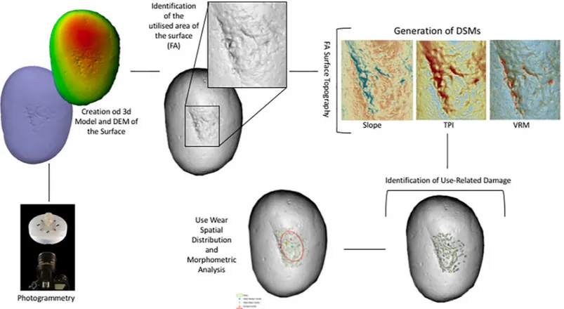
Fig 3. Schematic representation of the methodology applied for the creation of 3D models and the spatial analysis of the utilised areas of the tools.
Use wear analysis
The artefacts were analyzed applying a functional approach along with the design and applica-tion of a dedicated experimental framework. The funcapplica-tional approach is based on the analysis of different aspects related to the use of macro-lithic tools.
For the study, the specimens were observed utilizing a Zeiss Axio Zoom V16 binocular ste-reo microscope, oculars PI 10x/23, objective 1x/0.25 FWD 56mm, with progressive magnifica-tions ranging between 10x and 80x. This low-magnification observation allowed us to propose a hypothesis regarding the gestures and details related to the kinetics of the object. Further-more, it allowed us to determine the nature and status of the processed matter with which the object came into contact. Topography and microtopography, grain shapes, pits, striation and fracture morphologies on experimental and archaeological artefacts have been described according to parameters already described in literature [3,20]. 3D models of the surface were produced utilizing Mountain Map Premium 7.2, which provided more information related to the evolution of the microtopography and details concerning the morphology of the identified traces.
A second level of observation consisted of the analysis of the specimens at higher magnifica-tion (50-500x) using Zeiss Scope A.1 metallographic microscope equipped with 10x oculars and with objectives ranging from 5x to 50x. This allowed the investigation of micro wear (e.g. micro-striations and micro-polishes) to achieve more information about the use of the tools. Polishes have been described by taking into account their texture, topography, distribution, extension and linkage (for more details see [23,121,122]). The surfaces have been documented using a Zeiss Axiocam 305/506 color camera and were washed with neutro phosphate deter-gent (Derquim) and ultrasonic cleaner AU-32 (ARGO LAB) for 15/20m.
Photogrammetry
3D Models of both experimental and archaeological samples have been created through the application of photogrammetry. Following the protocol developed by Porter and colleagues [123] 3D models of the artefact were built using Agisoft Photoscan 1.3.4.
The tools were placed on an automatic turntable in order to produce 360˚ sets of each of the tool’s surfaces. Pictures of the tools were shot using a Nikon D7200 DSLR camera equipped with a Nikkor 105 Macro Lense. Each picture was taken every 15˚, and at every full revolution the camera was lifted and slightly titled towards the target for a total of 72 picture per object side. A total of 144 pictures were taken per object, which were subsequently imported in Agi-soft Photoscan Pro 1.3.4 to produce high quality dense point clouds and meshes.
Surface morphometric analysis
GIS analysis has been adopted to analyse the morphometric characteristics of both experimen-tal and archaeological samples. Applying both the methodologies proposed by Caruana et al [102], Benito-Calvo et al [103] and de la Torre et al [101] it has been possible to analyse and quantify use wear patterns originated from both retouching and percussive activities. After the creation of 3D Models, Digital Elevation Models (DEM) featuring a resolution of 0.5mm were created in Agisoft Photoscan 1.3.4 and imported as raster files in ArcGIS 10.5.
Digital Surface Models were generated in order to analyse the topographic features charac-terising the tool’s surface. At first a Hillshade model of the entire surface was created. This allowed a first morphometric assessment of the surface topography that permitted the identifi-cation of the Functional Area/s (FA) of the surface which are affected by use.
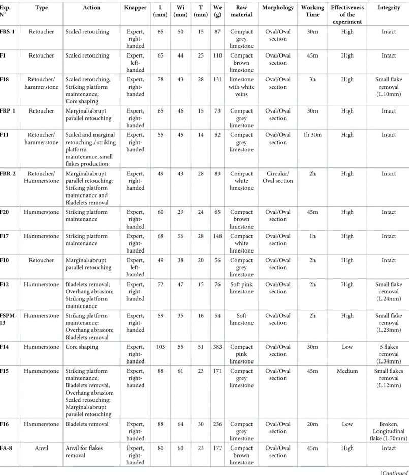
Table 2. List of experimental samples used in different phases of the chipped tools production. Exp.
N˚
Type Action Knapper L
(mm) Wi (mm) T (mm) We (g) Raw material Morphology Working Time Effectiveness of the experiment Integrity
FRS-1 Retoucher Scaled retouching Expert, right-handed 65 50 15 87 Compact grey limestone Oval/Oval section 30m High Intact
F1 Retoucher Scaled retouching Expert, left-handed 65 44 25 110 Compact brown limestone Oval/Oval section 45m High Intact F18 Retoucher/ hammerstone Scaled retouching; Striking platform maintenance; Core shaping Expert, right-handed 78 43 28 131 limestone with white veins Oval/Oval section
3h High Small flake removal (L.10mm) FRP-1 Retoucher Marginal/abrupt parallel retouching Expert, right-handed 65 46 15 73 Compact grey limestone Oval/Oval section 30m High Intact F11 Retoucher/ hammerstone
Scaled and marginal retouching / striking platform maintenance, small flakes production Expert, right-handed 55 45 14 52 Compact grey limestone Oval/Oval section 1h 30m High Intact FBR-2 Retoucher/ Hammerstone Marginal/abrupt parallel retouching; Striking platform maintenance and Bladelets removal Expert, right-handed 49 43 28 83 Compact white limestone Circular/ Oval section 2h High Intact
F20 Hammerstone Striking platform maintenance Expert, right-handed 60 29 24 65 Compact brown limestone Oval/Oval section 45m High Intact
F17 Hammerstone Striking platform maintenance Expert, right-handed 68 56 28 148 Compact white limestone Oval/Oval section 1h High Intact F10 Retoucher Marginal/abrupt parallel retouching Expert, left-handed 49 38 20 56 Compact grey limestone Oval/Oval section 2h High Intact
F12 Hammerstone Bladelets removal; Overhang abrasion; Striking platform maintenance Expert, right-handed 72 47 15 76 Soft pink limestone Oval/Oval section
2h High Small flake removal (L.24mm)
FSPM-13
Hammerstone Striking platform maintenance; Overhang abrasion; Bladelets removal Expert, right-handed 59 35 16 54 Soft limestone Oval/Oval section
2h High Small flake removal (L.23mm)
F14 Hammerstone Core shaping Expert, right-handed 103 55 51 383 Compact pink limestone Oval/Oval section 30m Low 5 flakes removal (L.34mm) F15 Hammerstone Striking platform
maintenance; Bladelets removal; Overhang abrasion; Scaled retouching; Marginal/abrupt parallel retouching Expert, right-handed 88 61 23 171 Compact grey limestone Oval/Oval section
45m Medium Small flakes removal (L.12mm)
F16 Hammerstone Bladelets removal Expert, right-handed 88 64 30 236 Compact grey limestone Oval/Oval section 20m Low Broken, Longitudinal flake (L.70mm) FA-8 Anvil Anvil for flakes
removal Expert, right-handed 80 60 23 177 Compact brown limestone Oval/Oval section 45m High Intact (Continued )
Once identified, the FA of the tool was extracted from the original DEM as a new raster sur-face and three kinds of Digital Sursur-face Models (DSMs) were generated to identify and interpret use wear.
Slope, which identifies the rate of change in the z-value from each of the cells composing a raster surface allows the identification of changes in the surface elevation such as depressions or pits characterising the objects FA. Subsequently, two DSMs devoted to the analysis of sur-face roughness were generated. Analysing sursur-face roughness permits the analysis of the degree of homogeneity or heterogeneity characterising the tool’s surface. As already stated by Benito-Calvo and colleagues (2015) the measurement of surface roughness can lead to the identifica-tion of polished areas (low roughness) generated by use. Two methods of surface roughness measurement have been applied:Terrain Ruggedness Index (TRI) and Vector Ruggedness Mea-sure (VRM). TRI is based on the algorithm proposed by Riley and colleagues [124] and calcu-lates the sum change in elevation between a grid cell and its neighbourhood. In the resulting DSM, a TRI value of 0 represents the minimum degree of roughness (i.e. homogeneous sur-face).Vector Ruggedness Measure (VRM) measures roughness as the dispersion of vectors
orthogonal to the surface within a specific neighbourhood. This method captures variability in slope and aspect into a single measure. A value of 0 represents no terrain variation (or lowest roughness) while a value of 1 represents a complete terrain variation (maximum roughness). In the case of the experimental replicas, 3D models and resulting DSMs were made before and after use. This allowed the mapping and quantification of the degree of variation in surface topography related to each of the experimental activities performed.
Following the methodological framework proposed by Caruana et al [102] the FAs of both experimental and archaeological implements were analysed through Topographic Position Index in order to identify areas of high micro topographic roughness coinciding with use related damage.
Topographic Position Index (TPI) is an elevation residual analysis which is applied to
iden-tify depressions and ridges affecting the artefacts surface topography [103]. The DSM gener-ated is based on the computation of the difference between the elevation of a cell and the mean elevation in a neighbourhood surrounding that cell. Neighbourhood mean elevation is calcu-lated using a moving window centred on the cell of interest. TPI positive values indicate that the cell is higher than its neighbourhood while negative values indicate the cell is lower, corre-sponding to either ridges and depressions. Hot Spot Analysis (Getis-Ord GI�) was performed on the generated surface in order to identify clusters of pits and ridges highlighted by TPI and corresponding to wear caused by use. The patterns identified through Hot Spot Analysis Table 2. (Continued)
Exp. N˚
Type Action Knapper L
(mm) Wi (mm) T (mm) We (g) Raw material Morphology Working Time Effectiveness of the experiment Integrity
F19 Hammerstone Bladelets removal Expert, right-handed 52 67 33 193 Soft pink limestone Oval/Oval section
45m High Flakes removal (L.50mm)
F3 Hammerstone Striking platform maintenance; Overhang abrasion Expert, right-handed 63 38 20 57 Soft pink limestone Oval/Oval section 30m High Intact FAR-8 bis
Anvil Anvil for bladelets retouching Expert, right-handed 80 64 30 236 Compact grey limestone Oval/Oval section 30m Low Intact
F20 Retoucher Edge abrasion Expert, right-handed 60 50 30 200 Compact grey limestone Oval/Oval section 25m High Intact https://doi.org/10.1371/journal.pone.0207773.t002
(Getis-Ord GI�) were then transformed into polygons, which provided metric data (e.g. area, perimeter) to be statistically compared (Fig 3).
Experimental framework
A dedicated experimental reference collection was necessary in order to understand the use of macro-lithics at Fumane cave, and to isolate specific gestures involved in percussion activities. The experimental framework consisted of different stages. Raw materials were collected according to the size and morpho-metric features of the archaeological specimens. Small and rounded pebbles (mean length 50 mm) of compact limestone were gathered along the Adige river bank, about 20 km away from Fumane. Coarse limestone pebbles were collected in a stream bed close to the site. The latter showed a pink/white colour, probably due to geochemi-cal alterations related to the particular depositional environment.
The collected items (5 retouchers, 3 retouchers/hammerstones, 9 hammerstones, 2 anvil) were used in several experimental tests) and their surface was documented using both the ste-reo and metallographic microscopes before and after their use, in order to observe the modifi-cations caused by use.
After a preliminary observation of the archaeological sample, it became clear that the Fumane macro-lithics had been used in various activities related to the processing of stone and materials of a non-organic nature. The experimental framework involved 19 pebbles used as hammers in various stages of bladelet production and retouchers, according to the technical solutions known from the analysis performed on the lithic artefacts from the Protoaurignacian and Aurignacian levels of the site, in which core reduction and maintenance are illustrated along with the morpho-technical features of the laminar products and the typology of the retouched tools [110,111,115,120].
For our experimental purposes, nodules of fine-grained flints were used. Several tests have been performed by the flint-knapper, following a precise strategy: a single hammer has been used to perform a specific action with the aim of isolating the functional traces, while others have been involved in different technical gestures to produce experimental replicas showing multi-functional surfaces (a complete list of uses has been illustrated inTable 2).
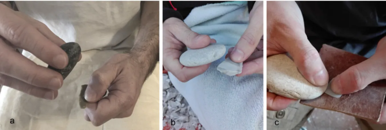
Gestures have been described following the criteria outlined by Bourguignon [78]. The fol-lowing points aim to explain the different phases and the relative technical gestures performed by the expert knapper during the experimental activities:
Fig 4. Experimental retouching. (a) Production of marginal and abrupt retouch; (b) production of scaled retouch on the lateral edge of a laminar flake; (c) blank retouch through edge abrasion.
Fig 5. Schematization of the gestures used during the retouching experimental activity. (a) The marginal and abrupt retouch: a rapid and consequential gesture was performed. The knapper’s arm moved following an oblique dragging trajectory against the blank’s edge, striking it very quickly using the tool’s flat face along the apical area; (b) the scaled retouch: this action followed a perpendicular trajectory, with respect to the blank edge, with a movement from the top to the bottom of the arm and a final flexion downwards(drawings by Giulia Formichella).
https://doi.org/10.1371/journal.pone.0207773.g005
Fig 6. Experimental bipolar percussion and retouch on anvil. (a) Bipolar percussion for flake production; (b) hinged laminar flake retouch on anvil adopting a rectilinear trajectory; (c) bladelet retouch on anvil adopting an oblique trajectory.
https://doi.org/10.1371/journal.pone.0207773.g006
• cortex removal and core-shaping. The soft stone hammers (103x55mm, average dimensions) were used for opening of the nodules to remove cortical flakes in order to shape a pre-form core composed of a single flaking surface related to a single striking platform. During this step, the hammer’s marginal ends have been used as active parts, performing a punctual ges-ture consisting of a wide rectilinear trajectory of the arm, related to the force necessary to remove larger products. Despite their effectiveness in flake detachment (cortical and non-cortical), they broke after a reduced number of blows (conchoidal fracture along the func-tional end or straight fracture following the percussion axis). Therefore, their use during this stage was evaluated as not functional;
• flaking surface and striking platform configuration. After having designed the core volume, the soft hammers (50x50mm, average dimensions) were used to open a flaking surface and prepare the platform and the flaking angle through tiny flake removal. During this phase, flakes of various sizes were removed alternating with abrasion of the overhang performed with the same hammer. This latter action required consequential and rapid gestures with resting percussion, aimed to remove micro-flakes from the overhang. This resulted in a more continuous action that involved a wide contact area–usually along the flat axis or
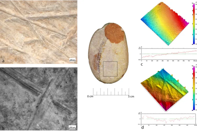
Fig 7. FSPM-13 use wear on experimental replica used in overhang abrasion. (a) Macro-traces (30x) long, deep striations alternate with more superficial striations, with different orientations. They are located on the flat and/or on the long edge of the instrument; (b) micro-traces (200x), striations with polishes on the bottom, with rough texture; (c) 3D microtopography of the unused surface and profile; (d) 3D microtopography of the used surface and profile.
lateral along the pebble edge–between the hammer and the core face. Removals of larger maintenance flakes required slower and more precise blows with a curvilinear trajectory, variable amplitude and force related to the size of the desired flake to be removed. This action involved the use of the marginal ends of the pebble along the minor axis;
• blank production and core maintenance. After having shaped the core, we proceeded to the extraction of lamellar blanks using an organic hammer (deer antler; [120], p.133) and a soft stone hammer, as hypothesized in a recent revision of the bladelets’ technical attributes ([111] p.27). During this phase, the stone hammers (sized 50-40mm in length, average dimensions) were always used with a rectilinear trajectory on their marginal ends. They per-formed effectively in blade production, even though small conchoidal fractures appeared in the functional area which, however, did not lead to discarding the tool. Flake detachment and abrasion operations were also carried out, aimed at maintaining the flaking angle and the transverse and longitudinal convexities of the core;
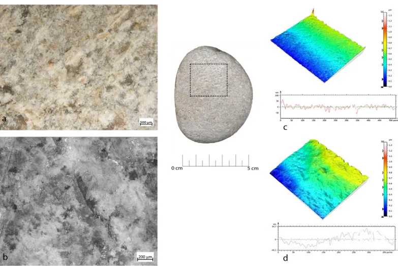
• bipolar percussion. Due to the presence of some splintered pieces in the archaeological assemblage ([120], p.139) we tested the bipolar percussion by placing the core on a base, Fig 8. FBR-2 use wear on an experimental replica used in the configuration of the striking platform of the core. (a) Macro-traces (30x) highlight the presence of overlapping pits with sub-oval morphology, located all around the marginal perimeter of the object; (b) micro-traces (200x) are extended onto the top of the grains, with smooth texture, flat topography, striation with the same orientation, and concentrated-separated distribution; (c) 3D microtopography of the unused surface and profile; (d) 3D microtopography of the used surface and profile.
https://doi.org/10.1371/journal.pone.0207773.g008
consisting of a large flat pebble selected among the collected items. At this stage, the core was of very reduced size and allowed the application of this technique despite the small size of the anvil (50x50x30 mm, average dimensions);
• retouching. Several gestures have been tested according to the different morphologies and intensity of retouching documented for Protoaurignacian and Aurignacian levels at Fumane cave. The occurrence of retouch features was strictly combined with the gesture and the tech-nique, which involved different uses of the functional areas of the pebbles (e.g. short edge or flat face).
a. Direct percussion. A rapid and consequential gesture was performed: the knapper’s arm moved following an oblique dragging trajectory against the blank’s edge, striking it very quickly using the tool’s flat face along the apical area. This movement allowed the removal of tiny flakes and was particularly effective for delineating straight cutting edges with marginal and abrupt retouch on thinner edges, due to the limited contact area between the hammer and the blank edge of a wide spectrum of blank morphologies from simple flakes to blades sharing a consistent thickness (Figs4Aand5B). We noted that this type of retouch can also be performed with different trajectories (e.g. perpendicular Fig 9. FA-8 use wear on experimental replica used in passive percussion. (a) Macro-traces (40x) consisted of large pits with sub-quadrangular/triangular morphology, grains appeared fractured, located in the central area of the flat surface of the pebble; (b) the micro-traces (200x) are absent, the bottom of the pits appear rough; (c) 3D microtopography of the unused surface and profile; (d) 3D microtopography of the used surface and profile.
to the blank axis). This technique was also used to delineate the front of carinated end-scrapers and of some thin end-scrapers, even though the short edge of the retoucher was used. This allowed the removal of tiny bladelets and elongated flakes by adopting a mar-ginal percussion (cfr. [125]). A more punctual gesture produced a more invasive retouch of a scaled type (Figs4Band5A), due to a larger contact area between the hammer flat face and the blank to be retouched. This action followed a perpendicular trajectory, with respect to the blank edge, with a movement from the top to the bottom of the arm and a final flexion downwards. This type of retouch has been performed on blades for delineat-ing the front of the end-scrapers (cfr. [111,120]).
b. Direct percussion on anvil (Fig 6). This technique was aimed at retouching tiny blade-lets: a flat pebble was used as anvil on which the blank edge was modified through the use of a retoucher by percussion ([98,126,127]). The trajectory was found to be variable depending on the position of the blank to be retouched on the anvil: in a central position a perpendicular trajectory was adopted, while when slightly inclined in proximity of the lateral edge of the anvil an oblique trajectory was adopted. In both cases, the short edges of the retoucher were used.
Fig 10. FRS-1 use wear on experimental replica used in scaled retouch. (a) Macro-traces (30x), contiguous pits of linear form (half-moon), with rough bottom, and triangular section; the traces are located in the centre of the apical area; (b) polishes (200x) are absent; (c) 3D microtopography of the unused surface and profile; (d) 3D microtopography of the used surface and profile.
https://doi.org/10.1371/journal.pone.0207773.g010
c. Edge abrasion (orégrisage, [127]). The bladelet edge was modified by rubbing against the pebble with the aim of delineating a straight edge (Fig 4C). This reciprocal contact permitted the detachment of micro-flakes.
Results
The replicas used during the experimental protocol comprised: a) hammerstones, used for removing cortex and shaping cores, abrasion of core edges and detachment of flakes and bla-delets (n.9); b) retouchers, used to produce different types of retouch (n.5); c) anvil, used as a passive base for detaching flakes (n.2); hammerstones/retouchers used with mixed activity (n.3).
Hammerstones
The types of use-wear observed on the hammerstones were:
• during cortex removal and core-shaping large longitudinal flake scars (50mm) located along the short edge were produced. In association with these scars there were residual surfaces Fig 11. FRP-1 use wear on experimental replica used in marginal retouch. (a) Macro-traces highlight area characterized by a concentration of micro-pits (25x) with sub-circular morphology; (b) long striation (20x) associated with the pits and with the same orientations; the traces are located in apical top with oblique orientation; (c) micro-traces (200x), band of polishes with striations, covered-closed distribution, rough texture and domed topography; (d) 3D microtopography of the unused surface and profile; (e) 3D microtopography of the used surface and profile (striations and pits).
with pits, similar to the deep scales, of around 6mm in size, with a triangular section. Micro-polishes were absent.
• Overhang abrasion activity produced long, deep striations alternated with more superficial striations, with different orientations, often associated with the configuration of the striking platform. These striations were located on the flat and/or on the long edge of the tool and showed polishing on the bottom with a rough texture when observed at the metallographic microscope (Fig 7).
Fig 12. List of experimental activity and use wear associated. Description of activities, macro and micro traces, use wear localisation and pictures.
https://doi.org/10.1371/journal.pone.0207773.g012
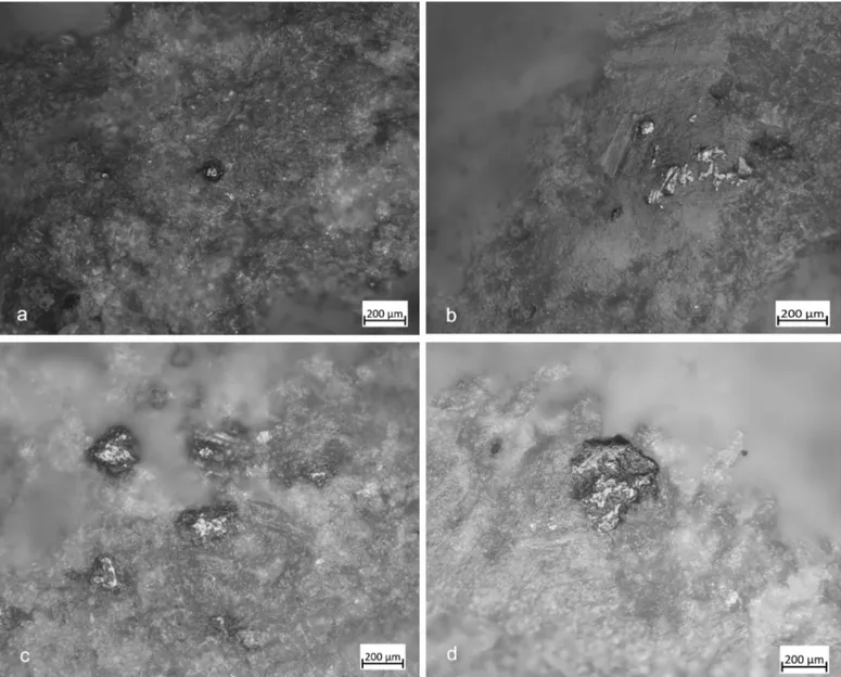
Fig 13. Experimental use wear related to the prehension. (a-b) Patch of polishing visible through the metallographic microscope (100x), localised on the top of the grain; (c-d) smooth/flat patch of polishing visible through the metallographic microscope (200x).
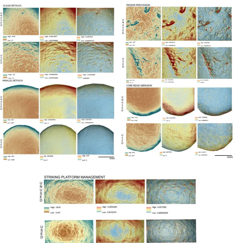
Fig 14. Comparison of the surface topography before and after the use of the tool to produce scaled and marginal retouch, percussion activities and bladelet production. Digital Surface Maps of Slope, TRI and VRM respectively.
https://doi.org/10.1371/journal.pone.0207773.g014
• During the configuration of the striking platform of the core, the removal of small flakes pro-duced small pits with sub-oval morphology. The pits often overlapped short superficial stria-tion. These traces were located on the short edges of the tool; if this is circular, use-wear traces were distributed all around its perimeter. A micro-polish was observed, extended on the top of the grains, with a smooth texture, flat topography, uniformly oriented striations, with concentrated-separated distribution (Fig 8).
• During blank production and core maintenance small sub-circular pits overlapping with small striations and chaotic orientation were produced; flake scars (20/30mm) due to the blow for the extraction of the blank were also observed. The mechanical levelling led to the production of short strips and sporadic polishing with loose-separated distribution on the top of the grains, with deep striation with the same orientation, and a rough texture and domed topography. The traces were located on the short edge of the hammerstone.
Pits produced by the trimming of the striking platform and the production of blanks and core maintenance looked very similar in their distribution and morphology. Often overlapping, pits were not well defined, but polishes looked different. In particular, the trimming of the striking platform produced polishing as a consequence of repeated contact between the hammer and the edge of the flint tool. On the contrary, the detachment of the blades/bladelets consisted of a more precise blow.
Bipolar percussion
Bipolar percussion makes large pits with sub-quadrangular/triangular morphology located in the central area of the flat surface of the tool. The texture grains appear fractured, polishes are absent (Fig 9).
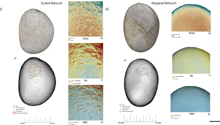
Fig 15. Experimental objects utilized for scaled retouch (I) and marginal retouch (II). (a) Spatial distribution of the identified wear; (b) slope; (c) terrain roughness index; (d) vector roughness measure.
Retouchers
Retouchers presented different types of use-wear. In detail, the scaled retouch generated a series of contiguous pits of a linear form (reduced half-moon) with a rough bottom and an asymmetric triangular section, localised on the flat surfaces of the tool concentrated near the apices. There were also striations: short, more sporadic and superficial (Fig 10). The micro-polishes were probably absent because the traces resulted from a punctual contact between the retoucher and the edge of the flint tool (the dragged gesture is absent).
Marginal retouch led to an association of small circular pits and dense long parallel stria-tions. Use-wear traces concentrated over the apical area of the flat surface, with oblique orien-tations. Bands of polishing with striations were present, with covered-closed distribution, a rough texture and domed topography. The dragging movement (oblique trajectory) related to the marginal retouch, produced a mechanical levelling of the surface where the polishes were present (Fig 11).
Other types of retouching were tested, including edge abrasion. This activity produced traces located in a small area between the short edge and the apical area of the retoucher. The traces consisted of small pits with sub-quadrangular morphology and short striations. The rough polishes were present.
Retouching on an anvil produced, on the passive base, superficial small pits with a sub-cir-cular morphology and short striation. The use wear was located on the flat surface. The pol-ishes were absent. The same traces were present on the active retoucher but located on the short edge (Fig 12).
Table 3. Morphometric features of the wear identified on the utilised areas of the experimental replicas. In detail, scaled retouch (FSR-1), marginal retouch (FRP-1), bipolar percussion (FA-8), striking platform maintenance (FSPM-13) and bladelet removal (FBR-2).
FRS-1 FRP-1 FA-8 FSPM-13 FBR-2 Perimeter (mm) Minimum 3.5 3.2 3 2.9 1.6 Maximum 34 21 28 74 22 Average 8.6 9 7.2 14 3.8 Area (mm2) Minimum 0.5 1 1 1 1 Maximum 6.7 5 9 17 5 Average 1.5 1 1 3 1
Distance from Centre (mm)
Minimum 7.6 9.7 0.1 11
Maximum 26 21 18 33
Average 16 15 9 20
Distance from Edge (mm)
Minimum 4.1 8.1 12 1.8
Maximum 21 18 27 20
Average 12 12 21 10
Standard Deviational Ellipse
Perimeter (mm) 52 38.8 61 63 43.2 Area (mm2) 216 106 281 311 116 Elongation (ad) 0.87 1.7 0.7 1.2 2.3 Used Area (%) 3 1 3 6 2 Pits Density (mm2) 0.02 0.01 0.02 0.02 0.02 https://doi.org/10.1371/journal.pone.0207773.t003
On the experimental samples, prehension traces were visible at high magnification. Macro-scopically, the prehensive area was smoothed, with several patches of smooth/flat polishing, affecting the top of the grains. Polishes visible between 20x and 50x developed on the flat and central portion of the tool, favoured by a type of prehension in which a large portion of the fin-ger (finfin-gertip) was in contact with the flat surface of the tool. Polishing was not observed in cases where the hammer or the retoucher was gripped by the short margins (tridigital prehen-sions) and the contact occurred with a reduced portion of the finger (Fig 13).
GIS analysis—Experimental sample
Overall, the raw material characterising the experimental sample presented in this work was homogeneous. This led to minimal modifications of the tools surfaces in particular concerning their roughness. On the other hand, the analysis of slope revealed several differences between the activities performed (Fig 14).
The experimental replicas utilised to produce scaled retouch recorded the development of depressions exhibiting a mean slope value of 9.94˚. Surface ruggedness measured through TRI and VRM appeared low with a mean TRI value of (0.0015) and a VRM mean value of (0.001). Fig 16. Experimental object utilized in passive percussion (I) and core ridge adjustment (II). (a) Spatial distribution of the identified wear; (b) slope; (c) terrain roughness index; (d) vector roughness measure.
Most of the variability was concentrated over the apices of the tool. Scaled retouch (Fig 15I,
Table 3) led to the development of use-related wear on the apical portion of the tool. Wear fea-tures were characterised by an average perimeter and an area of 8.6 mm and 1.5 mm2 respec-tively. The average distance of the wear feature from the centre of the tool was 16 mm while the average from its edge was 13 mm. Traces are concentrated over the central portion of the tool apex as suggested by the standard deviational ellipse elongation value (0.87 ad). As in the case of scaled retouch, use wear generated by marginal retouch (Fig 15II,Table 3) also affected the apical portion of the retoucher. The depression caused by use featured a slope mean value of 18.8˚. The surface showed an overall homogeneity as indicated by the recorded TRI (0.0015) and VRM (0.0023) mean values, with most of the surface variability localised on the tool apical areas. Use related wear exhibited an average perimeter of 9 mm and a mean area of Fig 17. Experimental object utilized for bladelet production. (a) Spatial distribution of the identified wear; (b) slope; (c) terrain roughness index; (d) vector roughness measure.
https://doi.org/10.1371/journal.pone.0207773.g017
Fig 18. Perimeter of the wear. (a) Dimensions of the wear identified over the utilized areas of the experimental replicas; (b) mean distance of the identified wear from the object centre; (c) mean distance of the identified wear from the object edge; (d) dispersion of the identified wear over the tool surface defined by the elongation of the standard deviational ellipse.
1 mm2along with an average distance from the tool centre and edge of 15 mm and 12 mm respectively. Traces generated by marginal retouch were well spread over the retoucher apical portion as suggested by the standard deviational ellipse elongation value (1.7 ad), higher than the value observed on the experimental replica used in scaled retouching.
Passive percussion (Fig 16I,Table 3) led to the development of wear over the central area of the tool used as anvil, where depressions developed featuring a mean slope value of 11.2˚. The surface was overall homogeneous (TRI mean value 0.007) with a low topographic variabil-ity (VRM mean value 0,0009) mostly at the bottom of the produced wear. Use marks generated by passive percussion featured a mean perimeter of 7.2 mm and an average area of 1 mm2. Traces were localised near the centre of the tool, with an average distance from the centre of 9 mm, while their average distance from the edges averaged 21mm. Traces were concentrated on the tool surface centre as indicated by the standard deviational ellipse elongation value of 0.7 ad.
Adjustment of core ridges (Fig 16II,Table 3) led to the development of use wear over the apical portion of the tool and in a minimal part over its inner areas. Depressions caused by use featured a mean slope value of 14˚, while the TRI and VRM mean values, 0.0011 and 0.0034 respectively, suggest an overall homogeneous surface topography with its higher topographic variability localised over the outer portion of the tool apical area. Marks generated by use were relatively large given their average perimeter of 14 mm and mean area of 3 mm2. While the inner area of the object was also affected, most of the traces generated by the adjustment of Table 4. Archaeological sample and use wear description and interpretation.
Id Type Activity Macro traces Micro traces Traces Localisation Prehension Note RF73 Hammerstone Core
maintenance and overhang abrasion
Isolated striations, chaotic, deep and long; overlapping pits.
Absent Pits located on short margins; striations on the flat surfaces
Absent The sample is altered (grain detachment and rounding) RF127 Hammerstone and Retoucher Core maintenance and scaled retouch
Small pits, overlapping with associated small striations; linear (half-moon) pits.
The bottom of linear pits is not polished
Pits overlapping located all around the short margin; linear pits located on the two flat surfaces
Yes, in the central area, on the flat surface (rounding of grain, organic film, and patches of polish) RF67 Retoucher Scaled retouch Linear (half-moon) pits The bottom
of linear pits is not polished
Pits located on the two flat surfaces, opposite apices
Absent Ochre residues; General rounding RF92 Anvil and retoucher Marginal retouch; passive anvil
Long, superficial striations with the same orientation, associated with small circular pits; pits with sub-triangular or quadrangular morphology. The bottom of the striations is not polished
Pits and associated striations located along the apices of the flat surfaces; pits with sub-triangular/quadrangular morphology in the central area on the flat surface
Absent
RF80 Retoucher Marginal retouch
Circular pits and associated striations on the apical areas of the flat surface
The bottom of the striations is not polished
On the apical areas of one flat surface
Absent
RF138 Hammerstone Bladelet removal Flake detachment and overlapping pits.
Morphology of the pits is not defined.
Polishing not present
Along the short, opposing, edges Absent Alterations, general rounding RF37 Hammerstone Overhang abrasion and percussion activity
There are long and deep striations and overlapping pits
Absent Striations on one of the flat surfaces; and sporadic pits on a long margin
Absent Alteration due to thermal contact; general rounding
https://doi.org/10.1371/journal.pone.0207773.t004
core ridges were located near the tool edge (average distance 10 mm) rather than its centre (mean distance 20 mm). Use related damage was well spread over the affected area of the tool as indicated by the standard deviational ellipse elongation value of 1.2 ad.
For the purpose of bladelets production (Fig 17,Table 3), the short edge of the experimen-tal replicas was used rather than its surface. Over the used portion the depressions generated by use were characterised by an average slope value of 23.7˚. The used area of the tool was characterised by a higher degree of heterogeneity when compared to the other experimental samples presented in this work, as indicated by TRI (mean value 0,0025) and VRM (mean value 0,0067). Of particular interest is the fact that surface roughness was lower in proximity to the centre of the used surface area, where the bigger traces were located. Wear generated by bladelets production featured an average perimeter of 3.8 mm and a mean area of 1 mm2. Damage affected most of the used area of the tool as indicated by the standard deviational ellipse elongation value (2.3ad) (Fig 18,Table 3).
Archaeological sample
Use wear analysis. In the archaeological sample, traces of use were identified on 7 objects. These allowed the determination of the use of the tools at Fumane cave as: a) hammerstones Fig 19. Use wear identified on artefact RF127. (a) Macro-traces (25x), overlaid pits with sub-circular morphology; (b) macro-traces (10x), pits located around the short edge of the artefact; (c) 3D microtopography of the used surface and profile.
(n. 3, RF37, RF138, RF73); b) retouchers (n.2, RF80 and RF67); c) hammerstone/retoucher (n.1, RF127); anvil/retoucher (n.1, RF92). The artefacts showed a general rounding due to post-depositional alteration, probably of chemical nature. Invasive patinas or concretions were visible in one case (RF73 around the edge) (Table 4).
Hammerstones. In four cases (RF127, RF73, RF138, RF37) pits and flake scars were local-ized on the short edges of the tool, namely on the opposing short margins or, if the instrument presents a sub-circular shape, all around its perimeter. Small pits overlapped, often associated with short and chaotic striations (RF127) (Fig 19). Polishing was not present, probably due to the overall rounding of the surface caused by post-depositional alterations. For the same rea-son, the pits morphologies were not well defined. However, they shared characteristics similar to those observed on wear produced during core maintenance, related to the detachment of small flakes observed during the experimental knapping of bladelets. One hammerstone (RF138) was characterised by pits associated with negative flake scars (average dimensions 25mm) localised on the short edge of the tool. Deep, long striations were localised on the flat surface, or on the long edge (RF73 and RF37). The flake scars looked very similar to the experi-mental ones produced during bladelet removal and in overhang abrasions during core man-agement. In one case (RF73) there was an association between the pits, in the marginal extremities, and long and deep striations on the flat surface (Fig 20). Moreover, on RF127 Fig 20. Use wear identified on artefact RF73. (a) Macro-traces (20x), long striations with different orientations located on the flat surfaces in the central area; (b) pits (20x) on the marginal surface, overlapping, covered by the patina. The artefact is affected by dissolution; (c) 3D microtopography of the used surface and profile. https://doi.org/10.1371/journal.pone.0207773.g020
polishing was observed associated with intense rounding of the grains over the central area of the flat surface. These latter patches of polish, affecting the top of the grains were characterised by a flat topography and a smooth texture similar to that observed on the experimental sample and related to prehension (Fig 21).
Anvil. Artefact RF92 featured pits with sub-triangular morphology over its central area. These had a rough bottom with microcracks visible over the grains. Polishing was not present. The observed functional patterns were similar to the experimental sample used as a passive anvil for flake detachment (Fig 22).
Retouchers. Macro-traces observed at the stereo-microscope were represented by pits and striations. However, the pits displayed differences in morphology and location. In two cases (RF67 and RF127) the pits were located on the apices opposite to the flat surfaces (on one or both surfaces). The morphology of the pits was linear (reduced half-moon), with a triangu-lar section. Polishing was not present (Figs23and24).
In two other cases (RF80 and RF92) (Fig 25) pits were always located on the flat surfaces of the tool over the apices and were characterized by circular morphology, associated with the presence of long, parallel, superficial and overlapped striations. These traces were very similar to ones observed in the experimental replica used for marginal retouching.
Fig 21. RF127b archaeological sample with intense rounding of the grains over the central area of the flat surface. (a) Polishing (100x) affecting the top of the grains; (b) patch of polish characterised by a flat topography and smooth texture (200x).
GIS analysis—Archaeological sample. As in the case of the experimental replicas, the raw material characterising the archaeological specimens presented in this work was of a homogeneous nature overall.
Specimen RF67 was interpreted through use wear analysis as likely to be a retoucher used to produce scaled retouching based on the presence of traces of use over its apical area, where depressions characterised by a mean slope value of 9.8˚ were present. The topography of the surface was homogeneous overall with a low to medium degree of surface roughness (TRI Fig 22. Use wear identified on artefact RF92. (a) Macro-traces (20x), micro-pits with sub-circular morphology associated with long parallel striations, located in the apical top with oblique orientation; (b) micro-traces (200x) are absent, a general rounding is visible; (c) macro-traces (20x), pits with triangular morphology, located in the centre area of the flat surface; (d) polishing is absent (200x); (e) 3D microtopography and profile of the used surface related to (a-b); (f) microtopography and profile of the used surface related to (a-b).
https://doi.org/10.1371/journal.pone.0207773.g022
mean value 0.00138) along with a low degree of topographic variation as indicated by the VRM mean value (0.0032). Wear generated by use featured a mean perimeter of 9 mm and mean area of 1 mm2. As observed on the experimental replica, use related traces were located towards the artefact edge (mean distance 12mm), while their average distance from the tools centre was 20mm. Wear results were well dispersed over the apical area of the retoucher as indicated by the standard deviational ellipse elongation value (1.6 ad).
Use wear identified on artefact RF80 (Fig 26II,Table 5) allowed us to interpret its function as a retoucher utilised for marginal retouching. As in the case of artefact RF67 (Fig 26I,
Table 5) wear was located over the apical area of the object, where depressions bearing a mean slope value of (13.8˚) were visible. The utilised area was characterised by a rough surface (TRI mean value 0.0021) becoming smoother towards the centre of the tool. The same pattern was evinced from VRM (mean value 0.0016), with a higher degree of topographic variation towards the outer portion of the tool apical area and lower values characterising its inner por-tion. This phenomenon can be explained by the fact that the outer area of the tool’s apex suf-fered a higher degree of surface crushing compared to its inner area. The traces observed on RF-80 were relatively small with an average perimeter of 2.8 mm and an average area of 0.33 mm2. Use related damage was localised nearer the edge of the retoucher (average distance 11 Fig 23. Use wear identified on artefact RF67. (a) Macro-traces (10x), contiguous pits of linear form (half-moon), with rough bottom and triangular section, located on the centre of apical area; (b) micro-traces (200x) are absent; (c) 3D microtopography of the used surface and profile.
mm) than its centre (mean distance 14 mm). Use wear appeared dispersed over the apical area of the tool as indicated by the standard deviational ellipse value (1.3 ad).
Two distinctive functional areas were identified on artefact RF92 (Fig 27I,Table 5), one localised at the centre of the object and one corresponding to its apical area. The wear identi-fied on each of the FAs was related to two different activities, passive percussion (RF-92a) and marginal retouching (RF92b). RF-92a was characterised by the presence of depressions with a mean slope value of 22.6˚, while more gentle slopes (mean value 15.6˚) characterised the depressions identified over RF92b. The surfaces of both the functional areas exhibited a medium to high degree of roughness, with RF92a exhibiting a TRI mean value of 0.0022 and RF-92b featuring a TRI mean value of 0.0029. A difference between the two surfaces was found in their topographic variability. While RF92a was characterised by a low VRM mean value (0.0008), with the higher values corresponding to the bottom of the traces generated by use, a higher variability characterised RF-92b (VRM mean value 0.0023) where higher values were spread over the entire used surface. Traces observed on the central area exhibited a mean perimeter of 7mm and an average area of 1mm2. The damage was located close to the centre of the tool (mean distance 10 mm) and were concentrated, as indicated by the standard devia-tional ellipse elongation value of 0.7ad.
Fig 24. Use wear identified on artefact RF127. (a) Macro-traces (30x), contiguous pits of linear form (half-moon), with rough bottom, located on the centre of apical area; (b) pits with rough bottom (200x); (c) 3D microtopography of the used surface.
https://doi.org/10.1371/journal.pone.0207773.g024
Use related damage identified on RF92b featured a mean perimeter of 7mm and an average area of 1 mm2. Traces were localised in proximity of the tool’s edge (average distance 12mm) and were dispersed over the utilised area (stde elongation 2 ad).
Use wear associated with the adjustment of the core ridges was identified over artefact RF73 (Fig 27II,Table 5). The utilised area of the tool was characterised by depressions bearing a mean slope value of 9.6˚. Overall the surface topography was characterised by a medium to high degree of roughness (TRI mean value 0.0021) along with a low to medium degree of topo-graphic variability (VRM mean value 0.0014). Traces related to use featured an average perim-eter of 7 mm and an average area of 1 mm2. Damage was localised near the artefact’s centre (mean distance 10mm) and was moderately dispersed over the used surface (stde elongation 1.3ad).
Three functional areas were identified on artefact RF127, corresponding to its apices (RF127a; RF127b) (Fig 28I,Table 5) and its short edge (RF-127c) (Fig 28II,Table 5). The wear identified on the apical area was associated with the production of scaled retouching, while the traces affecting its short edge were related to percussion activity involving the pro-duction of blank and core management. The apical area of the tool was characterised by a medium degree of surface roughness: TRI mean value 0.0015 (apical top) and TRI mean value 0.0021 (apical bottom). Both the apices were characterised by a low degree of topographic Fig 25. Use wear identified on artefact RF80. (a) Macro-traces (20x), small circular pits associated with long parallel striations, located in apical top with oblique orientation; (b) micro-traces (200x), polishing is absent, a general rounding of the artefact can be observed; (c) 3D microtopography of the used surface. https://doi.org/10.1371/journal.pone.0207773.g025
variability as indicated by the VRM mean values of 0.0012 (apical top) and 0.0011 (apical bot-tom). Use related damage affecting the top apical area featured a mean perimeter of 6.3 mm and an average area of 1 mm2. Similar dimensions were recorded within the traces located on the bottom apical area of the tool (average perimeter 6.7 mm and mean area 1 mm2). On both functional areas use related damage was dispersed over the surface as indicated by the recorded standard deviational ellipse value of 1.3 ad. The short edge of RF127 was instead characterised by slightly steeper depressions (mean value 20˚) compared to the ones observed over its flat surface. The topography of the surface was moderately rough (TRI mean value of 0.0021) with the lower values coinciding with the area of the edge mostly affected by use related damage. The surface topographic variability was low, given the VRM mean value of 0.0006. The traces identified on the short edge of RF127 exhibited a mean perimeter of 2.7 mm and an average area of 1 mm2. They appeared highly dispersed over the utilised surface, as indicated by the high standard deviational ellipse elongation value of 2.5 ad (Fig 29,Table 5).
Discussion
Through the application of a dedicated experimental framework we were able to test the usage, and suitability for the task, of different areas of the hammerstone or retoucher. Use wear analy-sis, performed at low and high magnification, permitted the definition of the morphological characteristics of wear associated with each of the performed activities. In the study of Fig 26. Archaeological items, RF67 (I) and RF80 (II), utilized in scaled retouching and marginal retouching. (a) Spatial distribution of the identified wear; (b) slope; (c) terrain roughness index; (d) vector roughness measure.
https://doi.org/10.1371/journal.pone.0207773.g026
archaeological samples from Fumane Cave, macro-trace analysis, performed at low magnifica-tion, resulted to be more indicative than the observation of micro wear at high magnificamagnifica-tion, due to the fact that in some cases chemical alteration had prevented the preservation of the micro traces. GIS analysis allowed the investigation of the macro-traces from a quantitative point of view, analysing aspects such as dimensions and spatial distribution of the wear gener-ated by each activity. Moreover, it permitted the collection of data concerning the topographic characteristics (e.g. slope, roughness and topographic variability) of the utilised area of the tool.
Overall, the dedicated experimental framework allowed the isolation of both qualitative and quantitative features concerning use wear deriving from both percussion and retouching activ-ities. The microscopic analysis of the surfaces provided qualitative aspects such as development of polish, micro-striations etc. GIS analysis revealed quantitative data (distance from centre, distance from edge and wear dispersion, this latter defined by the standard deviational ellipse elongation value) concerning the morphometry of use related damage associated to retouching activity, bipolar percussion and core maintenance activities.
Comparing the experimental and archaeological datasets provided positive results (Figs30,
31and32), supporting interpretation derived from use wear analysis. However, on this matter, a note of caution needs to be made. When the dimensions of damage were compared, those of the wear on the experimental replicas resulted to be much larger than those observed on the archaeological materials. This is due to the post depositional alteration affecting the archaeo-logical specimens and leading to an overall rounding and modification of the wear morphol-ogy, suggesting that dimensions alone cannot be considered as a diagnostic feature in the interpretation of tool use.
Table 5. Morphometric features of the wear identified on the utilised areas of the archaeological specimens.
RF-67 RF-80 RF-92 (a) RF-92 (b) RF-73 RF-127 (a) RF-127 (b) RF-127 (c) Perimeter (mm) Minimum 3.7 1.1 3.7 4 2.8 3.5 3.4 0.1 Maximum 18 10 32 14 26 13 10.5 17 Average 9 2.8 7 7 7 6.3 6.7 2.7 Area (mm2) Minimum 1 0.1 1 1 1 1 1 1 Maximum 4 1.5 10 2 6 2 2 4 Average 1 0.3 1 1 1 1 1 1
Distance from Centre (mm)
Minimum 13 9.2 2.4 26 0.4 9.5 12
Maximum 29 19 19.4 40 18 20 22
Average 20 14 10 32 9.5 16 17
Distance from Edge (mm)
Minimum 6 6 10 6 13 4.6 4.6
Maximum 18 15 26 19 33 16 14
Average 12 14 20 12 25 10 9
Standard Deviational Ellipse
Perimeter (mm) 42 27 69 50 65 32.7 29 42 Area (mm2) 130 55 372 170 330 81 64 180 Elongation (ad) 1.6 1.3 0.7 2 1.3 1.3 1.3 2.5 Used Area (%) 2 <1 1 1 1 <1 <1 4 Pits Density (mm2) 0.01 0.01 0.01 0.01 0.01 0.01 0.01 0.01 https://doi.org/10.1371/journal.pone.0207773.t005
Fig 27. Archaeological items RF92 (I) and RF73 (II) utilised in retouch and percussion activities (RF92) and core ridge adjustment (RF73). (a) Spatial distribution of the identified wear; (b) slope; (c) terrain roughness index; (d) vector roughness measure.
https://doi.org/10.1371/journal.pone.0207773.g027
Fig 28. Archaeological items RF127. The surface of the tool (I) has been used in retouch activities while its edge (II) was used to produce bladelets/core adjustment. (a) Spatial distribution of the identified wear; (b) slope; (c) terrain roughness index; (d) vector roughness measure.
Within the Fumane Cave macro-lithic sample, several implements exhibited use patterns resembling the ones recorded on the experimental replicas used in scaled and marginal Fig 29. Archaeological specimens. (a) Dimension of the wear identified over the utilized areas; (b) mean distance of the identified wear from the object centre; (c) mean distance of the identified wear from the object edge; (d) dispersion of the identified wear over the tool surface defined by the elongation of the standard deviational ellipse.
retouching. In particular, artefacts RF67 and RF127 have been interpreted as retouchers used for scaled retouching, while the apical area of artefact RF92 and RF80 exhibited use wear fea-tures which led to their interpretation as retouchers used to produce marginal retouching. On 4 archaeological artefacts coming from Fumane Cave, the presence of overlapping pits over the short edges of the tools (RF127, RF138) and of deep long striations affecting the flat surface of the implements (RF73, RF37) led to the interpretation of the artefacts as hammerstones used in both blank production and core maintenance activities. Wear patterns similar to the ones associated with bipolar percussion have been identified on the central surface area of arte-fact RF92 leading to the interpretation of the use of its central area as an anvil (Fig 33). Our results enabled the identification of specific functional patterns related to the use of hammer-stones and retouchers at Fumane Cave. We have been able to isolate specific patterns both regarding the morphology of the wear, its spatial distribution and the topography of the used area associated with each of the activities performed. This permitted the placing of the Proto-aurignacian and Aurignacian macro-tools of Fumane Cave into specific stages of the produc-tion process of chipped tools. Our analysis underlined the high efficiency of the Fumane cave Fig 30. Comparison between the perimeters of the wear observed on the experimental = green, and archaeological = blue specimens.
https://doi.org/10.1371/journal.pone.0207773.g030
Fig 31. Comparison between the mean distances from the centre and the edge of the tool observed on the experimental and archaeological specimens.
https://doi.org/10.1371/journal.pone.0207773.g031