Università degli Studi della Calabria
Dottorato di Ricerca in Ingegneria Chimica e dei Materiali
SCUOLA DI DOTTORATO " PITAGORA " IN SCIENZE INGEGNERISTICHE
Tesi
Preparation of Organic Solvent Resistant
Polymeric Membranes for Applications
in Non-aqueous Systems
Settore Scientifico Disciplinare CHIM07 – Fondamenti chimici delle tecnologie
Supervisori
Candidato
Ch.mo Prof. Enrico DRIOLI
Eun Woo LEE
Ciclo XXIV
Il Coordinatore del Corso di Dottorato
List of contents
Summary ··· I Sommario ··· IV Acknowledgements ··· VII
Chapter 1 An introduction on membrane technology ···1
1.1. Introduction ···1
1.2. Membrane and membrane separation ···3
1.2.1. Membrane materials ···3
1.2.2. Membrane structures ···4
1.2.3. Membrane modules ···6
1.3. Membrane processes ··· 10
1.4. Preparation of synthetic membranes ··· 13
1.4.1. Phase inversion ··· 13
1.4.1.1. Principle of membrane formation by phase inversion ··· 15
1.5. Influence of various parameters on membrane morphology ··· 21
1.6. Membrane characterization ··· 25 1.6.1. Morphological analysis ··· 25 1.6.2. Physicochemical parameters ··· 27 1.6.3. Performance parameters ··· 27 1.7. Transport mechanism ··· 29 References ··· 36
Chapter 2 Solvent resistant membranes ··· 41
2.1.1. Materials ··· 45
2.1.2. Commercial membranes ··· 48
2.1.3. Applications for industry ··· 51
2.1.3.1. Food applications ··· 51
2.1.3.2. Catalytic applications ··· 52
2.1.3.3. Petrochemical applications ··· 53
2.1.3.4. Pharmaceutical applications ··· 55
2.1.4. Transport models for SRNF membranes in non-aqueous systems ··· 55
2.2. Scope and outline of this study ··· 61
References ··· 64
Chapter 3 Porous PDMS membranes ··· 71
3.1. Introduction ··· 71
3.2. Experimental ··· 73
3.2.1. Materials ··· 73
3.2.2. Preparation of porous PDMS membranes ··· 75
3.2.2.1. PDMS/Alcohols system ··· 75
3.2.2.2. PDMS/Dioxane system ··· 76
3.2.3. Membrane characterization··· 77
3.3. Results and discussion ··· 78
3.3.1. PDMS/Alcohols system ··· 78
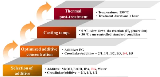
3.3.1.1. Screening of effective additives ··· 78
3.3.1.2. Effect of EG concentration ··· 79
3.3.1.3. Effects of temperature of casting solution and the thermal post-treatment ··· 81
3.3.2. PDMS/Dioxane system ··· 84
3.3.2.1. Effect of Dioxane content ··· 84
3.4. Conclusions ··· 90
References ··· 93
Chapter 4 Polyimide asymmetric membranes ··· 95
4.1. Introduction ··· 95
4.2. Experimental ··· 96
4.2.1. Materials ··· 96
4.2.2. Membranes preparation ··· 99
4.2.3. Membrane permeation experiments ··· 101
4.2.4. Membrane characterization··· 102
4.2.5. Ternary phase diagrams ··· 103
4.3. Results and discussion ··· 103
4.3.1. Effect of the polymer concentration ··· 103
4.3.2. Effect of the concentration of volatile co-solvent ··· 105
4.3.3. Permeation flux of pure solvents ··· 109
4.3.4. Effect of the ionic charge, molecular weight and solvent type on membrane rejection ··· 111
4.3.5. Effect of solvent type in the casting solution ··· 113
4.3.6. Effect of non-solvent additives ··· 118
4.3.7. Effect of different crosslinking conditions ··· 123
4.4. Conclusions ··· 127
References ··· 129
5.1. Introduction ··· 133
5.2. Experimental ··· 135
5.2.1. Materials ··· 135
5.2.2. Spinning of hollow fiber membranes ··· 136
5.2.3. Chemical crosslinking (post-treatment) and module preparation ··· 139
5.2.4. Characterization of hollow fiber membranes ··· 139
5.2.4.1. Membrane morphology and chemical/mechanical properties ··· 139
5.2.4.2. Nanofiltration test ··· 140
5.3. Results and Discussion ··· 142
5.3.1. Membrane morphology ··· 142
5.3.2. Chemical and mechanical properties ··· 145
5.3.3. Permeation properties ··· 149
5.4. Conclusions ··· 153
References ··· 155
Summary
Nowadays, membrane processes are used in a wide range of separation applications and the number of such applications is still rapidly growing. Since, today, environmental concerns have added impetus to the search for highly energy efficient and environmentally safe separation technologies. One of such technology which can meet these needs is the membrane separation, which offers significant reductions in energy consumption and eco-friend process in comparison with conventional separation techniques.
The membrane processes which can operate in liquid non-aqueous environments have grown not only in academic interests but also in industrial applications. However, the transport mechanism of molecules of solvents and solutes through the polymeric membranes in non-aqueous system is much more complicated than that of in non-aqueous system. In non-aqueous system, the physical and chemical interaction between membrane, solute and solvents has to be taken into account. Even the transport mechanism is not fully understand it should be noted, however, that the recent intensive study on the development of new membranes and materials has resulted in commercially available membrane for organic solvent nanofiltration (OSN).
This study is focused on the preparation and characterization of polymeric membranes for uses in non-aqueous system. Polymeric membranes were prepared from poly(dimethyl siloxane) (PDMS) or co-polyimide (P84, PI). To control the pore size and pore size distribution, optimum procedures and manufacturing parameters were established.
More detailed experimental conditions and results will be discussed in the following individual chapters.
Chapter 1 gives a general introduction on membrane and membrane process. In addition, the basic principles of membrane technology and theories necessary for understanding transport phenomena are discussed in this chapter.
In Chapter 2, more detailed background and review of literature on the organic solvent resistant membranes are discussed. Finally, clear scope and outline of this thesis will be covered in this chapter.
The fabrication and evaluation of the flat sheet poly(dimethyl siloxane) (PDMS) membranes are described in Chapter 3. Two different methods were used for the porous PDMS membranes. The first method was using chemical pore forming agent, alcohols (isopropanol, methanol, ethanol and ethylene glycol) and water, which can react with hydrogen molecule in crosslinker of PDMS to form hydrogen (H2) gas. Here, crosslinking speed of PDMS and reaction (H2 formation) and diffusion rate of H2 gas govern the structure and porosity of the membrane. The second method was using physical pore forming agent, 1,4-Dioxane, which was dispersed in PDMS solution then washed out after the film formation.
In Chapter 4, asymmetric P84® co-polyimide membranes in flat sheet configuration have been prepared and characterized. The effects of polymer concentration and solvent type on the performance and morphology of polyimide membranes have been intensively investigated. Furthermore, volatile co-solvent additive (1,4-Dioxane) and non-solvent
additives (water and ethanol) were used to prepare ternary mixture of casting solution and the effect on the membrane morphology and permeation properties were also investigated. The membrane performances were evaluated by organic solvents permeation experiments and rejection test using dyes which have different physical and chemical properties (molecular weight and charge).
The results evidenced that the morphology and also the membrane performances can be influenced by thermodynamic and kinetic effects during phase inversion process.
After membrane formation, to improve the chemical stability of the membrane, chemical crosslinking was conducted using 1,5-Diamino-2-methylpentane (DAMP). Crosslinking conditions were also optimized by controlling the concentration of crosslinker and crosslinking time. Creosslinked membranes were highly stable in numerous organic solvents including aprotic solvents (DMAc, DMF and NMP) in which the original polymer was soluble.
In Chapter 5, solvent resistant nanofiltration (SRNF) hollow fiber membranes were prepared from P84® co-polyimide by wet or dry-wet phase inversion methods. Furthermore, innovative in-line chemical crosslinking was carried out by introducing aqueous diamine (DAMP) solution as the bore fluid. Chemical and mechanical properties were analyzed by FT-IR/ATR and tensile strength measurement, respectively. In addition, permeation properties of the hollow fiber membranes were characterized by solvent flux and solute (Rhodamine B) rejection in acetonitrile and ethanol.
Sommario
Operazioni a membrana sono oggi usate in numerosi processi di separazione e il numero di applicazioni è in rapida crescita anche grazie alla necessità di sviluppare nuovi processi sempre più eco-sostenibili. Le operazioni a membrana sono infatti caratterizzate da una più elevata efficienza energetica e minore impatto ambientale rispetto ai processi tradizionali di separazione.
In particolare, è evidente un crescente interesse sia accademico che industriale verso processi di separazione a membrana in fase liquida non acquosa. Tuttavia i meccanismi di trasporto del soluto attraverso membrane polimeriche in ambiente organico, sono molto più complicati che in fase acquosa a causa delle forti interazioni fisiche e chimiche tra membrana, soluto e solvente.
Nonostante i meccanismi di trasporto non siano stati completamente chiariti, sono attualmente disponibili membrane commerciali per nanofiltrazione in solventi organici (OSN).
Questo lavoro ha avuto come obiettivo la preparazione e caratterizzazione di membrane polimeriche da impiegare in separazioni in solventi organici.
Sono state preparate membrane polimeriche a base di
polidimetilsilossano (PDMS) e un co-polimero della polimmide (P84, PI).
Al fine di controllare la dimensione e distribuzione dei pori, è stato investigato l’effetto dei diversi parametri di preparazione e i dettagli sperimentali sono forniti nei capitoli seguenti
Nel Capitolo 1 è presentata una introduzione generale sulle membrane e i processi a membrana.
Nel Capitolo 2 è presentata una overview sullo stato dell’arte delle membrane polimeriche per separazioni in solventi organici, con particolare attenzione alle membrane da nanofiltrazione (SRNF).
Nel Capitolo 3 è descritta la preparazione di membrane piane porose a base di PDMS. Due differenti metodi sono stati seguiti: nel primo, per formare i pori delle membrane, sono state usate specie chimiche quali acqua, iso-propanolo, metanolo, etanolo e glicole etilenico, che producono idrogeno gassoso in situ mediante reazione con i gruppi Si-H del crosslinker usato per preparare il PDMS (polimero formato da reazione di idrosililazione fra un pre-polimero e un crosslinker). Nel secondo metodo è stato usato l’1,4-diossano come additivo in grado di formare i pori successivamente alla sua rimozione dalla membrana.
Nel Capitolo 4, è stata descritta la preparazione e caratterizzazione di membrane asimmetriche piane della co-polimmide P84®. E’ stato studiato l’effetto della concentrazione del polimero e del tipo del solvente sulla morfologia e proprietà di trasporto delle membrane.
E’ stato inoltre investigato l’effetto della presenza di diverse concentrazioni di un co-solvente (1,4-diossano) o un non-solvente (acqua ed etanolo) nella soluzione polimerica.
Le proprietà di trasporto delle membrane sono state valutate in test di permeazione con solventi organici e di reiezione nei medesimi solventi con molecole modello quali coloranti a diversa massa molare e carica
stabilità, mediante reazione con 1,5-diamino-2-metilpentano (DAMP). Le condizioni di reticolazione sono state ottimizzate variando la concentrazione del reagente e il tempo di reazione. Le membrane reticolate sono risultate completamente stabili in numerosi solventi organici inclusi solventi come DMAc, DMF e NMP, in cui il polimero di partenza era solubile.
Nel Capitolo 5 è stata descritta la preparazione di fibre cave SRNF mediante inversione di fase indotta da non solvente, preceduta o meno, da una parziale evaporazione del solvente.
Inoltre è stata realizzata una innovativa procedura di reticolazione in cui durante la filatura il DAMP è stato introdotto nel fluido interno.
Le proprietà chimiche e meccaniche delle fibre sono state analizzate rispettivamente mediante FT-IR/ATR e test di elongazione. Inoltre sono stati condotti test di permeazione e reiezione usando la Rodamina B in acetonitrile ed etanolo.
Acknowledgements
The research leading to these results has received funding from the European Community's Seventh Framework Programme [FP7/2007-2013] under grant agreement n° ITN 214226 NEMOPUR.
Chapter 1 An introduction to membrane technology
1.1. Introduction
Membrane technology has been used in numerous industrial applications. Membrane separation processes provide the following advantages [1-4] compared to conventional separation processes like distillation, crystallization, extraction, absorption and adsorption;
1. Membrane processes, in general, do not require phase changes during the transfer across membrane (except membrane distillation). As a result, energy requirements are relatively low.
2. Flexibility in equipment design and operations because the membrane systems are modular. Depending on the requirements, it is possible to increase and/or decrease the number of membrane modules (membrane area) to achieve target goals in a given separation.
3. The modular design of membrane process provides a compact footprint which minimizes space requirement and lower maintenance costs as well.
4. Membrane processes are eco-friendly process since they do not generate any second pollutants and do not need any additional chemicals for separation.
5. Membranes can be produced with high selectivity for the components to be separated. In some application, these values are much higher than conventional processes.
6. Membrane processes are able to recover minor but valuable components from a main stream without substantial energy costs.
In order to develop successful membrane processes, all individual core R&D factors (shown in Figure 1.1) starting from the selection of an appropriate material to process optimization and evaluation, including economic analysis, should be well integrated and perfectly optimized. Especially, material selection and preparation of membrane and modules with the optimum separation characteristics are the most important part in the whole process.
Figure 1.1. Core R&D factors for development of successful membrane process.
1.2. Membrane and membrane separation
Although it is difficult to give an exact definition of a membrane, membrane can be defined as a selective or non-selective barrier that separates and/or contacts two adjacent phases and allows or promotes the exchange of matter and/or energy between the phases.
Separation through the membrane can be achieved by transporting certain component more rapidly than others by physicochemical affinity or interaction between membrane and species, applying appropriate driving forces such as concentration, pressure, temperature and electrical potential gradients, etc. [3].
1.2.1. Membrane materials
Membranes can be classified by their nature, i.e. biological or synthetic membranes [1]. Synthetic membranes are further subdivided into organic (polymeric), inorganic (ceramics, metals and glass) and liquids [4].
Inorganic membranes have several useful properties such as their high mechanical stability and elevated resistance at high operating temperature with superior chemical resistance [5]. The long-term stability at high temperature makes these materials very attractive for gas separation at high temperature, especially in combination with a chemical reaction where the membrane is used as catalysts as well as a selective barrier to improve conversion rate by removing one of the components produced by reaction (membrane reactor). However, despite these beneficial properties, the most utilized membrane material is still
polymeric, since inorganic membranes are fairly brittle and much more expensive with respect to the membrane area compared to membranes produced from organic materials. Furthermore, high capital cost and sealing problem at high temperature should be solved [3].
As mentioned above, most commercially available membranes are prepared from polymeric materials. Basically, all polymers can be used as membrane material but the physical and chemical properties differ so much that only a limited number will be used in practice. The polymer materials not only have to resist acids, bases, oxidants or reductants, high pressures and high temperatures, but also must have appropriate chemical properties for realizing high flux and high selectivity membranes for the various applications. Furthermore, with polymeric membranes good processability, inexpensive production and easy modular design can be obtained. Therefore, it is important to understand the polymer properties such as structural factors - chain flexibility, molecular weight and chain interaction - that determine the thermal, chemical and mechanical characteristics of polymers [4].
1.2.2. Membrane structures
Other than for the type of materials, with regard to the membrane morphology or structure, membranes can also be classified into symmetric and asymmetric membranes (Figure 1.2). Further, these classes can be categorized into porous and dense (non-porous) membranes.
The symmetric membrane can be cylindrical porous, porous and non-porous. The thickness of symmetric membranes ranges roughly from 10
to 200 µm. The structure and the transport properties of symmetric membrane are identical over the entire cross-section and the thickness of the entire membrane determines the flux [3].
The asymmetric membranes can be 1) porous, 2) integrally skinned or 3) composite, that is consisting of a porous support layer and a dense top selective layer. The asymmetric membranes refer to the formation of a thin (typically 0.1-1.0 µm in thickness) dense or porous layer which is bonded to a thick, porous substructure (100-200 µm in thickness). In asymmetric membranes, porous substructure provides mechanical strength of the membrane while the separation takes place in selective porous or dense layer. It should be noted that the integrally skinned membrane uses same material for selective (dense) layer and sublayer. However, in composite membranes, the selective layer and support layer originate from different materials and each layer can be optimized independently.
Most porous membranes had been developed for size-based separation of mixtures in liquid phase, driven by a pressure difference or concentration difference. Based on its pore size, a porous membrane should be classified into microfiltration (MF: from 1.0 to 0.05 µm), ultrafiltration (UF: from 50 to 2 nm) and nanofiltration (NF: less than 2 nm) [3, 6]. In a dense membrane, the separation occurs through fluctuating free volume and a mixture of molecules is transported by concentration or electrical potential gradient. Dense membranes are mainly used to separate components which have similar size but have different chemical/physical nature in process such as reverse osmosis (RO), gas separation (GS), vapor permeation (VP) and pervaporation
(PV).
Cylindrical porous Porous Non-porous (dense)
(a) Symmetric membranes
Porous skinned Integrally skinned Composite
(b) Asymmetric membranes
Figure 1.2. Schematic representation of various membrane structures.
1.2.3. Membrane modules
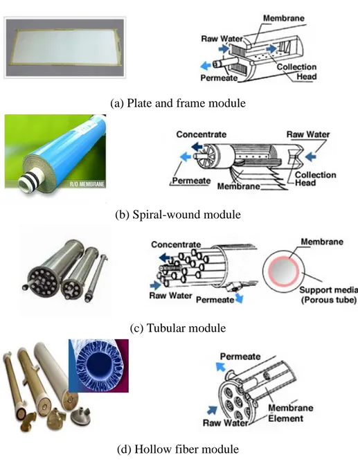
The membranes can be fabricated as flat sheets, hollow fibers or capillaries and tubular membranes. Then, in order to use the prepared membranes on a practical scale, large membrane areas are normally required. The smallest unit in which a certain membrane area is packed is called a module. Modules are the smallest, replaceable unit in a membrane system, and housed in any appropriate cartridge or vessel configuration. The most commonly used module configurations for industrial applications are illustrated in Figure 1.3 [1, 7].
Flat sheet membranes are mainly installed in plate and frame or spiral-wound module configuration. In plate and frame module, the membranes, porous membrane support plates, and spacers are clamped together and
stacked layer by layer. In this module configuration, the membranes can easily be changed and the housings and other components are made from stainless steel so that the module can be steam sterilized. It makes this module configuration suitable for pharmaceutical, bio products, or fine chemicals applications. However, this unit is relatively expensive and the change of the membranes is labor intensive.
Spiral-wound module is widely used today in reverse osmosis, ultrafiltration, and gas/vapor separation. Commercial modules are about 1 meter length and have a diameter of 10 to 60 cm. The membrane area of these spiral-wound elements is 3 to 60 m2 and 2 to 6 elements are placed in series in a pressure vessel. This module configuration provides a relatively large membrane area per unit volume. The large-scale production is quite cost effective and module cost per membrane area is quite low. Disadvantages of this module configuration are (a) quite sensitive to fouling, (b) the feed channels can easily be blocked, requiring additional care for pretreatment, and (c) the presence of spacer has a large influence on mass transfer and the pressure drop.
(a) Plate and frame module
(b) Spiral-wound module
(c) Tubular module
(d) Hollow fiber module
Figure 1.3. Schematic drawings and photos of various membrane module configurations.
In contrast to hollow fibers, tubular membranes are not self-supporting. Therefore, tubular membranes are placed into porous stainless steel or ceramic and fiberglass reinforced plastic pipes. The pressurized feed introduced through the bore and permeates are collected on the outer side of the porous support pipe. The main advantages of this module configuration are that concentration polarization and membrane fouling can be easily controlled. In addition, plugging of membrane module is avoided even with feed solution contains high concentration of solid matters or with high viscous systems. However, low packing density which leads to low membrane area and high cost remain a disadvantages.
The hollow fiber and capillary membrane modules have the highest packing density of all module configurations available on the market today. The diameter of the fibers varies over a wide range, from 50 to 3000 µm. Particularly, fibers with a diameter greater than 500 µm are called capillary fibers. Feed stream can flow through the lumen side (or inside) (inside to out) of the fiber or on the shell side (or outside) (outside to in). However, the main disadvantages of hollow fiber module configuration are the difficult control of concentration polarization and membrane fouling. Therefore, pretreatment processes are required and as a consequence main application of the hollow fiber membrane module configuration is in desalination of seawater, in gas separation and pervaporation in which the feed stream is relatively clean [1, 3].
Table 1.1 Advantages and disadvantages of module configuration [2, 8]. Module Chanel spacing (cm) Packing density (m2/m3) Energy costs (pumping) Particulate plugging Ease of cleaning Flat sheet 0.03-0.25 300 moderate moderate good
Spiral
wound 0.03-0.1 600 low very high poor-fair
Tubular 1.0-2.5 60 high low excellent
Hollow
fiber 0.02-0.25 1200 low high fair
1.3. Membrane processes
In the last few decades, numerous research papers have been reported on new membrane materials which have improved separation properties (high flux and high selectivity). These scientific efforts make that membrane operations can successfully substitute and/or integrate with conventional separation processes. In the early 1960’s, a major breakthrough was achieved by the development of high performance asymmetric cellulose acetate membranes by Loeb and Sourirajan [9].
Today, 50 years later, membranes and membrane processes have indeed become valuable tools for the separation of molecular mixtures.
Membrane processes can be classified according to the driving forces into [1, 3, 10];
1) Pressure: microfiltration (MF), ultrafiltration (UF), nanofiltration (NF), reverse osmosis (RO), gas separation (GS).
2) Concentration gradient: gas separation (GS), vapor permeation (VP), pervaporation (PV), forward osmosis (FO) [11], pressure retarded osmosis (PRO) [12-13], membrane contactor (MC) and liquid membrane (accompanying reaction).
3) Electrical potential: electro dialysis (ED), electro-osmosis, electrophoresis.
4) Temperature difference: membrane distillation (MD).
However, it should be noted that in many membrane processes more than one driving force can works at the same time, and all these parameters (pressure, concentration, etc.) can be expressed by the electro-chemical potential.
Now, membrane processes are extending their application in a wide range of industrial processes [10]. For instance, seawater and brackish water desalination using reverse osmosis and electrodialysis are energy efficient and highly economic processes for large-scale production of potable water. Micro- and ultrafiltration are used for the production of high-quality industrial water and for the treatment of industrial effluents. In addition, membrane processes have found a multitude of applications in chemical and pharmaceutical industries as well as in food processing and biotechnology. They are used on a large scale in gas separation, vapor permeation and pervaporation. The development of membranes with improved properties will most likely increase the importance of membranes and membrane processes in a growing number of applications for the sustainable growth of modern industrial societies.
Table 1.2 Classification of membrane process and their applications[3]. Separation process Membrane Type Driving force Method of separation Range of application Microfiltration symmetric macroporous, 0.1-10 µm pore radius hydrostatic pressure difference 0.1-1 bar sieving mechanism convection water purification, sterilization Ultrafiltration asymmetric macroporous, 1-10 µm pore radius hydrostatic pressure difference (0.5-5 bar) sieving mechanism convection separation of molecular mixtures Nanofiltration asymmetric mesoporous, 0.5-2 nm hydrostatic pressure (5-20 bar) sieving mechanism diffusion Donnan exclusion separation of molecular mixtures and ions Reverse osmosis integrally skinned asymmetric membrane or thin film composite (TFC) hydrostatic pressure (20-100 bar) solution-diffusion separation of salts and microsolutes from solutions Dialysis symmetric microporous, 0.1-10 µm pore radius concentration gradient diffusion in convention free layer separation of salts and microsolutes from macromolecular solutions Electro dialysis symmetric ion exchange membranes electrical potential gradient Donnan exclusion desalting of ionic solutions Gas and vapor
separation
dense homogeneous or
porous polymer
gas and vapor pressure solubility and diffusion, Knudsen diffusion separation of gas mixture, vapors and
isotopes Pervaporation dense homogeneous asymmetric vapor pressure solution- diffusion separation of azeotropic mixtures
However, an important issue in membrane technology is not only improving the transport properties but also to achieve a high physical, chemical and thermal stability. That is why among the available polymeric materials only few are used for the preparation of commercial membranes [14].
1.4. Preparation of synthetic membranes
To obtain a membrane structure with morphology appropriate for a specific application, several techniques have been used for preparation of synthetic membranes. The most important techniques are sintering, track etching, stretching and phase separation processes. In particular, for the preparation of polymeric membranes related to this study, the phase inversion method will be introduced in detail.
1.4.1. Phase inversion
‘Phase inversion’ refers to the process in which a homogenous solution of a polymer in a solvent (or solvent mixture) inverts from a single phase into a phase system by a demixing process. The two-phase system consists of a polymer-rich two-phase which will form the membrane structure and a polymer-lean phase which will form the pores in the final membrane.
The phase separation of polymer solutions can be induced as follows [1, 4]:
1) Evaporation induced phase inversion (EIPS) - Precipitation by solvent evaporation:
In this method a polymer is dissolved in a solvent or a mixture of volatile solvent and a less volatile solvent. Then, the polymer solution is cast on a support. As the solvent evaporates from a cast film, the polymer rich phase develops and leads to the precipitation of the polymer (formation of skinned membrane).
2) Vapour induced phase inversion (VIPS) - Precipitation by absorption of non-solvent from the vapour phase:
A cast film, consisting of a polymer and a solvent, is placed in a vapour environment saturated with the non-solvent. The high concentration of the solvent in the vapour phase prevents evaporation of the solvent from the cast film and precipitation takes place when the non-solvent vapour penetrates into the film. Membrane formation occurs because of the diffusion of non-solvent into the cast film. This leads to a porous membrane without top-layer.
3) Thermally induced phase inversion (TIPS) - Precipitation by cooling: A polymer melts in appropriate diluents at a temperature close to the melting point of the polymer increase of temperature. Demixing is induced when the temperature is decreased. After phase inversion, the diluent is removed by extraction, evaporation or freeze drying [15-16].
4) Non-solvent induced phase inversion (NIPS) - Precipitation in a non-solvent:
A polymer solution is cast on a suitable support and immersed in a coagulation bath containing a non-solvent. The prerequisite for this
method is that the solvent of the polymer and the non-solvent must be thoroughly miscible, while the polymer should not dissolve in the non-solvent. The exchange of solvent and non-solvent induces the precipitation of the polymer. This technique has widely used in preparation of commercially available flat sheet and hollow fiber membranes.
In the following sections, more details on the phase inversion mechanism will be discussed.
1.4.1.1. Principle of membrane formation by phase inversion
During the phase inversion process, the combination of steps leading to a given membrane structure involves a complex interaction of thermodynamic and mass transfer processes. Thermodynamic characteristics of the initial polymer solution and the immersion medium, combined with the kinetic effects of solvent/non-solvent mass transfer, thus determine the ultimate membrane structure in a complex way [17-18].
1) Thermodynamics
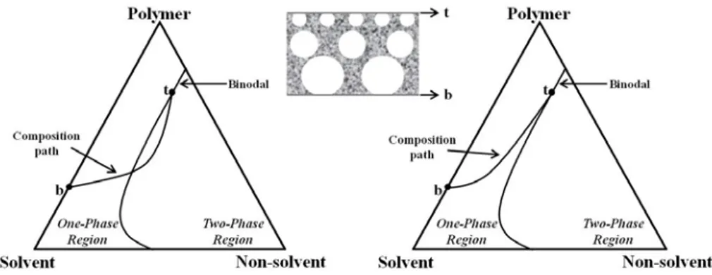
All of the possible combination of three components - polymer, solvent and non-solvent - can be plotted in a ternary diagram. The corners represent the each pure component and three axes indicate three possible binary mixtures while a point in the triangle a ternary composition as shown in Figure 1.4 and Figure 1.5. A ternary phase diagram is very useful in the description of the thermodynamic
properties of a polymer/solvent/non-solvent system.
In the immersion precipitation process the cast layer becomes thermodynamically unstable (or metastable) and phase separation occurs. The three main demixing mechanisms are (Liquid-Liquid, L-L) binodal demixing (nucleation and growth), (Liquid-Liquid, L-L) spinodal decomposition and (Solid-Liquid, S-L) gelation (aggregation formation).
a) Binodal demixing (Liquid - Liquid)
In most phase inversion process, liquid-liquid demixing occurs when a system lower its free enthalpy of mixing by separating into two liquid phases [1, 19]. During membrane formation the composition changes from composition A, which represents the initial casting solution composition, to a composition C, which represents the final membrane composition. The position of composition C on polymer/non-solvent axis determines the overall porosity of the membrane. At composition C the two phases are in equilibrium: a polymer-rich phase, which forms the structure of the final membrane, represented by point S, and a polymer-lean phase, which constitutes the membrane pores filled with precipitant, represented by point L. The point B represents the concentration at which the polymer initially precipitates.
The line connecting all compositions with a common tangent plane to the Gibbs free energy of mixing is called the binodal. The binodal curve divides the system into two phases: one-phase region and two-phase region. When the coagulation path crosses the binodal curve, the system starts to separate through nucleation and growth mechanism or spinodal decomposition. The polymer solution phase separates by nucleation and
growth mechanism into polymer-rich phase (S in Figure 1.4) and polymer-lean phase (L in Figure 1.4) [20].
Figure 1.4. Three components phase diagram of isothermal immersion precipitation process [7].
In Figure 1.5, the phase diagram is divided into a homogeneous region (one-phase region) and an area representing a liquid-liquid demixing gap [16]. The liquid-liquid demixing gap is entered when a sufficient amount of non-solvent is added in the solution [21]. Phase inversion within the metastable area between binodal and spinodal (path A and C in Figure 1.5) is different from the inversion inside the unstable area (path B). The mechanism following path A or C is called nucleation and growth process (NG) and that following B is called spinodal decomposition (SD).
Figure 1.5. Different pathways of a binary casting solution into the miscibility gap of a ternary membrane forming system [2, 22].
When the precipitation pathway enters the two-phase region of the phase diagram above the critical point at which the binodal and spinodal lines intersect, precipitation will occur as growth of polymer-rich phase (path A). If very low concentration of polymer solution is used, in which the precipitation pathway enters the two-phase region of the phase diagram below the critical point, precipitation produces polymer gel particles in a continuous liquid phase. The membrane that forms has little mechanical strength (path C). It thus has to be recognized that only path A is convenient to give membranes [1, 7].
For thermodynamic evaluations of a membrane-forming system, the Flory-Huggins theory of polymer solutions [23], which has been extended to a ternary system containing non-solvent/solvent/polymer by Tompa [24], is usually used. Finally, binary interaction parameters of solvent/non-solvent, polymer/solvent and polymer/non-solvent
calculated from the Flory-Huggins relation is used to understand the structure and performance of a membrane prepared by immersion precipitation.
b) Spinodal demixing (Liquid - Liquid)
The mechanism, following the path B in Figure 1.5, is called spinodal decomposition (SD). This occurs whenever the homogeneous polymer solution directly moves to the thermodynamically unstable zone within the spinodal. Again, two different phases are formed, but instead of developing well-defined nuclei, two co-continuous phases will be formed [2, 25].
Spinodal decomposition is often believed to occur when large temperature gradients induce phase separation [26]. When phase separation is predominately induced via mass transfer it has previously been suggested that it cannot occur via spinodal decomposition [26-27].
c) Gelation (Solid - Liquid)
Gelation is a mechanism for fixing the membrane structure during membrane formation, especially for the formation of the top layer. (On the other hand, the porous sublayer is the result of liquid-liquid phase separation by nucleation and growth.)
A typical (S-L) demixing occurring in membrane formation involves crystallization of semi-crystalline polymers in the presence of a liquid phase. This process is referred to as gelation (or aggregation). The factor determining the type of phase separation at any point in the cast film is the local polymer concentration at the moment of precipitation. After
immersion there is a rapid depletion of solvent from the film and a relatively small penetration of non-solvent. This means that the polymer concentration at the film/bath interface increases and that the gel boundary is crossed [28].
2) Kinetic
Kinetics of phase separation can be explained by diffusion rate (exchange rate) between the solvent and non-solvent in polymer solution and coagulation bath [28-29].
Figure 1.6. Schematic composition path of the cast film by the instantaneous demixing (left) and delaying demixing (right). t: the top of the film, b: the bottom of the film [1].
a) Instantaneous and delayed demixing processes
Figure 1.6 shows the composition path of a polymer film immediately immersed in non-solvent bath after casting. After immersion of cast film, diffusion process between solvent and non-solvent starts from the top of the film (point t). In Figure 1.6 (left), the composition path from ‘point t’ already crossed the binodal, indicating that liquid-liquid demixing occur
immediately. It is called the instantaneous demixing.
In contrast, Figure 1.6 (right) indicates that composition path started from point t remains in the one-phase region of the phase diagram. This means that the no demixing starts immediately after immersion and it takes some time before the membrane is formed [18].
Two type of demixing process leads to different types of membrane morphology. When instantaneous demixing occurs, membrane can be formed very thin top layer and/or porous top layer with a sublayer of a lot of macrovoids. On the other hand, the membrane formed by delayed demixing has with very dense and thick top layer [1, 16].
1.5. Influence of various parameters on membrane morphology
Membrane morphology is strongly influenced by the several factors such as the polymer type, composition of polymer solution and casting (or spinning) conditions including evaporation time, relative humidity and temperature of the air. Also, the compositions of coagulant and coagulation temperature are critical factors which can determine the membrane structure. More details on the effects of 1) the choice of solvent and non- solvent and 2) the composition of the polymer solution on membrane morphology will be discussed below.
1) Choice of solvent and non-solvent
In order to prepare membranes by immersion precipitation, not only perfect solubility of polymer in the solvent, but also the complete miscibility of the solvent and the non-solvent are the most important
factors must take into account.
When the mutual affinity (or miscibility) between the solvent and non-solvent is high, rapid non-solvent and non-non-solvent exchange occurs during the phase inversion process. It results in instantaneous demixing and forming the morphology with a thin top layer and a finger-like structure [30].
Conversely if there is low affinity between the solvent and non-solvent, then low miscibility will delay the onset of demixing and finally forming a dense and thick top layer. Ways to delay the onset of demixing includes the addition of solvent and/or additives into the coagulation bath or the introduction of additives to the dope solution. Polymeric, inorganic salts or even non-solvents of the polymer can be used as the additives for this purpose. In addition, an increase of the temperature in the coagulation bath leads to a higher exchange rate and a higher porosity. Also, the tendency to form macrovoids will be higher.
2) Composition of the polymer solution a) Concentration of the polymer
Increasing the initial polymer concentration in the polymer solution, a much higher polymer concentration at the polymer/non-solvent interface is obtained. Non-solvent inward diffusion is thus lowered and demixing delayed. Denser skins with increased thickness, low porosity of sublayer and lower fluxes is obtained. However, a low polymer concentration in the polymer solution causes a typical finger like structure implying that the volume fraction of polymer decreases due to instantaneous liquid-liquid demixing.
b) Pore forming additives
Membrane morphology can be controlled by the addition of pore forming additives like ionic salts (LiCl, ZnCl2) [31-32], organic acid (acetic acid, propionic acid) [33-35] and polymeric additive (poly(vinyl pyrrolidone) (PVP) [29, 31, 36], poly(ethylene glycol) (PEG) [35, 37]. These additives can also be added to control the viscosity of polymer solution and the evaporation rate. As a result, pore size and porosity of membrane will be modulated, as reflected in the solvent flux and the rejection. For example, the addition of ionic salts such as LiCl, ZnCl2 and organic acid such as acetic acid, propionic acid causes macrovoid formation. The PVP affects the porosity increased and the macrovoids formation disappeared as adding to casting solution. It should be noted that the molecular weight of the polymeric additives also useful tool to control pore size of the membranes.
c) Addition of non-solvents
Non-solvents or low solubility solvents can be used to control the membrane porosity. By adding the non-solvents to the polymer solution, the film will become unstable. Hence, phase separation will occur quickly and equally throughout the film, thus formation of macrovoids [30, 38-41]. On the contrary, non-solvent additive could also suppress macrovoids formation and pores become very well interconnected due to fast diffusion of solvents from the casting film into the coagulation bath [42]. The amount of non-solvent additive should be controlled because amount of non-solvent added must be in the homogeneous region such that demixing does not occur and all the components should be
completely miscible with each other.
d) Addition of volatile (non-)solvents
To prepare integrally skinned asymmetric membranes with the dry-wet phase inversion, the evaporation step is decisive factor [43]. Addition of volatile solvent in the polymer solution occur an instantaneous destabilization in the outer most surface of the nascent film, resulting in a defect-free region with locally elevated polymer concentration. Accordingly, lower solvent permeances and higher rejections through membrane produced will be obtained.
Based on the factors reviewed above, it can be concluded that each specific membrane can be prepared by following the below instructions;
For MF and UF membranes, - Low polymer concentration
- High mutual affinity between solvent and non-solvent - Addition of non-solvent into the polymer solution - Addition of the additives in the polymer solution
For NF membranes,
- Relatively higher polymer concentration than MF and UF - Increase of evaporation time with addition of volatile solvent
- Decrease of exchange rate between solvent and non-solvent by reducing mutual affinity
1.6. Membrane characterization
Membrane process can be used in a wide range of separation applications with a specific membrane being required for every application. Thus, depend on the application, membranes may differ significantly in their structure, physical/chemical properties and permeation properties. Therefore, characterization of the membrane is one of the most important steps in membrane research and development.
In order to evaluate the membrane properties, different instrumental analysis methods can be adopted and each technique has unique power to characterize the membrane property. However, they can be divided into following three categories.
1.6.1. Morphological analysis
1) Microscopic techniques
The main advantage of microscopic analysis is that direct visual information of the membrane morphology is obtained. Most commonly used technique is Scanning Electron Microscopy (SEM). SEM is a very convenient and simple method to obtain an image of the membrane structure by radiation of the sample with an electron beam. SEM has a resolution of up 5 nm and provides good information on the structures including pore sizes and pore shape. Back-scattered electrons (BSE) are different image mode of SEM and beam electrons that are reflected from the sample by elastic scattering. Since heavy elements having high atomic number backscatter electrons more strongly than light elements (low atomic number), and thus appear brighter in the image, BSE images
can provide information about the distribution of different elements in the sample. In addition, Transmission Electron Microscopy (TEM) and Atomic Force Microscopy (AFM) are also frequently used to study membrane structure.
2) Pore size distribution or porometry
The pore size and pore size distribution of membrane are determined by bubble-point test, mercury intrusion method, BET (Brunauer-Emmett-Teller) and porometry method. These methods are very useful for porous membranes both polymeric and inorganic. Especially, the porometry method is measured the diameter of a pore at its most constricted part, the largest pore diameter, the mean pore diameter, the pore distribution, and gas permeability in a porous material. The pores in the sample are spontaneously filled with a wetting liquid. Pressure of an inert gas is slowly increased to remove liquid from pores and permits gas flow through the pores. Measured differential pressures and flow rates of inert gas through wet and dry conditions of the sample are used to compute the number of pores with a certain size. The mean pore size is given the point where the 50% ‘dry’ flow curve crosses the ‘wet’ flow curve [3].
3) FT-IR
Fourier Transform Infrared Spectroscopy (FT-IR) is frequently used for surface analysis and detects absorptions in the infrared region (4000-400 cm-1). Especially this technique can be used to determine the functional chemistry of membrane surface. Functional groups in the
sample absorb energy at specific wavelengths, which results in an attenuated signal at the infrared detector. The infrared spectrum is measured interferometrically using a FT-IR spectrometer. The resulting absorption spectrum is a unique fingerprint of a compound [2].
1.6.2. Physicochemical parameters
1) Swelling
Swelling of membrane uses to know membrane porosity and provides significant influence for permeation performances of membrane. The swelling in dense membranes is evidenced by large permeate fluxes, whilst in porous membranes it could cause a low solvent permeation [44]. Because swelling under pressure would indicate the interaction between solvent and membrane thus polymer chain mobility, which usually results in compaction [45].
2) Mechanical strength measurement
The tensile strength of the membrane is the stress needed to break the sample. After measuring the elongation of the sample at each stress level, tensile modulus can confirm through plot of stress-strain. If the slope is steep, the sample has a high tensile modulus, which means it resists deformation and is hard and brittle. If the slope is gentle, then the sample has a low tensile modulus, which means it is easily deformed and is ductile and tough [1].
1.6.3. Performance parameters
and rejection.
1) Water and solvent permeation measurement
The simplest characterization experiment is the determination of the pure solvent flux. The solvent flux (J, l/m2/h or LMH) through the
membrane can be calculated from the correlation between the volumetric permeate (V, l) and membrane area (A, m2) and unit time (t, h).
𝐽= 𝑉
𝐴 × 𝑡 (1.1)
However, compaction phenomena affect the flux declines as increasing pressure.
2) Solute rejection measurements
Molecular weight cut-off (MWCO) is defined as the molecular weight which is 90 % rejected by the membrane. However, it is not absolute definition for the pore size of membrane, since the retention depends on a number of factors e.g. shape and flexibility of the solute, the interaction of solute with the membrane material, polarization phenomena and different test conditions (pressure, temperature, solvent type, concentration and type of solute), etc. [1].
The rejection (R) is calculated by one of the following two equations [46].
𝑅(%) = �1 −𝐶𝑝
𝐶𝑟�× 100
𝑅(%) = �1 −𝐶𝑝
𝐶𝑓�× 100
(1.3)
where Cf, Cp and Cr represent the concentration of solute in feed,
permeate and retentate, respectively [47-48].
1.7. Transport mechanism
The principal property of membranes used in separation applications is their ability to control the permeation rate of different species [7, 41].
Figure. 1.7. Mechanisms for permeation solutes through porous and dense membranes [7].
To describe the permeation mechanism as shown in Figure 1.7, two different models can be used. One is the pore-flow model and the other model is the solution-diffusion model (Figure 1.8). The transport for the
micro- and macro-porous membranes such as ultrafiltration, microfiltration and Knudsen-flow gas separation occurs by pore-flow. On the other hand, the transport through membranes having a dense polymer layer with no visible pores, such as reverse osmosis, pervaporation and polymeric gas separation membrane are explained by the solution-diffusion model.
(a) Pore-flow (b) Solution-diffusion
Figure. 1.8. Pressure-driven permeation of one component solution through a membrane according to the (a) pore-flow and (b) solution-diffusion models.
The driving forces of pressure, temperature, concentration, and electromotive force for movement of a permeant in membrane are expressed as the gradient in its chemical potential. Thus, the flux Ji, of a
component, i, is described by following equation [49]:
where dμi/dx is the gradient in chemical potential of component i and Li is a coefficient of proportionality (not necessarily constant) linking
this chemical potential driving force with flux.
Restricting ourselves to driving forces generated by concentration and pressure gradients, the chemical potential is described as:
where ci is the molar concentration (mol/mol) of component i, γi is the
activity coefficient linking concentration with activity, p is the pressure, and vi is the molar volume of component i.
The pore-flow model assumes that the concentrations of solvent and solute within a membrane are uniform and that the chemical potential gradient across the membrane is expressed only as a pressure gradient (Figure 1.8. (a)). By Combining Equation (1.4) and (1.5) the pore-flow model can be expressed as following equation.
This equation can be integrated across the membrane to give Darcy’s law in which the permeability coefficient (k) contains structural factors, like membrane pore size, surface porosity and tortuosity.
where k is the Darcy’s law coefficient, equal to Lv, and l is the membrane thickness.
𝑑𝜇𝑖 = 𝑅𝑇dln(𝛾𝑖𝑐𝑖) + 𝑣𝑖𝑑𝑝 (1.5)
𝐽𝑖 = −𝐿𝑣𝑑𝑝𝑑𝑥 (1.6)
The pore-flow model, in which permeants are separated by pressure-driven convective flow through tiny pores, has been proposed and developed by Sourirajan and Matsuura [50]. A separation is achieved between different permeants because one of the permeants is excluded (filtered) from some of the pores in the membrane through which other permeants move. Selectivity results from exclusion, based on incompatibility of molecule parameters such size, shape and charge, with the pores in the membrane [51].
The flow of a solvent through porous membranes which are assumed ideal cylindrical pores aligned normal to the membrane surface can be described in terms of a pore flow model [52].
𝐽𝑣 = 𝜀𝑚𝑑𝑝 2∆𝑝
32𝜇𝑙𝑝 (1.8)
This equation can be used to describe the relationship between the solvent flux and applied pressure where Jv is the solvent flux, εm the
membrane porosity, dp the average pore diameter, Δp the transmembrane
pressure, µ the solvent viscosity and lp the average pore length.
Some membranes have a structure of closely packed pores. In such cases the above equation might be modified for closed pores to give the Carmen-Kozeny equation [52]:
𝐽= ε3
K∙η∙𝑆2 ∙(1 − 𝜀)2 ∆𝑝
∆𝑥 (1.9)
porosity, S the surface area per unit volume, Δp the transmembrane pressure, μ the solvent viscosity and Δx the membrane thickness, respectively.
The transport mechanism for gas separation can be described by Knudsen-flow. In porous membranes when gas transport takes place by viscous flow, no separation is achieved because the mean free path of the gas molecules is very small relative to the pore diameter. In the pore with the larger diameter the gas molecules have more interaction with each other than the pore diameter. By decreasing the diameter of the pores in the membrane, the mean free path of the gas molecules may become greater than the pore diameter. In the pore with the smaller diameter the gas molecules have more interactions with the pore wall than with each other. This kind of gas flow is called Knudsen-flow. The flux in Knudsen diffusion can be described by the following relation [3].
𝐽 =𝜋𝑛𝑟𝑅𝑇𝜏∆𝑧2𝐷𝑖𝑘∆𝑝 (1.10)
Here J is the flux through the membrane, n is the number of pores in the membrane, r is the pore radius, Δp is the transmembrane pressure, Δz is the thickness of the membrane, τ is the tortuosity factor, and 𝐷𝑖𝑘is the Knudsen diffusion coefficient.
𝐷𝑖𝑘 = 0.66𝑟�8𝑅𝑇𝜋𝑀 𝑖
Equation 1.11 shows that the Knudsen diffusion coefficient of a gas molecule is inversely proportional to the square root of its molecular weights. In the porous membrane low separation factors of Knudsen flow are generally obtained [53].
The solution-diffusion model was proposed by Lonsdale et al. [54] and has been revisited by Wijmans and Baker [49]. Basically, this model is useful to describe the transport of a gas, vapor or liquid through a dense (non-porous) membrane. The flux of different components through a membrane is assumed to be by sorption and by diffusion (Permeability (P) = Solubility (S) × Diffusivity (D)). According to solution-diffusion theory, transport occurs by following three steps. (a) selective sorption of penetrant from upstream (or feed side) to membrane surface, (b) diffusion through the membrane from upstream to downstream due to the concentration difference, then (c) desorption from membrane to downstream (or permeate side). Solubility is a thermodynamic parameter and a measure of the amount of penetrant sorbed by the membrane under equilibrium conditions. In contrast, the diffusivity is a kinetic parameter which indicates how fast a penetrant is transported through the membrane.
This model assumes that the pressure within a membrane is uniform and that the chemical potential gradient across the membrane is expressed only as a concentration gradient (Figure 1.8. (b)). The flow that occurs down this gradient is again expressed by Equation (1.4), but, because no pressure gradient exists within the membrane, Equation (1.4) can be written, by combining Equations (1.4) and (1.5), as
This has the same form as Fick’s law where the term RTLi/ci can be
replaced by the diffusion coefficient Di. Thus:
and integrating over the thickness of the membrane then gives, 𝐽𝑖 = −𝑅𝑇𝐿𝑐 𝑖 𝑖 𝑑𝑐𝑖 𝑑𝑥 (1.12) 𝐽𝑖 = −𝐷𝑖𝑑𝑐𝑑𝑥𝑖 (1.13) 𝐽𝑖 =𝐷𝑖(𝑐𝑖𝑜(𝑚)𝑙− 𝑐𝑖𝑙(𝑚)) (1.14)
References
1. M. Mulder, Basic principles of membrane technology. 2nd ed. 1996, Dordrecht, The Netherlands: Kluwer Academic Publishers.
2. A.I. Schafer, A.G. Fane, and T.D. Waite, Nanofiltration - Principles and
applications. 2005, Oxford: Elsevier Ltd.
3. H. Strathmann, L. Giorno, and E. Drioli, An introduction to Membrane Science
and Technology. 2006, Roma: Ufficio Pubblicazioni e Informazioni Scientifiche.
4. M. Ulbricht, Advanced functional polymer membranes. Polymer, 2006. 47: p. 2217-2262.
5. J. Wanqin, X. Nanping, and S. Jun, Progress in inorganic nanofiltration
membranes. Chinese Journal of Chemical Engineering, 1998. 6(1): p. 59-67.
6. M. Ulbricht and H. Susanto, Porous Flat Sheet, Hollow Fibre and Capsule
Membranes by Phase Separation of Polymer Solutions, in Membranes for Membrane Reactors. 2011, John Wiley & Sons, Ltd. p. 491-510.
7. R.W. Baker, Membrane Technology and Applications. 2nd ed. 2004, England: John Wiley & Sons Ltd.
8. L.J. Zeman and A.L. Zydney, Microfiltration and ultrafiltration: Principles and
Applications. 1997, New York: Marcel Dekker, INC.
9. S. Loeb and S. Sourirajan, Sea Water Demineralization by Means of an Osmotic
Membrane, in Saline Water Conversion-II. 1963, American Chemical Society. p.
117-132.
10. K. Scott and R. Hughes, Industrial Membrane Separation Technology, K. Scott and R. Hughes, Editors. 1996, Blackie Academic & Professional: Glasgow. p. 1-7. 11. J.O. Kessler and C.D. Moody, Drinking water from sea water by forward osmosis.
Desalination, 1976. 18(3): p. 297-306.
12. S. Loeb, Production of energy from concentrated brines by pressure-retarded
osmosis : I. Preliminary technical and economic correlations. Journal of
Membrane Science, 1976. 1: p. 49-63.
13. S. Loeb, F.V. Hessen, and D. Shahaf, Production of energy from concentrated
energy costs. Journal of Membrane Science, 1976. 1: p. 249-269.
14. R.W. Baker, Future Directions of Membrane Gas Separation Technology. Industrial & Engineering Chemistry Research, 2002. 41(6): p. 1393-1411.
15. S. Ramaswamy, A.R. Greenberg, and W.B. Krantz, Fabrication of poly (ECTFE)
membranes via thermally induced phase separation. Journal of Membrane Science,
2001. 210: p. 175-180.
16. P. Witte, P.J. Dijkstra, J.W.A. Berg, and J. Feijen, Phase separation processes in
polymer solutions in relation to membrane formation. Journal of Membrane
Science, 1996. 117: p. 1-31.
17. Y.S. Kang, H.J. Kim, and U.Y. Kim, Asymmetric membrane formation via
immersion precipitation method. I. Kinetic effect. Journal of Membrane Science,
1991. 60: p. 219-232.
18. A.J. Reuvers and C.A. Smolders, Formation of membranes by means of immersion
precipitation. Part II. The mechanism of formation of membranes prepared from the system cellulose acetate-acetone-water. Journal of Membrane Science, 1987.
34: p. 67-86.
19. J.H. Kim, B.R. Min, J. Won, H.C. Park, and Y.S. Kang, Phase behavior and
mechanism of membrane formation for polyimide/DMSO/water system. Journal of
Membrane Science, 2001. 187: p. 47-55.
20. H.J. Kim, T. Mohammadi, A. Kumar, and A.E. Fouda, Asymmetric membranes by
a two-stage gelation technique for gas separation: formation and characterization.
Journal of Membrane Science, 1999. 161: p. 229-238.
21. A.F. Ismail, N. Ridzuon, and S.A. Raahman, Latest development on the membrane
formation for gas separation. Journal of Science & Technology, 2002. 24: p.
1025-1043.
22. C. Barth, M.C. Gonçalves, A.T.N. Pires, J. Roeder, and B.A. Wolf, Asymmetric
polysulfone and polyethersulfone membranes: effects of thermodynamic conditions during formation on their performance. Journal of Membrane Science, 2000. 169:
p. 287-299.
23. P.J. Flory, Principles of polymer chemistry. 1953, Ithaca, New York: Cornell University Press.
24. H. Tompa, Polymer solutions. 1956, London: Butterworths.
25. P. Vandezande, L.E.M. Gevers, and I.F.J. Vankelecom, Solvent resistant
nanofiltration: separating on a molecular level. Chemical Society Reviews, 2008.
37: p. 365-405.
26. S.A. McKelvey and W.J. Koros, Phase separation, vitrification, and the
manifestation of macrovoids in polymeric asymmetric membranes. Journal of
Membrane Science, 1996. 112(1): p. 29-39.
27. L.P. Cheng and C.C. Gryte, Limitations on compositional changes during the
isothermal mass transfer process in systems with limited miscibility.
Macromolecules, 1992. 25(12): p. 3293-3294.
28. J.G. Wijmans, J.P.B. Baaiji, and C.A. Smolders, The mechanism of formation of
microporous or skinned membranes produced by immersion precipitation. Journal
of Membrane Science, 1983. 14: p. 263-274.
29. A.F. Ismail and A.R. Hassan, Effect of additive contents on the performances and
structural properties of asymmetric polyethersulfone (PES) nanofiltration membranes. Separation and Purification Technology, 2007. 55: p. 98-109.
30. C.A. Smolders, A.J. Reuvers, R.M. Boom, and I.M. Wienk, Microstructures in
phase-inversion membranes. Part 1: Formation of macrovoids. Journal of
Membrane Science, 1992. 73: p. 259-275.
31. E. Fontananova, J.C. Jansen, A. Cristiano, E. Curcio, and E. Drioli, Effect of
additives in the casting solution on the formation of PVDF membranes.
Desalination, 2006. 192: p. 190-197.
32. E. Yuliwati and A.F. Ismail, Effect of additives concentration on the surface
properties and performance of PVDF ultrafiltration membranes for refinery produced wastewater treatment. Desalination, 2011. 273: p. 226-234.
33. W.-Y. Chuang, T.-H. Young, and W.-Y. Chiu, The effect of acetic acid on the
structure and filtration properties of poly(vinyl alcohol) membranes Journal of
Membrane Science, 2000. 172: p. 241-251.
34. M.-J. Han, Effect of propionic acid in the casting solution on the characteristics of
phase inversion polysulfone membranes Desalination, 1999. 121: p. 31-39.
performance of polysulfone hollow fiber membranes for CO2 absorption. Journal
of Membrane Science, 2010. 348: p. 260-267.
36. S.H. Yoo, J.H. Kim, J.Y. Jho, J. Won, and Y.S. Kang, Influence of the addition of
PVP on the morphology of asymmetric polyimide phase inversion membranes: effect of PVP molecular weight. Journal of Membrane Science, 2004. 236: p.
203-207.
37. J.-H. Kim and K.-H. Lee, Effect of PEG additive on membrane formation by phase
inversion. Journal of Membrane Science, 1998. 138: p. 153-163.
38. J.-Y. Lai, F.-C. Lin, C.-C. Wang, and D.-M. Wang, Effect of nonsolvent additives
on the porosity and morphology of asymmetric TPX membranes. Journal of
Membrane Science, 1996. 118: p. 49-61.
39. S.C. Pesek and W.J. Koros, Aqueous quenched asymmetric polysulfone membranes
prepared by dry/wet phase separation. Journal of Membrane Science, 1993. 81: p.
71-88.
40. J. Ren, Z. Li, and F.-S. Wong, Membrane structure control of BTDA-TDI/MDI
(P84) co-polyimide asymmetric membranes by wet-phase inversion process.
Journal of Membrane Science, 2004. 241: p. 305-314.
41. D. Wang, K. Li, and W.K. Teo, Relationship between mass ratio of
nonsolvent-additive to solvent in membrane casting solution and its coagulation value. Journal
of Membrane Science, 1995. 98: p. 233-240.
42. I.-C. Kim, K.-H. Lee, and T.-M. Tak, Preparation and characterization of
integrally skinned uncharged polyetherimide asymmetric nanofiltration membrane.
Journal of Membrane Science, 2001. 183: p. 235-247.
43. A.F. Ismail and P.Y. Lai, Effects of phase inversion and rheological factors on
formation of defect-free and ultrathin-skinned asymmetric polysulfone membranes for gas separation. Separation and Purification Technology, 2003. 33: p. 127-143.
44. J. Geens, B.V.d. Bruggen, and C. Vandecasteele, Characterisation of the solvent
stability of polymeric nanofiltration membranes by measurement of contact angles and swelling. Chemical Engineering Science, 2004. 59: p. 1161-1164.
45. C. Linder, M. Perry, M. Nemas, and R. Katraro, Solvent stable membranes. 1991. 46. Y.H.S. Toh, X.X. Loh, K. Li, A. Bismarck, and A.G. Livingston, In search of a
standard method for the characterisation of organic solvent nanofiltration membranes. Journal of Membrane Science, 2007. 291: p. 120-125.
47. S.M. Dutczak, M.W.J. Luiten-Olieman, H.J. Zwijnenberg, L.A.M. Bolhuis-Versteeg, L. Winnubst, M.A. Hempenius, N.E. Benes, M. Wessling, and D. Stamatialis, Composite capillary membrane for solvent resistant nanofiltration. Journal of Membrane Science, 2011. 372(1-2): p. 182-190.
48. P. Vandezande, X. Li, L.E.M. Gevers, and I.F.J. Vankelecom, High throughput
study of phase inversion parameters for polyimide-based SRNF membranes.
Journal of Membrane Science, 2009. 330: p. 307-318.
49. J.G. Wijmans and R.W. Baker, The solution-diffusion model: a review. Journal of Membrane Science, 1995. 107: p. 1-21.
50. S. Sourirajan and T. Matsuura, Reverse Osmosis/Ultrafiltration Principles. 1985, Ottawa, Canada: National Research Council of Canada.
51. D.A. Patterson, A. Havill, S. Costello, Y.H. See-Toh, A.G. Livingston, and A. Turner, Membrane characterisation by SEM, TEM and ESEM: The implications of
dry and wetted microstructure on mass transfer through integrally skinned polyimide nanofiltration membranes. Separation and Purification Technology,
2009. 66: p. 90-97.
52. P. Silva, S. Han, and A.G. Livingston, Solvent transport in organic solvent
nanofiltration membranes. Journal of Membrane Science, 2005. 262: p. 49-59.
53. M.T. Ravanchi, T. Kaghazchi, and A. Kargari, Application of membrane
separation processes in petrochemical industry: a review. Desalination, 2009. 235:
p. 199-244.
54. H.K. Lonsdale, Transport properties of cellulose acetate membranes to selected
Chapter 2 Solvent resistant membranes
2.1. Solvent resistant nanofiltration membranes
Nanofiltration (NF) is similar to ultrafiltration (UF) and to reverse osmosis (RO). In all three membrane process, a hydrostatic pressure is applied as a driving force [1]. In addition, the solvent and low molecular weight solutes can permeate the membrane while high molecular weight molecules are retained by the membrane. The main difference between UF and NF is the pore size of the membrane. NF membranes are the same as RO membranes only the network structure is more open [1-2]. Moreover, it should be noted that the NF and eventually also RO membranes carry positive or negative electric charge at the surface. Brief comparison between the processes is summarized in Table 2.1.
The applications of nanofiltration membranes with molecular weight cut-off (MWCO) ranging 200-1000 g/mol have been increased due to the advantages of low energy consumption and no phase change [3]. Especially, since Sourirajan reported the first application of membranes to non-aqueous system in 1964, major oil company and chemical company began to file patents on the use of polymeric membranes to separate molecules from organic solution [4]. Today, the interests of nanofiltration process have been increased in various industrial sectors such as fine chemical, pharmaceutical, food and petrochemical industries [1, 5-7]. The separation of these substances, which is being done by highly energy-consuming evaporation techniques, could be proposed by membrane processes especially with “SRNF membranes” due to
economical, ecological advantages and safety issues [8-9]. In this case solutes including low molecular-weight are rejected, the solvent is removed, and it can be reused in the process.
Table 2.1 Comparative rejection value of RO, loose RO, NF and UF [8].
Species RO Loose RO NF UF Sodium chloride Sodium sulfate Calcium chloride Magnesium sulfate 99% 99% 99% >99% 70-95% 80-95% 80-95% 95-98% 0-70% 99% 0-90% >99% 0% 0% 0% 0% Sulphuric acid Hydrochloric acid 98% 90% 80-90% 70-85% 0-5% 0-5% 0% 0% Fructose Sucrose Humic acid Virus Protein Bacteria >99% >99% >99% 99.99% 99.99% 99.99% >99% >99% >99% 99.99% 99.99% 99.99% 20-99% >99% >99% 99.99% 99.99% 99.99% 0% 0% 30% 99% 99% 99%

![Table 1.1 Advantages and disadvantages of module configuration [2, 8]. Module Chanel spacing (cm) Packing density (m2/m3) Energy costs (pumping) Particulate plugging Ease of cleaning Flat sheet 0.03-0.25 300 moderate moderate good](https://thumb-eu.123doks.com/thumbv2/123dokorg/2875605.9818/22.744.104.645.172.410/advantages-disadvantages-configuration-packing-particulate-cleaning-moderate-moderate.webp)
![Figure 1.4. Three components phase diagram of isothermal immersion precipitation process [7]](https://thumb-eu.123doks.com/thumbv2/123dokorg/2875605.9818/29.744.179.574.227.516/figure-components-phase-diagram-isothermal-immersion-precipitation-process.webp)
![Figure 1.5. Different pathways of a binary casting solution into the miscibility gap of a ternary membrane forming system [2, 22]](https://thumb-eu.123doks.com/thumbv2/123dokorg/2875605.9818/30.744.188.567.134.416/figure-different-pathways-casting-solution-miscibility-ternary-membrane.webp)
![Table 2.1 Comparative rejection value of RO, loose RO, NF and UF [8].](https://thumb-eu.123doks.com/thumbv2/123dokorg/2875605.9818/54.744.97.645.278.836/table-comparative-rejection-value-ro-loose-ro-nf.webp)
![Figure 2.1. General scheme for edible oil processing with possible opportunities to implement SRNF [9]](https://thumb-eu.123doks.com/thumbv2/123dokorg/2875605.9818/64.744.117.620.192.501/figure-general-scheme-edible-processing-possible-opportunities-implement.webp)
![Table 3.1 Chemical and physical properties of solvents used in this study [13-14]. Solvents Formula Molecular weight (g/mol) Density (g/cm3) Viscosity (mPa.s) at 25 oC Ethylene glycol C 2 H 4 (OH) 2 62.10 1.11 13.8 Isopropanol C 3 H 8 O 60.1](https://thumb-eu.123doks.com/thumbv2/123dokorg/2875605.9818/86.744.101.646.565.878/chemical-properties-solvents-molecular-density-viscosity-ethylene-isopropanol.webp)