Scuola di Dottorato in Ingegneria “Leonardo
da Vinci”
Stefano Bennati (Direttore)
Programma di Dottorato in Automatica
Robotica e Bioingegneria
Andrea Caiti (Presidente)
Soft Robotics: Design for Simplicity,
Performance, and Robustness of Robots
for Interaction with Humans
Tesi di dottorato
Tutori:
Prof. Ing. Antonio BICCHI
Prof. Ing. Darwin CALDWELL
Dott. Ing. Nikolaos G. TSAGARAKIS
Dottorando:
This thesis deals with the design possibilities concerning the next generation of advanced Robots. Aim of the work is to study, analyse and realise artificial systems that are essentially simple, performing and robust and can live and coexist with humans. The main design guideline followed in doing so is the Soft Robotics Approach, that implies the design of systems with intrinsic mechanical compliance in their architecture. The first part of the thesis addresses design of new soft robotics actuators, or robotic muscles. At the beginning are provided information about what a robotic muscle is and what is needed to realise it. A possible classification of these systems is analysed and some criteria useful for their comparison are explained. After, a set of functional specifications and parameters is identified and defined, to characterise a specific subset of this kind of actuators, called Variable Stiffness Actuators. The selected parameters converge in a data-sheet that easily defines performance and abilities of the robotic system. A complete strategy for the design and realisation of this kind of system is provided, which takes into account their me-chanical morphology and architecture. As consequence of this, some new actuators are developed, validated and employed in the execution of complex experimental tasks. In particular the actuator VSA-Cube and its add-on, a Variable Damper, are developed as the main com-ponents of a robotics low-cost platform, called VSA-CubeBot, that
the system employed in multi degrees of freedom tasks (bimanual as-sembly and drawing on an uneven surface), are reported.
The second part of the thesis is about the design of multi fingered hands for robots. In this part of the work the Pisa-IIT SoftHand is introduced. It is a novel robot hand prototype designed with the purpose of being as easily usable, robust and simple as an industrial gripper, while exhibiting a level of grasping versatility and an aspect comparable to that of the human hand. In the thesis the main theo-retical tool used to enable such simplification, i.e. the neuroscience– based notion of soft synergies, are briefly reviewed. The approach proposed rests on ideas coming from underactuated hand design. A synthesis method to realize a desired set of soft synergies through the principled design of adaptive underactuated mechanisms, which is called the method of adaptive synergies, is discussed. This ap-proach leads to the design of hands accommodating in principle an arbitrary number of soft synergies, as demonstrated in grasping and manipulation simulations and experiments with a prototype. As a particular instance of application of the method of adaptive syner-gies, the Pisa–IIT SoftHand is then described in detail. The design and implementation of the prototype hand are shown and its effec-tiveness demonstrated through grasping experiments. Finally, control of the Pisa/IIT Hand is considered. Few different control strategies are adopted, including an experimental setup with the use of surface Electromyographic signals.
The author of this thesis would like to thank all the people who ac-companied him, during these years, and who have made possible the realization of many of the ideas that are present in this thesis. With-out the contribution of all these people, withWith-out their passion and their commitment there would have been nothing. Fabio, Felipe, Giorgio, Manolo e Laura for the long days (and nights) of discus-sions and work, for their love and expertise for their also be good friends. Andrea (Dobba) to be always present in the realization of our ideas, for the support and expertise that always shows. All the other guys in the lab, which are many and with which I have always spent happy moments. Prof. Lucia Pallottino for putting up with me over the years, for has been close to me and has tried to make a better student. I want to thank Fabrizio (Fabio) Vivaldi for teaching me what it means to build something, and for having always shown affection and esteem that I was filled with pride. I want to thank Prof. Caldwell and Prof. Tsagarakis for their kindness, expertise and availability. For welcoming me and supported in recent years of new collaborations. I want to especially thank Prof. Bicchi for giving me the opportunity to do what I enjoy, that he always had faith in my work and having enriched it with his ideas.
Abstract v
Acknowledgement vii
Introduction 1
I
Muscles for Robots
15
1 Implementation Principles of VIA 17
1.1 Natural Muscles . . . 18
1.1.1 Mechanics and Control of Vertebrate Muscles . 18 1.1.2 Sarcomere as Building Blocks of the Muscles . . 18
1.1.3 Force in a muscle . . . 19
1.1.4 Muscle spring-like property . . . 21
1.1.5 Muscle sensory receptors . . . 22
1.1.6 Summary . . . 23
1.2 Mechanical translation of a natural muscle . . . 24
1.2.1 VIA as a network of simple components . . . . 27
1.3 Components for robot Muscles - Prime Movers . . . 29
1.3.1 Effort Sources, Flow Sources, Real Sources . . . 29
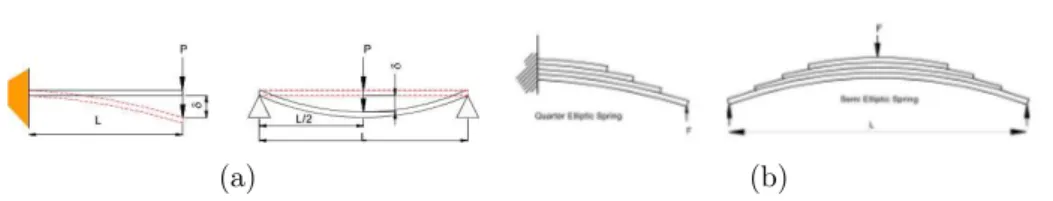
1.4 Components for robot Muscles - Elastic Storage . . . . 47
1.4.1 Materials . . . 49
1.4.2 Elastic Components . . . 56
1.5 Components for robot muscles - Kinetic storage . . . . 73
1.5.1 Inertial Components . . . 74
1.5.2 Velocity Components . . . 78
1.6 Components for robot muscles - Damping systems . . . 90
1.6.1 Damping components . . . 94
2 Variable Impedance Actuator Arrangements 103 2.1 Active compliance . . . 105
2.2 Fix Passive and active/passive compliance . . . 107
2.3 Variable passive compliance . . . 111
2.3.1 Spring preload . . . 112
2.3.2 Physical properties of the spring . . . 123
2.3.3 Mechanically controlled stiffness . . . 129
2.4 Active Damping . . . 133
2.5 Active/Passive Damping . . . 133
2.6 Variable Passive Damping . . . 135
3 Theoretical Comparison of Soft Actuators 137 3.1 Optimal control and VIA - examples . . . 139
3.1.1 Maximization of the output velocity . . . 140
3.1.2 Safety . . . 142
3.2 O. Control and Design G. for Soft Jumping Robots . . 146
3.2.1 Dynamic Models . . . 149 3.2.2 Problem Definition . . . 154 3.2.3 Problem Solution . . . 157 3.2.4 Numerical Solution . . . 157 3.2.5 Analytical Solution . . . 159 3.2.6 Simulation Results . . . 166
4 Functional Specifications of a VSA 173 4.1 Key features of VSA performance . . . 174
4.2 Controlling VSAs . . . 178
4.3 Other characteristics of VSAs . . . 183
4.4 A VSA datasheet . . . 184
4.5 Examples . . . 189
4.5.1 Example 1: a multi-material cutting tool head. . 189
4.5.2 Example 2: a multipurpose tool-head. . . 193
4.6 Guidelines to characterise a VSA . . . 196
4.6.1 Quasi-static load cycles with fixed stiffness preset196 4.6.2 Step Command . . . 201
5 Design VSA to fit task requirements 205 5.1 Components and connections . . . 209
5.1.1 Hypothesis . . . 210
5.1.2 Mathematical Representation . . . 211
5.1.3 Filters . . . 212
5.1.4 Layout . . . 214
5.2 Generic Layout and mathematical model . . . 216
5.3 Classification and performance analysis . . . 220
5.4 Mechanical design of a selected layout . . . 227
5.4.1 Mechanical layout implementation . . . 227
5.4.2 Variable Stiffness mechanism implementation . 229 5.5 Mathematical model of the implementation . . . 231
5.5.1 Non-linear Spring . . . 231
5.5.2 Equilibria . . . 233
5.6 Experimental Results . . . 236
5.6.1 Experimental Setup . . . 236
5.6.2 Torque-Stiffness characteristic . . . 237
5.6.3 Stiffness Settling Time and Stiffness Velocity . . 240
5.6.4 VSA-HD datasheet . . . 241
6 VSA -CUBE: design of a VS Servo Actuator 245 6.1 The VSA-CUBE . . . 247
6.2 Mechanical design . . . 250
6.4 Mathematical Model . . . 253
6.5 The CUBE-BOT a multiple degrees of freedom platform256 6.6 Experiments . . . 257
7 Design a Variable Impedance Actuator 265 7.1 Variable Impedance Actuator layouts . . . 266
7.2 Variable Damper Design . . . 269
7.2.1 Requirements . . . 269
7.2.2 Mechanical Design . . . 272
7.3 Variable Damping Experimental Tests . . . 278
7.4 Variable Impedance Experimental Tests . . . 279
8 VIA@work:Drawing on a wavy surface 285 8.1 Problem statement . . . 287
8.2 Optimal workspace stiffness . . . 289
8.3 Optimal joint stiffness . . . 294
8.4 Experimental Tests . . . 295
9 VIA@work:towards variable impedance assembly 303 9.1 Problem Definition . . . 307
9.1.1 Kinematics . . . 307
9.1.2 Dynamics . . . 308
9.1.3 The task . . . 308
9.2 Problem Solution . . . 309
9.2.1 From parallel to serial manipulation . . . 309
9.2.2 Search Algorithm . . . 310
9.2.3 Insertion . . . 311
9.2.4 Control . . . 314
9.3 Simulation and Experimental Results . . . 316
II
Hands
323
10 Anatomy of the human hand 325 10.1 Structure of the human hand . . . 32610.2 Main degrees of freedom of the hand . . . 333
10.3 Main motor functions of the hand . . . 336
10.3.1 Grasp classification . . . 340
10.4 Synergies in human hands . . . 341
11 Robotic hands 343 11.1 Joints in robotic hands . . . 344
11.1.1 One degree of freedom joints . . . 345
11.1.2 Two degrees of freedom joints . . . 355
11.1.3 Three degrees of freedom joints . . . 358
11.2 The palm . . . 358
12 Pisa/IIT SoftHand:Design and Control 361 12.1 Hand Actuation, Synergies and Adaptation . . . 364
12.1.1 Fully Actuated Hands . . . 364
12.1.2 Approaches to Simplification . . . 369
12.1.3 Soft Synergies . . . 371
12.1.4 Underactuated Hands . . . 377
12.1.5 From Soft to Adaptive Synergies . . . 379
12.2 A Modular Hand with Four Adaptive Synergies . . . . 383
12.3 The Pisa/IIT SoftHand . . . 386
12.4 Experimental . . . 391
12.4.1 Force and torque measurements . . . 393
12.4.2 Grasp Experiments . . . 393
13 Pisa/IIT SoftHand:control through sEMG signals 405 13.1 Overall study design . . . 407
13.2 Testing . . . 408 13.3 sEMG . . . 408 13.4 Control Architecture . . . 409 13.5 Questionnaire . . . 410 13.6 Data Analysis . . . 412 13.7 RESULTS . . . 413
14 Pisa/IIT SoftHand:teleimpedance control 417
14.1 SoftHand Synergy References . . . 418
14.2 Interaction Torque Observer . . . 421
14.2.1 Hand Disturbance Model Identification . . . 423
14.3 Controller Design . . . 424
14.4 Experimental Setup . . . 425
14.5 Results . . . 427
14.5.1 Interaction Torque Observer . . . 427
14.5.2 Grasping Experiments . . . 427 A Joints summary sheets of robotic hands 433
This thesis studies novel design possibilities of the next generation of advanced Robots, capable to fill the gap with one of the most advanced mechanical system that lives in our natural environment: the Human. The main goal of the work is the realisation of essentially simple, performing and robust artificial systems, taking in to account one basic rule: these systems should live and coexist with humans in a world designed for humans. Behind these statements there is the, obvious awareness that this fatigue can not be solved in one simple thesis, but there is also the hope that this thesis could be a small advance, yet tangible, in the growth of Robots of the near future.
One of the main guidelines of this thesis, can be clearly explained looking at the incommensurate differences that exist between a Hu-man and a Robot in the near state of art. These differences lie not only in the brain and cognitive capabilities, that for sure represents one of the most exciting challenges of robotic research, but also in the intrin-sic mechanical performance of these systems, and in the capabilities that a natural system can show, such as running, jumping, manipu-lating, and interacting with the surrounding world, fighting etcetera. Fig. 1 shows a sequence where many of the mechanical possibilities of a human system are emphasised: explosive movements, robustness, adaptiveness, force, agility, velocity, etcetera. Fig. 2 is the state of art robotic counterpart, in particular this sequence shows of one of the
Figure 1: The sequence shows a parkour perform a series of jumps and articulated movements exploiting some intrinsic characteristics of the human body, such as power, robustness, explosive energy, precision etcetera [W31]
most advanced robots in the world executing a task which difficulty is very high for a robot but is incomparably low when confronted with Fig. 1. The sequence of Fig. 2, shows not only the limitation of a tra-ditional robotics architecture, but also the intrinsic fragility of these systems. Fig. 4 shows a sequence of what a Robot approaching the Human performance should do: unfortunately this sequence is just a computer graphic animation: these three pictures together illustrate the driving push behind a relevant part of the research community.
A concrete example of what this means is the new DARPA Robotics Challenge [W34,W35]. This competition focuses on humanoid robotics
robotic system. This old video shows some limitations of conventional robot designs [W33].
and its primary goal is:
[...] to develop ground robotic capabilities to execute complex tasks in dangerous, degraded, human-engineered environments. The pro-gram will focus on robots that can use available human tools, ranging from hand tools to vehicles. The program aims to advance the key robotic technologies of supervised autonomy, mounted mobility, dis-mounted mobility, dexterity, strength, and platform endurance. Super-vised autonomy will be developed to allow robot control by non-expert operators, to lower operator workload, and to allow effective operation despite low fidelity (low bandwidth, high latency, unreliable) commu-nications. [W35]
Motivations behind these ambitious goals are related to the possi-bility of use robots in situation where humans are unable to get close enough to complete their mission, such for example after a nuclear
disaster or an earthquake disaster. In this situation a robot could be helpful, but a robot that can deal with this kind of situation has to come. In fact:
[...] Our best robotic tools are helping, but they are not yet robust enough to function in all environments and perform the basic tasks needed to mitigate a crisis situation. Even in degraded post-disaster situations, the environment is scaled to the human world, requiring navigation of human obstacles such as doors and stairs, manipulation of human objects such as vehicles and power tools, and recognition of common human objects such as levers and valves [W35].
And is for these reasons that the aim of the competition is:
[...] meet these needs by developing robotic technology for disaster response operations. This technology will improve the performance of robots that operate in the rough terrain and austere conditions char-acteristic of disasters, and use vehicles and tools commonly available in populated areas. [W35].
Fig. 3 shows some tasks that the robot has to deal with during the competition, such as: operate a valve or use a jackhammer [W35]. Other tasks include walking over rough terrain, walking on an unsta-ble bridge, use of tools (drills, screwdriver, etc.), drive a car, open or close doors, etcetera. As said before, the source of all differences can not be demanded only to limitations in the cognitive and brain capabilities of the robotics system, but have to be sought also in the intrinsic peculiarities of the Human body, and talking about the Hu-man body, we have to take in to account the full body. Fig. 5 shows a frame of the sequence of Fig. 1, in this specific moment all
robots participating the competition have to solve: operate a valve and use a jackhammer.
Figure 4: The sequence shows some frames extracted from a famous tv spot where a robot shows performance near to the human being [W36]. the components of the human body have an active role in the exe-cution of the task; hands, wrists, arms, legs, spine and foots are in-volved together in the action, the full architecture (bones, ligaments, muscles, sensors, etcetera) gives to the human system the ability to perform this impressive movement, enpowering the human with the properties we have highlighted before (robustness, power, etcetera).
Figure 5: The picture shows a frame of the sequence reported in Fig. 1, the image highlights an instant where the full body is involved in the performance. Arm, hands, spine, feets, all the mechanical body parts have a role in the movements, exalting some mechanical characteristics such as adaptability, power, force etcetera.
Taking into account Fig. 5, it is a useful exercise highlight some of the main properties of the human body and translate them in a list of mechanical design parameters. These parameters are summarised in Tab. 1. This exercise is useful to highlight how some of these specifications lack in a robotic system, as reported in Tab. 2. An-other useful consideration has to be made on the simplicity of the Human system. With a reasonable grade of abstraction it is possible to consider the human body as a combination of simple and redundant
Reliable Fatigue life Long time task Continuous power Explosive task Peak power Safe in interaction Safety Normatives Low energy consumption Efficiency
Accurate Repeatibility, Precision Adaptable Designed for Uncertain
Table 1: Main mechanical properties of the musculoskeletal system. Human Feature Robotic System
Robust no impacts are allowed Reliable under some load conditions Powerful Mass/power ratio is not comparable Explosive Energy Mass/power ratio is not comparable Safe in interaction no interactions are allowed
Efficient not in autonomy Accurate repeatibility, precision Adaptable Designed for specific tasks
Table 2: Main mechanical properties of conventional robotic systems elements; from a mechanical point of view an organised combination of: structural frame (bones), elastic joints (ligaments) and actuation system (muscles). This feature is a peculiar property that must be taken into account in the design of a robotic body system. Moving from these abstractions and translating them in a real mechanical system is not an easy work, and is a process that can follow different theories and approaches. This thesis bases its work on some simple rules: understanding and interpreting the Human body architecture and its control policies and translating them in a proper mechanical and control platform, not passively coping the human system. The main design guidelines followed in this work is characterised by the adoption of the Soft Robotics Approach. A reasonable definition of
the meaning of these three words could be: a set of design techniques and control strategies, based on the realisation of inherently elastic mechanical systems, prompted as one of the possible interpretation of the human system. Translated in a much more compact way it means: to add mechanical compliance in the robot architecture. The ultimate correctness of this approach is not questioned within the limits of this thesis, but many factors exist that encourage the entire research community in the prosecution of this approach, motivations coming from biophysics, analysis of mathematical models and prac-tice and experimental evaluation. Fig.s 6(h), 7, 8 and 9 show some of the most recent advancements in Robotics development. All these images show robots based and developed following the ideas behind the Soft Robotics, as for example the introduction of passive elastic elements in the architecture of the robots (Fig.s 7, 8 and 9), or ac-tively controlling the impedance of the system (Fig. 6) or exploiting the intrinsic elasticity of the mechanical components Fig. 6.
Figure 6: The sequence shows the new ASIMO [W32] running, with a velocity of [9km/h], and jumping [W37]. In this case each joint is controlled with an active impedance controller, an intrinsic elasticity is provided from the Harmonic Drive gearboxes [W38].
Main Research Arguments Fig. 10 shows the main research ar-guments of this thesis: robotic muscles and hands. This kinds of dis-tinction is made in order to distinguish and isolate two macroscopic
at Italian Institute of Technologies (IIT) [W40]. Each joint has a pas-sive elastic element in series with the output shaft of the actuator. A sophisticated impedance control is employed to have these kinds of performance.
Figure 8: The sequence shows the robot PET-MAN (Boston Dynam-ics [W41]) performing some advanced tasks such as: climb an obstacle or walk in uneven terrain [W42]. The robot have a pneumatic actua-tion system, for this reason has an intrinsic passive compliance. subsystem of the Human Body. These two systems have many com-mon elements but in general require different design approaches, and different solutions; also according to different roles and different scale they have in the human system. For both arguments my research activity focused on the mechanical design and in the implementation of solutions for the joints and the actuation systems.
Figure 9: The sequence [W43] highlights the intrinsic robustness of the new DLR Hand-Arm system [W44]. In this device each joint is equipped with a Variable Stiffness Actuator, also the hand has a struc-ture where each joint has a passive compliance system of actuation. Main Contributions and their correlation with international research projects The main contributions of my Thesis can are summarised in:
• A contribution is given on the classification and analysis of newest soft robotics systems, the effort focuses on the most re-cents advances in the development of Variable Impedance Actu-ators (Chapter 2). It is a result produced inside the European Community’s projects VIACTORS [P52] and SAPHARI [P53]. • Introduction of a possible standard data-sheet for a specific ty-pology of robotic muscles, variable stiffness actuators. It is a for-malisation where the main functional parameters and the main characteristics are summarised and arranged in an organised and practical way, taking in to account, as first objective, the user’s point of view (Chapter 4). The work done in this part
of the thesis is a result produced inside the European Commu-nity’s projects VIACTORS [P52] and SAPHARI [P53], with the collaboration of all its partners.
• Formalisation of a new mechanical design strategy for the de-velopment of robotic muscles, this new procedure takes into ac-count their intrinsic mechanical structure (Chapter 5). It is a result produced inside the European Community’s projects VI-ACTORS [P52] and SAPHARI [P53].
• Introduction of a new, high-end, variable stiffness actuators (Chapter 5). This new system is a result of the design guide-lines described in the first part of the same chapter. It is a result produced inside the European Community’s projects VI-ACTORS [P52] and SAPHARI [P53].
• Introduction of a new affordable and simple variable stiffness actuator, VSA-Cube. The actuator is developed to be the ba-sic component of a robotic platform, VSA-CubeBot, developed for a diffusion of variable stiffness technology. The concept of
variable stiffness servo actuator is introduced (Chapter 6). The VSA-CubeBot represents, also, one of the first multi degrees of freedom platform equipped with Variable Stiffness Actuators. It is a result produced inside the European Community’s projects VIACTORS [P52] and SAPHARI [P53].
• Introduction of one of the first variable impedance actuator. This is a system where both stiffness and damping can be changed simultaneously and independently (Chapter 7). It is a result produced inside the European Community’s project SAPHARI [P53].
• Formalisation and implementation of experiments multi degrees of freedom with a robotic platform, VSA-CubeBot, totally equipped with variable stiffness actuators (Chapters 9 and 8). It is a re-sult produced inside the European Community’s projects VI-ACTORS [P52] and SAPHARI [P53].
• Introduction of new design strategies for the development of a new generations of robotic hands, based on the introduction of the concept of the soft synergy framework inside the mechanical architecture of the hand. To do this kind of work a new frame-work, called adaptive synergies, is introduced and implemented in the Pisa/IIT SoftHand (Chapter 12). It is a result pro-duced inside the European Community’s projects THE [P54], Roblog [P55] and SoftHands [P56].
• Introduction of a new soft, robust and simple robotic joints, thinked as an evolution of the well known HillBerry joint. The most important novelty in the new design is the introduction of elastic ligaments between the moving parts (Chapter 12). It is a result produced inside the European Community’s projects THE [P54], Roblog [P55] and SoftHands [P56].
• Contribution in the realisation of a new control strategy for synergistic under-actuated robotic hands based on the adoption
THE [P54], Roblog [P55] and SoftHands [P56].
Structure of the thesis The thesis is organised as follow: Part One is about design of Robot Muscles, starting from simple consider-ations on human muscles and their translation in a mechanical model, some elements are reported about the basic components constituting the new generation of robotic actuator and a short panoramic on the state of the art is provided (chapter 1 and 2). Chapter 3 is a short dissertation on optimality principle in design and control of these new generations of actuators, in particular some elements are highlighted in order to justify some design strategies selected for the develop-ment of the robotic muscles. An example of optimal control design for the realisation of a soft jumping robots is analysed in detail (Sec. 3.2). Chapter 4 is an explanation of the main mechanical and con-trol parameters constituting a robotics muscle, with particular atten-tion to one possible standardisaatten-tion of the funcatten-tional specificaatten-tions. Starting from notions of Chapter 4 in Chapter 5 some new design guidelines and methodologies are highlighted for the realisation of a robot muscle, these elements culminate in the design of a new variable stiffness actuator, called VSA-HD. Chapters 6 and 7 deal the design of a small, economic and affordable robotic platform, useful for the diffusion and test of soft robotics muscles. This approach culminate in the realisation of one of the first variable impedance actuator for robots. Chapter 9 and 8 show some experimental results obtained with the platform developed in Chapter 6 and 7. For both examples mathematical and experimental results are provided.
Part Two deals with the problem of the hands design. After a short dissertation on the human hand architecture and its functional role in the human system (chapter 10), with some notes on its con-trol strategy and policies, a short discussion on robotics hands and their architecture is made, highlighting, in particular, their mechan-ics characteristmechan-ics (chapter 11. Chapter 12 is about the design of the
Pisa/IIT Soft Hand, with particular attention on the actuation sys-tem, joints design, and feasible implementation. Chapter 13 and 14 show the Pisa/IIT Soft Hand hardware employed with different con-trol methodologies, including concon-trol with sEMG signals and with a tele-impedance control strategy.
Clarification This thesis collects and presents many of the articles (published, in press or under submission) of the author, arranging them accordingly with the train of thought that has characterised his Ph.D.. The development of complex systems is not possible un-less accompanied by a working group be able to cover all aspects of development, from the mathematical synthesis up to the practical im-plementation. Is of particular importance in the eyes of the author, point out how his work, carried out in this thesis, above all concerns the ideation, design and implementation of the various mechanical systems presented. The author definitely wants to emphasise that his work without the work (on electronics, control, mathematics) and ideas of the whole group of colleagues and supervisors would not have been possible otherwise.
Chapter
1
Implementation Principles of
Variable Impedance Actuation
The text of this chapter is adapted from:
[P52] European Community’s projects VIACTORS. Deliverable D1.1 [A1] B. Vanderborght, A. Albu-Schaeffer, A. Bicchi, E. Burdet, D. Caldwell, R. Carloni, M. Catalano,O. Eiberger, W. Friedl, G. Ganesh, M. Garabini, M. Grebenstein, G. Grioli, S. Haddadin,H. Hoppner, A. Jafari, M. Laffranchi, D. Lefeber, F. Petit, S. Stramigioli, N. Tsagarakis, M. Van Damme, R. Van Ham, L.C. Visser, S. Wolf, Re-view of Variable Impedance Actuators, under submission to Robotics and Autonomous Systems [A2] Vanderborght B., Albu-Schaeffer A, Bicchi A, Burdet E, Caldwell DG, Carloni R, Catalano MG, Ganesh G, Garabini M, Grioli G. Variable Impedance Actuators: Moving the Robots of Tomorrow. International Conference of Intelligent Robots and Systems - IROS 2012- Best Jubilee Video Award. 2012.
The goal of this chapter is to extensively consider the different princi-ples and technologies by which a variable impedance actuator system can be realized. We begin with a brief description of the characteris-tics of natural muscles.
1.1
Natural Muscles
1.1.1
Mechanics and Control of Vertebrate
Mus-cles
The major consequence of the information processing that takes place in the vertebrate brain is the contraction of skeletal muscles, which move the bones and flesh. This section1 examines the mechanical
properties and control of these muscles which are responsible for vol-untary motor control.
1.1.2
Sarcomere as Building Blocks of the Muscles
A typical muscle consists of many thousands of muscle fibers working in parallel. It is often useful to consider motor units, i.e. one or several fibers with the motor neuron activating them. A single muscle fiber contains several myofibrils, made of sarcomere separated by Z disks, which can be examined under the microscope.
In a sarcomere, thin (actin) and thick (myosin) filaments are ar-ranged in a hexagonal lattice, such that one thick filament interacts with six thin filaments. Cross-bridges linking actin and myosin pull towards center resulting in muscle shortening. Huxley’s model states that actin and myosin filaments slide against each other by repeated attachment and detachment of cross-bridges. If muscle shortening is prevented, isometric tension develops.
At a given (constant) muscle activation, the active force in a sar-comere declines at long lengths as filament overlap is reduced, as there are fewer actin sites available for myosin binding. Active force also declines at short lengths because filaments interfere. Further, sarcom-ere force and stiffness vary with muscle length in proportion to the number of cross bridges. In addition to this active force, the passive
1
The text of this section is adapted from the lecture notes of E. Burdet for his neuromuscular control course at Imperial College London.
force increases at long lengths as structural proteins and myofilaments are stretched.
Sarcomere force also depends on velocity. It increases by 20-50% by lengthening. Detaching and reattaching causes the myosin heads to spend more time near the end of their power stroke by shortening, resulting in decreasing ability to generate force.
Figure 1.1: Experimental setup to measure how muscle tension depends on length and velocity and fit of the resulting data, which were obtained from the soleus muscle of a cat during tetanic activation [57].
1.1.3
Force in a muscle
We may expect that muscles have similar mechanical properties as sarcomeres, as they are composed of them. By controlling the muscle length at constant activation and measuring its tension (Fig. 1.1 top panel), one can estimate how the force developed by a muscle depends on its length and contraction/extension velocity.
The bottom panel of Fig. 1.1 shows that muscle force at constant activation depends both on muscle length and velocity in a nearly independent way, with similar length and velocity dependencies as in a sarcomere. Note that small changes in velocity around zero create particularly large changes of force.
Human motor control can make use of the mechanical proper-ties of muscles. For example, the (biarticular) hamstring muscles are
used in the swing phase of walking. The knee is flexed thus tends to shorten the hamstrings, while the hip is also flexed, and thus tend-ing to lengthen them. Therefore, the hamstrtend-ings are not shortened and can produce a large force (Fig. 1.1). Using monoarticular knee muscles to flex the knee would consume much energy to produce the necessary force, while shortening the hip extension through the ham-strings also helps decelerating the leg by elasticity.
Figure 1.2: Lowpass filtering property of muscles (see [58]).
In order to investigate how fast muscles respond to a motor com-mand, [58] studied the response of periodical action potentials while varying the frequency. We see in Fig. 1.2 that the tension varies with the same periodicity as the action potential. However, the amplitude of the muscle force modulation decreases as the action potential fir-ing rate and phase-lag increase. This shows that muscles act like a low-pass filter.
The bottom panel of Fig. 1.2 analyzes how the amplitude de-creases with the frequency of the action potential, corresponding to the gain plot. We see that muscles filter the stimuli with a cutoff frequency around 1-2Hz for action potential frequency modulation. This does not mean that you will not be able to make movements at higher frequency. For example you can oscillate with one finger or the wrist until 4-5 Hz, but the amplitude of the oscillations will decrease with increasing amplitude (as you can try).
Figure 1.3: The tension in isolated cat medial gatrocnemius (MG) and soleus (SOL) muscles in the same hindlimb is measured while muscle is gradually stretched and shortened [59].
1.1.4
Muscle spring-like property
We know from everyday experience that muscles are “elastic”. In a perfect spring, force increases linearly with elongation according to Hooke’s law, and when released decreases of the same amount. When a muscle is gradually lengthened (Fig. 1.3), its tension increases monotonically, first linearly and then with smaller slope. When it is then shortened, tension decreases monotonically, but on a curve below the tension measured during lengthening.
This hysteresis means that there is an energy loss when muscles are lengthened and then shortened. Energy is the integral of length multiplied by tension, so the energy loss corresponds to the surface between the upper and lower curves. The large energy loss means that muscles not only develop elastic forces, but also dissipate energy.
figure
How does elasticity of a muscle depend on the force applied on it? This cannot be measured as the gradient of the force length relation-ship in Fig. 1.1, as these figures show the tension in the static state when the force from the spring-like properties of the muscle are not contributing to the measured force. However we can already obtain a
Figure 1.4: (Intrinsic) stiffness K and damping B in a deafferented cat muscle [60] in response to a random perturbation of a given amplitude in a given frequency range.
rough idea by examining the derivative of the length-tension curve in Fig. 1.3. To examine this systematically, [60] applied a random po-sition perturbation with controlled frequency range on a deafferented cat muscle. Stiffness and damping were identified from the measured force in response to the random perturbation.
Fig. 1.4 shows that muscle stiffness increases linearly with mus-cle force. Stiffness tends to increase at higher frequencies, and de-creases with larger perturbation amplitude. Damping also inde-creases with muscle force and decreases at higher frequencies, i.e. with higher velocity (Fig. 1.4).
1.1.5
Muscle sensory receptors
Sensory receptors transform energy into changes in membrane poten-tial. Photoreceptors transform light, nociceptors and mechanorecep-tors mechanical energy, thermorecepmechanorecep-tors thermal energy, chemorecep-tors and nocicepchemorecep-tors chemical energy. Sensing equipping the human body can be classified in two types:
• exteroception detects external stimuli, including vision, hearing, smell, taste, touch, temperature, pain, via sensory receptors in the eyes, ears, nose, tongue, and skin;
• proprioception detects output of the motor system. It senses limb position and movement via mechanoreceptors in muscle, joints and skin
Skeletal muscles are richly supplied with a variety of propriocep-tors. Muscle spindles and Golgi tendon organs are particularly im-portant for motor control. Muscles spindles are placed in parallel to the muscle fibers and Golgi organs in series to a muscle. Correspond-ingly, spindles measure changes of length while Golgi organs measure forces.
Golgi tendon organs are encapsulated structures about 1mm in length, which are located at the junction of muscle and tendon. Af-ferent axons intertwine among collagen fascicles, such that stretching of the ending organ straightens the collagen fibers, which deforms nerve endings, causing them to fire.
1.1.6
Summary
Muscle have the following mechanical properties:
• muscle tension increases with stretch and activation;
• tension at fixed activation depends on both length and velocity; • muscles act like a low-pass filter with a cutoff frequency around
1-2Hz for action potential frequency modulation; • muscle have spring-like properties;
• stiffness and damping increase with activation.
Muscles are equipped with sensors which can provide stretch (e.g. spindles) and force (e.g. Golgi tendon organs) information to the nervous system.
1.2
Mechanical translation of a natural
mus-cle
In this section is introduced a simple model with which is possible translate the functional characteristics of a natural muscle in a me-chanical systems. Although it is a rough simplification, it is useful to understand, design and control artificial muscles. From Sec. 1.1 it is clear how a natural muscle can change its own stiffness and damping, this means that it can change its impedance. In this section a simple definition of what is the mechanical impedance is provided.
The simplest example of mechanical impedance is a spring, i.e. a sample of material which exhibits a proportional relation between applied force f and displacement at equilibrium y given by
y = cf.
The proportionality constant c is the spring compliance. The inverse of this relation, i.e.
f = ky
introduces the spring stiffness as the reciprocal of compliance, k = c−1
.
The concepts of compliance and stiffness are generalized from static (equilibrium) to dynamic cases by introducing the notion of admittance and impedance, respectively.
Consider e.g. a damper made of viscous material that opposes to displacements proportionally to how quick they are, i.e.
f = b ˙y,
where b is the damping coefficient. Finally consider the inertial effects of accelerating an equivalent mass m of material under deformation,
In most materials the three effects occur at the same time, and we have that the force/displacement relation is described by an ordinary differential equation. In our simple example we have
f = m¨y + b ˙y + ky, (1.1) i.e. a relation between two functions of time, f(t) and y(t). Such a dif-ferential equation describes a dynamical system. This can be regarded as a causal system if displacement (appearing with the highest-order derivative) is regarded as the effect (or output), and force as the cause (or input). Indeed, knowledge of initial conditions on displacement, and the time course of force, determine all subsequent evolution of displacement.
The differential equation (1.1) is linear and time-invariant. To analyze its input-output behavior, it is useful to introduce Laplace transforms from functions in the domain of time t to functions in the domain of the complex variable s. By denoting F (s), Y (s) the transforms of f(t) and y(t), respectively, one has immediately
F (s) = (ms2+ bs + k)Y (s). (1.2) The operator Z(s) := (ms2+ bs + k)is called (mechanical) impedance
of the spring-damper-mass system, and is clearly a generalization of the stiffness coefficient k to a dynamic setting2. The reciprocal
op-erator of impedance, called admittance A(s), generalises compliance, and maps forces in displacements as
Y (s) = 1
ms2+ bs + kF (s) := A(s)F (s). (1.3)
You want to point out that the above considerations can be extended to systems with several degrees of freedom, however, for the purposes of this thesis such an extension is not required.
2
It should be noted that in the literature, the term impedance is sometimes used to denote the relationship between velocity and force. This is more consistent with the definition of electrical impedance in terms of flow and effort correspondence. However, the usage of this chapter is more convenient to our purposes.
Taking into account what said before, and what shown in Sec. 1.1 a robotic muscle can be schematised as in Fig. 1.5(a), where k, c and m are respectively the stiffness, the damping factor and the output inertia of the robotic muscles; f represent the source force in the system and y the output position.
Due the capability of the muscle to change its intrinsic properties (as said stiffness, damping and inertia) a much more real schematisa-tion is given in Fig. 1.5(b), where arrows indicates the capability of the robotic muscle to vary, independently, its stiffness, its damping and its inertia, in other words is capable to change its impedance. A
(a) (b)
Figure 1.5: Mechanical model of a robotic muscle, with a fixed impedance (a). Mechanical model of a robotic muscle, with variable impedance capabilities (b).
robotic muscle capable to change one, two or all together these pa-rameters is called Variable Impedance Actuator (VIA). Many times only one of these parameters can be modified, in this case, these sys-tem are called Variable Stiffness Actuators, Variable Damper Actua-tor or Variable Inertia Trasmission, in function of which parts of the impedance can be changed. Other common ways to call this type of systems are: Variable Passive impedance actuator (or Joint), Variable Passive compliance Actuator (or Joint) and Variable passive Damp-ing Actuator (or joint). In this case the word passive, means that the impedance (or the single components k, c and m) can be changed due the mechanical intrinsic structure of the system (see Sec. 2.3). This name is used to differentiate these system from system where the impedance (or the single components k, c and m) is changed by an
ac-tive control strategy (see Sec. 2.1). There is also a category between this two families that is called Variable Active/Passive Impedance Ac-tuator (or Joint), in this case the systems can vary the own impedance by an active control, but have in their mechanical design some passive elements, such as springs (see Sec. 2.2). The author wishes to point out that this nomenclature is not uniquely used in the scientific com-munity, however, seems to be that, over the years, it is increasingly asserted. In this thesis, we will typically refer to this nomenclature, in some specific cases will be introduced to the various variants.
1.2.1
VIA as a network of simple components
A widely known approach for the modelization of complex dynamical systems, consists in breaking them down into a network of simpler elements, whose behaviour is already known and easily described.
The resulting network of simple components can then be anal-ized with consolidate mathematical tools (i.e.: Northon and Thevenin Theorems, Kirchoff Laws, and network theory in general). Results of this analysis can used to infer the behavior of the real system, be it mechanical, hydraulic, pneumatic, electric, magnetic, etcetera.
An important characteristic of these networks is the possibility to highlight the energy exchanges in the model, analysing the whole in terms of flow/effort variable pairs. In short, a flow/effort pair is a set of two variables on which a product function is defined. The result of this product is a power, representing the energy flowing between those components of the system that share that particular flow/effort pair.
The particular name choosen for these two variables reflects an intrinsic isomorphism that can be found among many different fields of physics. Flow variables are associated with quantities that are related to movement or transportation: linear or angular velocity, heat flow, volume flow or mass flow, etc. Effort variables, on the converse, identify tensions and potentials: force, torque, temperature, pressure, etc..
One straightforward consequence of this modelization approach, and an important aid in the analisys of systems is the possibility to categorize the simple elements constituting a network, in function of their energetic behaviour.
A first consideration is that, neglecting mass/energy transforma-tions, which is always the case in most engineering applicatransforma-tions, en-ergy is always conserved, and can only move with respect to what is considered as our system. More in particular, it can stay in the same energetic domain, like when a mass and a spring exchange power os-cillating, or transfer from one to another, like when an electric motor transforms electromagnetic energy into movement.
This first consideration allows for a first categoryzation: on one side there are Storage elements, that keep the energy inside the same energetic domain, while on the other there are Transducers, that allow a flow of energy from one domain to another. This includes elements that inject energy inside the system, and that extract it to the outside. Further considerations on the nature of the energy trasformation happening in transducers allows to subdivide the class of transducer elements. The criterion determining this is the direction of energy transfer and in general the arrow of entropy. Second law of termo-dynamics compels energy to slowly transform in thermal agitation. A first subset of transducers is therefore made of those dissipating energy via heat production: these elements are commonly referred as Passive Elements, or Energy Sinks.
Another important category of transducers accounts for all those elements which, on the other hand, have the potential to inject energy inside the system. These elements are called Active elements or En-ergy Sources. It is important to state that enEn-ergy sources have just the potential to inject energy because, depending on the particular system (the list of its components and their interconnection topol-ogy), an Energy Source could perform negative work on the system (for example think of a motor decelerating a car).
1.3
Components for robot Muscles - Prime
Movers
1.3.1
Effort Sources, Flow Sources, Real Sources
Among Sources, one more categorization is possible dividing them in sources which are static, and sources that are dynamic. Particular interset in the analyis of a system is played by those dynamic sources whose behaviour is determined by some control. This control can often be determined by some quantity related to the system being analysed, givingi rise to control loops, which are decisive in determin-ing the correct behaviour of the system.
In parallel, sources, both static and dynamic, can be divided be-tween Flow Sources, Effort Sources and Hybrid or Real Sources. This last particular distinction gives the title to this section of the present work but it is, as a matter of facts, fictious.
From a practical point of view, a Source is some device that, for the system being analised, can be considered as imposing a constraint to the flow/effort pair that shares with the rest of the system network3.
A flow source determines the amount of flow going through it, without caring for the effort needed to keep such flow, while the converse holds for an effort source. A hybrid source, instead, is a device that offers a generic onstraint between the effort/flow pair; a large part of them can be approximate with linear constraints, and are thus called linear. Notice that a generic linear source can be always approximate as a flow source in parallel with a linear impedance, or an effort source in series with a linear impedance (results known as Norton and Thevenin theorems respectively). On the converse, the use of non-linear ele-ments, as well as of control loops, can stongly alter the behaviour of a source, rendering a real source more similar to a flow or an effort source, as well as shaping its constraint in many other different ways.
3
Note that this vision of the element as a constrain between flow and effort is not limited to the sources but, being the essence of the equivalent network, is possible for every element.
Flow sources, effort sources or real sources are important because in most applications some elements (at least one) of the network can be approximate with one of such sources. Nevertheless it is often not the case for Variable Impedance Actuators, or VIAs. VIAs are transducers whose mechanical behaviour designed to function as con-trolled sources whose behaviour is regulated by two controls. One of this controls, shared with common actuators, primarily controls the power being tranferred to the mechanic domain, the other, instead, is able to change the mechanical behavior of the actuator. They can be more similar to a flow source, an effort sources or an hybrid source, depending not only on the particular application, but also on the value of this second control. Moreover, the behaviour of VIAs is of-ten strongly non-linear, this implying that considering them as linear hybrid sources is not always a cautious road to follow, it needs to be pondered with particular care, case by case.
Nevertheless, even VIAs are systems, and can be modeled using a network circuital approach: they are made of the same simpler ele-ments, that compose other systems, used in different ways. This is the motivation behind this chapter: to present a short but comprehensive list of those transducers (in particular those that can be used to re-alize variable impedance), sorted as flow sources, effort sources and real (hybrid) sources, based on their most frequent approximation in common pratice.
1.3.2
Source components
Deal with the vastness of actuation systems is not in the aim of this thesys, the basic idea of this work is to show how many actuation principles can be used in the developing of robotic muscles. In this section some of the most common actuation principles are shortly de-scribed together with some of the newest technologies, in particular are highlighted some of the new tecnologies that can be a promis-ing actuation system for the future robotic muscles. Some conven-tional actuation systems, as, for example, engine, are not described,
although also their can be adopted. Their own dimensions and their feeding system, which involves the use of combustible fluids, tanks etcetera, make them unsuitable for the design of humanoid robots. From another point of view electric motors, e.g. DC motors, brush-less motors, are the most common actuation system in robotics and are well known to all, for these reason their section is only a short summary of how many typologies they are.
1.3.2.1 Electric Motors
Electric motors operate on three different physical principles: mag-netic, electrostatic and piezoelectric 4. By far the most common is
magnetic. In magnetic motors, magnetic fields are formed in both the rotor and the stator. The product between these two fields gives rise to a force, and thus a torque on the motor shaft. One, or both, of these fields must be made to change with the rotation of the mo-tor. This is done by switching the poles on and off at the right time, or varying the strength of the pole. The main types are DC motors and AC motors, the former increasingly being displaced by the latter. AC electric motors are either asynchronous and synchronous. Once started, a synchronous motor requires synchronism with the moving magnetic field’s synchronous speed for all normal torque conditions. In synchronous machines, the magnetic field must be provided by means other than induction such as from separately excited windings or PMs. Fig. 1.6 shows the main typologies of electric prime movers.
1.3.2.2 Pneumatic Actuator
A pneumatic actuator converts energy, in the form of compressed gas, into motion [61, 62]. The motion can be rotary or linear, depending on the type of actuator. An example of a linear pneumatic
actu-4
The text and the Fig. 1.6 of this section is adapted from Wikipedia, searched words: electric motor.
Figure 1.6: Abbreviations: BLAC - Brushless AC; BLDC - Brush-less DC; BLDM - BrushBrush-less DC motor; EC - Electronic commuta-tor; PM - Permanent magnet; IPMSM - Interior permanent magnet synchronous motor; PMSM - Permanent magnet synchronous mo-tor; SPMSM - Surface permanent magnet synchronous momo-tor; SCIM - Squirrel-cage induction motor; SRM - Switched reluctance motor; SyRM - Synchronous reluctance motor; VFD - Variable-frequency drive; WRIM - Wound-rotor induction motor; WRSM - Wound-rotor synchronous motor. Source: Wikipedia.
ator is shown in Fig. 1.7(a). Some types of pneumatic actuators
(a) (b) (c)
Figure 1.7: Example of linear pneumatic actuator and application, valve control, a). Example of linear hydraulic actuator and applica-tion, valve control, b). Example of cell of a comb finger array c). include tie rod cylinders, rotary actuators, grippers, rodless actua-tors with magnetic linkage or rotary cylinders, rodless actuaactua-tors with mechanical linkage, pneumatic artificial muscles, and vacuum genera-tors. Pneumatic cylinders are considered here as a significant example of pneumatic actuators. Thy are mechanical devices which produce force, often in combination with movement, and are powered by com-pressed gas (typically air). To perform their function, pneumatic cylinders impart a force by converting the potential energy of com-pressed gas into kinetic energy. This is achieved by the comcom-pressed gas being able to expand, without external energy input, which itself occurs due to the pressure gradient established by the compressed gas being at a greater pressure than the atmospheric pressure. This air expansion forces a piston to move in the desired direction. The piston is a disc or cylinder, and the piston rod transfers the force it develops to the object to be moved. Once actuated, compressed air enters into the tube at one end of the piston and, hence, imparts force on the piston. Consequently, the piston becomes displaced (moved) by the compressed air expanding in an attempt to reach atmospheric pres-sure. Although the diameter of the piston and the force exerted by a cylinder are related, they are not directly proportional to one another.
Additionally, the typical relationship between the two assumes that the air supply does not become saturated. Due to the effective cross sectional area reduced by the area of the piston rod, the instroke force is less than the outstroke force when both are powered pneumatically and by same supply of compressed gas. The relationship among force on outstroke, pressure and radius, is as follows:
F = p(πr2) (1.4)
where F represents the exerted force, r is the radius and p is the pressure. On instroke, the same relationship between force exerted, pressure and effective cross sectional area applies. However, since the cross sectional area is less than the piston area the relationship between force, pressure and radius is different. The effective cross sectional area is merely that of the piston less that of the piston rod. For instroke, therefore, the relationship between force exerted, pressure, radius of the piston, and radius of the piston rod, is as follows:
F = p!πr12− πr22
"
(1.5) where F represents the exerted force, r1 is the radius of the piston,
r2 is the radius of the piston rod, and p is the pressure.
1.3.2.3 Hydraulic actuators (pressure controlled)
Hydraulic actuators (hydraulic cylinders) are used to deliver a linear force through a linear stroke [61]. They get power from pressurized hydraulic fluid, which is typically oil. The hydraulic cylinder consists of a cylinder barrel, in which a piston connected to a piston rod moves back and forth. The barrel is closed on each end by the cylinder bottom (also called the cap end) and by the cylinder head where the piston rod comes out of the cylinder. The piston has sliding rings and seals. The piston divides the inside of the cylinder in two chambers, the bottom chamber (cap end) and the piston rod side chamber (rod end). The hydraulic pressure acts on the piston to do linear work and motion. An example of a linear pneumatic actuator is shown in Fig.
1.7(b). While the hydraulic cylinder is the actuator or “motor” side of the system, the “generator” side is the hydraulic pump which brings in a fixed or regulated flow of oil to the bottom side of the hydraulic cylinder, to move the piston rod upwards. The piston pushes the oil in the other chamber back to the reservoir. The piston moves instead downwards if oil is pumped into the piston rod side chamber and the oil from the piston area flows back to the reservoir without pressure. The pushing or pulling force F of a hydraulic cylinder is:
F = Ab ∗ pb − Ah ∗ ph (1.6) Where Ab = (π/4)(Bottom diameter)2, pb is the pressure at bottom
side, ph is the pressure at cylinder head side and Ah = (π/4)((Bottom diameter)2−
(Piston rod diameter)2)).
1.3.2.4 Electrostatic actuators
Electrostatic actuators ares based on the attraction and repulsion of electric charges [63]. Usually, electrostatic motors are the dual of con-ventional coil-based motors: in fact, electrostatic actuators typically require a high driving voltages at low currents, while electromagnetic motors instead employ magnetic attraction and repulsion, and require high currents at low voltages. Electrostatic motor finds frequent use in micro electromechanical systems (MEMS), where their drive volt-ages are typically below 100 volts, and where moving, charged plates are far easier to fabricate than coils and iron cores. Amomg the sev-eral types of electrostatic actuators, so-called comb-drives are largely useed as linear motors. They utilise electrostatic forces that act be-tween two metal combs (Fig. 1.7(c)). While comb drives built at macroscopic scales are inefficient, there is the potential to minimize them to microscopic or nanoscale devices where other actuation tech-nologies become ineffective. Actually, almost all comb-drives are built on the micro or nano scale and are typically manufactured using sil-icon. The electrostatic forces are created when a voltage is applied between the combs causing them to attract. The force developed by
the motor is the force between the two combs (which increases with voltage difference, the number of comb teeth, and the length of the teeth, and decrease as the combs are further apart). The combs are arranged so that they never touch (because then there would be no voltage difference). Typically the teeth are arranged so that they can slide past one another until each tooth occupies the slot in the oppo-site comb (Fig. 1.7(c)). The force generated by a comb-drive actuator is given by the following expression:
F = 1 2
n t"0"rV2
g (1.7)
where V is the applied electric potential, "ris the relative permitivity
of dielectric, "0 is the permitivity of free space, n is the number of
electrode pairs, t is the electrode thickness, and g is the gap between electrodes.
1.3.2.5 Inorganic piezoelectric actuators
Piezoelectricity is the ability of some materials (notably crystals and certain ceramics) to generate an electric field or electric po-tential in response to applied mechanical stress [64]. The effect is closely related to a change of polarization density within the ma-terial’s volume. If the material is not short-circuited, the applied stress induces a voltage across the material. The piezoelectric effect is reversible in that materials exhibiting the direct piezoelectric ef-fect (the production of an electric potential when stress is applied) also exhibit the reverse piezoelectric effect (the production of stress and/or strain when an electric field is applied). The latter effect (Fig. 1.8(a)) can be used for actuation. The most used synthetic materi-als for piezoelectric transducres consist of ceramics with perovskite or tungsten-bronze structures. Siginifcant examples are Barium ti-tanate (BaT iO3), Lead titanate (P bT iO3) and Lead zirconate
ti-tanate (P b[ZrxT i1−x]O3 0 < x < 1), commonly known as P ZT [64].
Also piezoelectric polymers are widely used. The most common is Polyvinylidene fluoride (P V DF ).
(a) (b) (c)
Figure 1.8: Expansion and contraction of a piezoelectric disk in re-sponse to an applied voltage (note that the piezoelectric coefficient d31, which describes the lateral motion, DD, is negative) a). Con-cept of a multilayer stack actuator b). Example of an amplified piezo actuator with multilayer stacks c).
Puiezoelectric actuators are best suited for micros-scale applica-tions. In fact, as very high electric fields correspond to only tiny changes in the width of the material, this width can be changed with better-than-micrometer precision. This makes piezo materials one of the most important tools for positioning objects with extreme accu-racy - thus their use in microactuators. Multilayer (stacks) actuators, made of several layers (usually thinner than 100 microns) plied up (Fig. 1.8(b)), allow reaching high electric fields a reduce voltages (usu-ally lower than 150 V). Stacked actuators are used within two kinds of structures: direct piezo actuators and amplified piezo actuators (Fig. 1.8(c)). While direct actuator’s stroke is generally lower than 100 µm, amplified piezo actuators can reach millimeter strokes. Piezoelectric motors include travelling-wave motors (e.g. used for auto-focus in reflex cameras), inchworm motors (for linear motion) and stepping motors (using the stick-slip effect). All of these motors, except for the stepping stick-slip motor, work on the following principle. Driven by dual orthogonal vibration modes with a phase difference of 90deg,
the contact point between two surfaces vibrates in an elliptical path, producing a frictional force between the surfaces. Usually, one surface is fixed causing the other to move. In most piezoelectric motors, the
piezoelectric crystal is excited by a sine wave signal at the resonant frequency of the motor. Using the resonance effect, a much lower voltage can be used to produce a high vibration amplitude. Stick-slip motors work using the inertia of a mass and the friction of a clamp (Fig. 1.9).
Figure 1.9: Concept of a slip-stick piezoelectric actuator.
1.3.2.6 Inorganic electro- and magneto-strictive materials Electrostriction is a property of any dielectric material that causes it to change its shape under the application of an electric field. The effect is caused by the presence of randomly-aligned electrical domains within the material. When an electric field is applied to the dielec-tric, the opposite sides of the domains become differently charged and attract each other, reducing material thickness in the direction of the applied field. The resulting strain (ratio of deformation to the original dimension) is proportional to the square of the polarization. There-fore, reversal of the electric field does not reverse the direction of the deformation.
Magnetostriction is a property of ferromagnetic materials that causes them to change their shape or dimensions when subjected to a magnetic field. Internally, ferromagnetic materials have a structure that is divided into domains, each of which is a region of uniform magnetic polarization. When a magnetic field is applied, the bound-aries between the domains shift and the domains rotate, both of these effects cause a change in the material’s dimensions. The reciprocal effect, the change of the susceptibility of a material when subjected to a mechanical stress, is called the Villari effect. Two other effects are
related to magnetostriction: the Matteucci effect is the creation of a helical anisotropy of the susceptibility of a magnetostrictive material when subjected to a torque and the Wiedemann effect is the twisting of these materials when a helical magnetic field is applied to them. Magnetostrictive materials can convert magnetic energy into kinetic energy, or the reverse, and are used to build actuators and sensors (Fig. 1.10(a)) [65]. Magnetostriction is quantified by the
magne-(a) (b) (c)
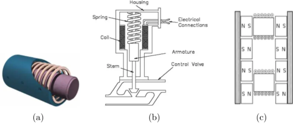
Figure 1.10: a)Example of a magnetostrictive actuator, comprising a magnetostrictive material (inside), a magnetising coil, and magnetic enclosure (outside). b) Example of solenoid actuator and application (valve control). c) U-channel linear induction actuator. The view is perpendicular to the channel axis. The two coils at center are mechanically connected, and are energized in “quadrature” (with a phase difference of 90deg (π/2 radians)). If the bottom coil (as shown)
leads in phase, then the motor will move downward (in the drawing), and vice versa.
tostrictive coefficient, which is the fractional change in length as the magnetization of the material increases from zero to the saturation value. Among alloys, the highest known magnetostriction is exhibited by Terfenol-D (Ter for terbium, Fe for iron, NOL for Naval Ordnance Laboratory, and D for dysprosium). Terfenol-D, TbxDy1-xFe2, ex-hibits strain of the order of 0.1% in a field of the order 100 kA m−1
at room temperature, and it is the most commonly used engineering magnetostrictive materia. While this phenomeno can be used for ac-tuation, it is also a “side effect” in other systmes. For instance, it is responsible for the familiar "electric hum" which can be heard near transformers and high power electrical devices.
1.3.2.7 MEMS thermal actuators
A MEMS thermal actuator is a micromechanical device that typi-cally generates motion by thermal expansion amplification. A small amount of thermal expansion of one part of the device translates to a large amount of deflection of the overall device. Usually fabricated out of doped Single Crystal Silicon or Polysilicon as a complex com-pliant member, the increase in temperature can be achieved internally by electrical resistive heating (Joules’s effect) or externally by a heat source capable of locally introducing heat. Typical kinds of thermal actuators include symmetric (bent beam) and asymmetric (bimorph) structures.
1.3.2.8 Linear induction actuators
A linear induction actuator consists of an electric motor having its stator “unrolled” so that instead of producing a torque (rotation) it produces a linear force along its length [66]. The most common mode of operation is as a Lorentz-type actuator, in which the applied force is linearly proportional to the current and the magnetic field (F = qv × B). Many designs are available. An example is reported in Fig. 1.10(c).
1.3.2.9 Hydraulic actuators
When hydraulic actuators (described above) are volume controlled, instead of pressure controlled, they might be considered as position-source actuators. For details about hydraulic actuators, the reader is referred to the preceding section.
1.3.2.10 Stepping actuators
A stepper motor is a brushless, synchronous electric motor that can divide a full rotation into a large number of steps. The motor’s posi-tion can be controlled without any feedback mechanism, as long as the motor is sized to the application. Stepper motors operate differently from DC brush motors, which rotate when voltage is applied to their terminals. Stepper motors, on the other hand, effectively have multi-ple "toothed" electromagnets arranged around a central gear-shaped piece of iron. The electromagnets are energized by an external con-trol circuit. To make the motor shaft turn, first one electromagnet is given power, which makes the gear’s teeth magnetically attracted to the electromagnet’s teeth. When the gear’s teeth are thus aligned to the first electromagnet, they are slightly offset from the next electro-magnet. So when the next electromagnet is turned on and the first is turned off, the gear rotates slightly to align with the next one, and from there the process is repeated. Each of those slight rotations is called a “step”, with an integer number of steps making a full rotation. In that way, the motor can be turned by a precise angle, as shown in Fig. 1.11. Three main types of stepper motors are available: 1)
Figure 1.11: Working principle of a stepper motor.
permanent magnet stepper; 2) hybrid synchronous stepper; 3) vari-able reluctance stepper. Permanent magnet motors use a permanent magnet (PM) in the rotor and operate on the attraction or repulsion between the rotor PM and the stator electromagnets. Variable re-luctance (VR) motors have a plain iron rotor and operate based on the principle of that minimum reluctance occurs with minimum gap,
![Figure 1: The sequence shows a parkour perform a series of jumps and articulated movements exploiting some intrinsic characteristics of the human body, such as power, robustness, explosive energy, precision etcetera [W31]](https://thumb-eu.123doks.com/thumbv2/123dokorg/7623336.116449/14.748.90.587.126.505/articulated-movements-exploiting-intrinsic-characteristics-robustness-explosive-precision.webp)