DYNAMIC SPATIO-TEMPORAL GRADIENT GENERATOR
2.1 OBJECTIVES
As stated in the previous chapter, microfluidic gradient generators have a better ability than conventional systems to produce dynamic cellular stimulation which can be also combined with physical cues. The main objective of this thesis is to design, fabricate and test an original microfluidic gradient generator capable of producing complex and dynamic chemical gradients within a specific chip area, called “chamber”, compatible with micro-/nano-engineered surfaces. The fabricated microfluidic chip will be also a preliminary proof of concept of the possibility to integrate different hybrid technologies in the same device to provide a microsystem platform for relevant biological experiments.
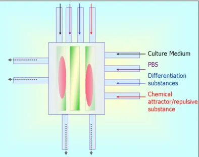
Starting from the technology recently introduced by Chung and colleagues [1], the superimposing of gradient profiles generated by fluid flows from orthogonal microchannels is exploited to build complex, user-defined 2D concentration profiles. Varying the pressure of inlet fluids and the frequency of their release through active components, called valves, a wide range of different gradient concentration profiles can be obtained. The chamber of the designed microsystem can also be provided with a specific micropatterned substrate for cell-immobilization (figure 2.1). The system
Figure 2. 1 System concept: eight inputs deliver different chemical substances into the chamber. The microfluidic layer is mounted on a micropatterned substrate, a coverglass with protein stripes (green stripes), on which the cells (pink ovals) adhere.
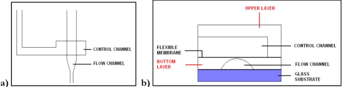
The proposed microsystem is made of two bonded layers of PDMS that are finally bonded to a glass slide. The two layers of PDMS are micropatterned. The fluid delivery of every inlet channel is finely controlled by microfabricated valve. A valve is formed when two channels cross each other at right angle (figure 2.2 a). The crossing channels belong to different PDMS layer and are separated only by a thin membrane of PDMS (about 5-6 μm). When the upper channel is pressurized, the membrane between the channels is deflected downwards, and the flow in the lower channel is reduced or shut off (figure 2.2 b).
a) b)
Figure 2. 2 a) Geometry of the active valves. b) Valve cross section. The two overlapping channels are shown: the control and the fluidic channel.
2.2 GRADIENT GENERATOR DESIGN
The chip design begins with setting the geometries of the chamber and of the channel network. Taking into account that:
− stable concentration gradients can be obtained over distances that are about 100 μm far from the injection point1
− cell body dimensions are on the order of 10 μm
− cells are sensitive to changes in their environment occurring over distances on the micron scale [2]
− area of capture with a 20x objective is 426 x 330 μm2
the chamber dimensions have been chosen to be square with side of
500 μm. Thus the chamber has an area of 0.25 mm2 with fluid delivering
channels 0.1 mm apart. This distance was selected as a trade-off between the need of superimposing of the concentration gradients produced by consecutive channels and the easy of fabrication. Control channels are designed as a consequence of the fluid channel design. It should be noted
1 It can be calculated considering the first term of equation 1.8 of Chapter 1 equal to zero
(this means that it is reached the stationary state), having known the diffusivity of the delivered substance and the concentration of substance near the injection point (C0), and
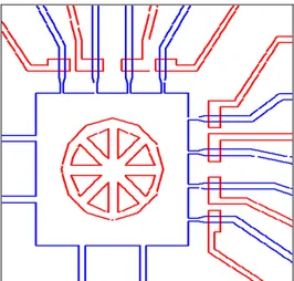
Figure 2. 3 A CAD design of the chamber where the circular red marker is used to make the hole for the inlet of the cells.
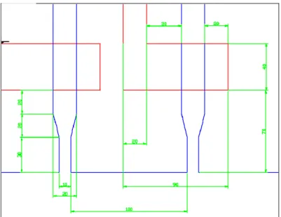
Fluidic channels at the injection point have a width of 10 μm. This value has been chosen as a trade-off between the need to have a point source injection and the ease and low cost of fabrication. Moving away from the injection point, the fluidic channels have a width of 20 μm that allows to fabricate microvalves having a low closing pressure and an acceptable closing frequency. The control channels have a width of 20 μm. Close to the chamber they become orthogonal to their respective fluidic channels and have a larger width to guarantee a good flexibility of the thin membrane which separates them. Moreover the control channels extend beyond the fluidic channels for 70 μm (figure 2.4). The fluidic and control channels have different heights (the former are 2.5 μm, the latter 10 μm) in order to allow the fluidic channel occlusion to occur more easily (figure 2.5).
Figure 2. 4 Valve design.
Figure 2. 5 3D sketch of the chamber with fluidic (pale-blue) and control (red) channels. The circular area is the shadow of hole that is made to let cells enter.
When aligning the two layers, some reference markers are required to facilitate the procedure. These markers, formed as crosses, give an idea of any rotation that might occur during the alignment operation (figure 2.6). The chip design also requires to take into account the PDMS contraction during baking. The upper layer of PDMS shrinks 1.01 % 2 during the final
Figure 2. 6 Overall chip design.
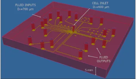
Fluids and cells are intended to enter the chip through holes connected to the channels and chamber respectively. To elucidate this concept a 3D sketch of chip is given (figure 2.7). The chip is thick, roughly 5 mm, and the holes go through the whole thickness of the chip. The diameters of the holes for fluid inputs/outputs are larger than the hole diameter used for the cell inlet (700 and 400 μm).
Figure 2. 7 3D sketch of the chip. D1 and D2 are the different diameters of holes used for fluid and cell inlets respectively.
2.3 SUBSTRATE PATTERN DESIGN
Plenty of studies in literature have demonstrated that the substrate on which cells adhere influences cell adhesion, morphology, orientation, differentiation and phagocytotic activity. It is possible to give cells some tendency in terms of the occupied area where they adhere and their motion toward a specific direction by changing the nature of substrate. These changes could involve the chemical or physical properties of the substrate, an alteration of form, or change of materials added to the initial substrate.
Chemical and physical surface patterning can be obtained by microfabrication methods, which enable to reproduce and control the cell micro-environment with unprecedented fidelity.
In this section the deposition of fibronectin, an extracellular matrix protein which induces cell adhesion, is proposed. The deposition protocol will be presented in detail in Chapter 3.
The form and dimensions of the cell-adhesive patches can control the shape and spreading of attached cells [4], thus the choice of geometry has to be reasoned considering the cell type and the kind of experiments to be performed. The first pattern here proposed consists of stripes of proteins (figure 2.8). Their widths were chosen to enhance single cell spreading, as proposed by Klein and colleagues [5] who used SH-SY5Y cells to study the formation and organisation of neural networks in vitro. This pattern could be used to observe how cells respond to chemical stimuli (attractive or repulsive substances) coming from a non adhesive area. Once the cells are aligned along the striped pattern they can be stimulated in the direction orthogonal to their alignment.
Figure 2. 8 Stripe pattern.
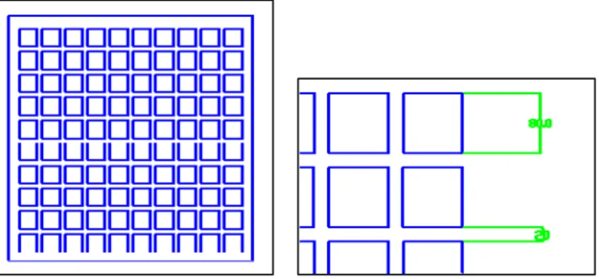
The second pattern is shaped in the form of a circuit, and it can be applied to the investigation of neurite interconnections at low plating density, as proposed by Zhang and colleagues in [6]. The pattern has the form of linear network rectangles with 80 μm width and separated by 20 μm (figure 2.9 ).
Figure 2. 9 Network pattern showing its repetitive unit.
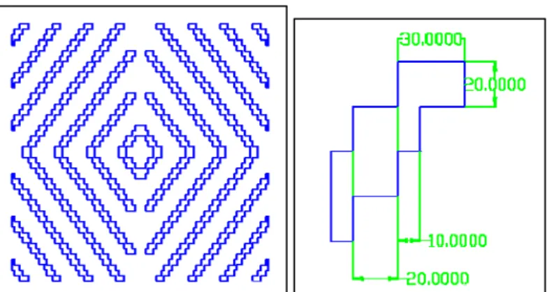
The last pattern consists of zigzag features whose purpose is to interrupt the linear motility that a cell has in the other two patterns (figure 2.10). It was proposed by Lee and colleagues [7] who observed that a continuous and complex pattern is more favourable for the stimulation of neuronal cell growth and motility.
[2] G. J. Goodhill and H. Baier, Axon guidance: Stretching gradients to the limit, Neural Comput., 10(3): 521–527, 1998.
[3] M. A. Unger, H. P. Chou, T. Thorsen, A. Scherer and S. R. Quake, Monolithic Microfabricated Valves and Pumps by Multilayer Soft Lithography, Report Science, Vol. 288, 2000.
[4] F. Didier, C. Gabor, G. H. Michelle and T. Marcus, Surface engineering approaches to micropattern surfaces for cell-based assays. Biomaterials, 27(16): 3044-3063, 2006.
[5] C. L. Klein, M. Scholl and A. Maelicke, Neuronal network in vitro: formation and organization on biofunctionalized surfaces, Journal of materials science: materials in medicine, 10: 721-727, 1999.
[6] J. Z. Venkataramani, H. Xu, Y. K. Song, H. K. Song, G. Tayhas, R. Palmore, J. Fallon and A. V. Nurmikko, Combined topographical and chemical micropatterns for templating neuronal networks, Biomaterials, 27(33): 5734-5739, 2006.
[7] J. W. Lee, K. S. Lee, N. Cho, B. K. Ju, K. B. Lee, S. H. Lee, Topographical guidance of mouse neuronal cell on SiO2 microtracks, Sensors