Alma Mater Studiorum - Università di Bologna
SCUOLA DI SCIENZE
Dipartimento di Chimica Industriale “Toso Montanari”
Corso di Laurea Magistrale in
Chimica Industriale
Classe LM-71 - Scienze e Tecnologie della Chimica Industriale
Supramolecular polyelectrolyte
complexes as mucoadhesive systems for
drug delivery applications
Tesi di laurea sperimentale
CANDIDATO
Flavia De Cecco
RELATORE
Chiar.ma Prof.ssa Maria Letizia Focarete
CORRELATORE
Chiar.mo Prof. Daniele Caretti
___________________________________________________________________________________________________________
Anno Accademico 2015-2016
ABSTRACT
The aim of this Thesis was the production and the characterization of a mucoadhesive device for drug delivery applications starting from a blend of two polyelectrolytes: polyacrylic acid (PAA) and branched polyethyleneimine (bPEI). Blends at two different compositions of the two polyelectrolytes (90:10 w/w PAA:bPEI and 80:20 w/w PAA:bPEI) were studied. Films and electrospun nanofibrous mats were fabricated and subjected to two different thermal treatments (100°C for 24h and 130°C for 24h) to crosslink the system. Morphological and thermal properties of the obtained devices were investigated through SEM analysis, TGA and DSC analysis, while FT-IR analysis was performed to get insight into the chemical structure of the blend system and the occurrence of crosslinking reaction. Moreover, gel content and swelling degree was evaluated. The mat with 90:10 w/w PAA:bPEI composition, thermally treated for 24 hours at 130°C was identified as the best system for drug delivery applications. In fact, a good crosslinking degree was achieved in the system (a gel content value of 96% was obtained) that allowed to maintain a good fiber morphology after immersion in water for 24h. This mat was therefore loaded with a 10% w/w of Econazole Nitrate, an antimicotic drug, and subjected to entrapping efficiency tests through HPLC, to investigate how efficiently the drug was loaded in the mat. Results showed that 93% of the initial weight of Econazole Nitrate added in the blend solution was loaded in the fibres. The characterization performed demonstrated that the produced device had suitable properties to work as a drug delivery system.
ABSTRACT
Lo scopo di questa tesi è stato la produzione e la caratterizzazione di un dispositivo mucoadesivo per il rilascio di farmaci, a partire da una miscela di due polielettroliti: l’acido poliacrilico (PAA) e la polietilenimmina ramificata (bPEI). Sono state studiate miscele a due diverse composizioni dei due polielettroliti (90:10 p/p PAA:bPEI and 80:20 p/p PAA:bPEI). Film e tappetini elettrofilati sono stati prodotti e sottoposti a due diversi trattamenti termici (a 100°C per 24h e a 130°C per 24h) per far avvenire la reticolazione del sistema. I dispositivi sono stati caratterizzati per quanto riguarda la morfologia e le proprietà termiche attraverso analisi SEM, analisi TGA e DSC, analisi FT-IR e test per determinare il contenuto di gel e il grado di rigonfiamento. Il tappetino
con composizione 90:10 w/w PAA:bPEI, sottoposto a trattamento termico di 24 ore a 130°C è stato identificato come il sistema migliore per applicazioni di drug delivery. Infatti, si è ottenuto un buon grado di reticolazione (contenuto in gel pari al 96%) che ha permesso di mantenere una buona morfologia delle fibre dopo l’immersione in acqua per 24h. Questo tappetino è quindi stato caricato con un 10% w/w di Econazolo Nitrato, un farmaco antimicotico, ed esposto a test di efficienza di intrappolamento del farmaco mediante HPLC, per studiare quanto efficacemente il farmaco fosse stato caricato nel tappetino. I risultati hanno mostrato che il 93% del peso iniziale di Econazolo Nitrato solubilizzato nella soluzione della miscela sia stato caricato nelle fibre. La caratterizzazione del tappetino ha dimostrato che il dispositivo prodotto ha proprietà adatte per un utilizzo come sistema per il rilascio controllato di farmaci.
INDEX
1. INTRODUCTION………...1
1.1 Polyelectrolyte complexes (PEC)………....1
1.1.1 Polyelectrolytes: introduction………..1
1.1.2 PEC assemblies………3
1.1.3 Factors influencing PEC assemblies………6
1.2 Mucoadhesive materials for drug delivery applications………..9
1.2.1 Mucoadhesion and mucoadhesive materials……….………..9
1.2.2 Mucoadhesion mechanism……….10
1.2.3 Polyacrylic acid (PAA)………..11
1.2.4 Econazole Nitrate (ECN)………...11
2. EXPERIMENTAL SECTION……….13
2.1. Materials……….……..13
2.2. Film production………14
2.2.1. 80:20 PAA:bPEI film……….14
2.2.2. 90:10 PAA bPEI film……….14
2.3. Mat production……….15
2.3.1. 80:20 PAA:bPEI mat……….15
2.3.2. 90:10 PAA:bPEI mat……….15
2.3.3. 90:10 PAA:bPEI mat loaded with 10% ECN………16
2.3.4. Electrospinning process……….………16
2.4. Drug entrapping efficiency………...18
2.5. Characterization Techniques……….…...18
2.5.1. Thermogravimetric Analysis (TGA) ………...18
2.5.2. Differential Scanning Calorimetry (DSC)……….……18
2.5.3. Scanning Electron Microscopy (SEM)………..19
2.5.4. Fourier transform infrared spectroscopy (FT-IR)………..19
2.5.5. Gel Content and Degree of Swelling……….20
2.5.6. HPLC Analysis………..20
4. RESULTS AND DISCUSSION………22
4.1. Optimization of polyacrylic acid (PAA) electrospinning and crosslinking via 1,4-diaminobutane (DAB)………..22
4.2. Blends of PAA and branched polyethyleneimine (bPEI)……….27
4.2.1. Pure components characterization……….27
4.2.2. Optimization of blend production procedure……….31
4.2.2.1. 80:20 PAA:bPEI film……….32
4.2.2.2. 90:10 PAA:bPEI film……….34
4.2.3. Preparation and characterization of electrospun mats from blends at different compositions of PAA and bPEI……….36
4.2.3.1. 80:20 PAA:bPEI mat……….37
4.2.3.2. 90:10 PAA:bPEI mat……….41
4.2.4. Production of fibrous mat loaded with Econazole Nitrate (ECN)……….45
5. CONCLUSIONS………48
1
1. INTRODUCTION
Drug delivery systems (DDS) have gained much interest in the last years due to their useful ability to avoid negative effects linked to conventional drug administration routes. In fact, common methods present several disadvantages for the human body because the drug distributes throughout the body and so it can reach a variety of sites at which it may be inactive or harmful, resulting in unwanted side-effects1. Drug delivery systems have been used for reducing side effects and enhancing therapeutic efficacy: they can improve the effectiveness of a drug by containing the drug concentration and allowing its targeting and localization at a specific site. Many drug delivery systems are based on so-called mucoadhesive polymers. The interaction between the mucus and mucoadhesive polymers is a result of physical entanglement and secondary bonding, mainly H-bonding and van der Waals attraction2. In previous works, Nho et al. and Park et al. find out that polyanions with a high charge density, such as polyacrylic acid (PAA), were good mucoadhesive materials: indeed, carboxyl groups can interact with mucin molecules in their protonated form, and this suggests that the interaction may be due to hydrogen bonding2,3. PAA is water-soluble, so a crosslinking of the system is needed to allow the correct working of the DDS: at this purpose, in this work, branched polyethylenimine (bPEI) is added to solutions of PAA to obtain water stable blends with different compositions. Since PAA and bPEI are polyelectrolytes, this work concerns the assembly and the study of mucoadhesive polyelectrolyte complexes (PEC) for DDS.
1.1. Polyelectrolyte complexes (PEC) 1.1.1 Polyelectrolytes: introduction
Polyelectrolytes are water-soluble molecules with properties that are halfway between the ones of electrolytes and polymers and are the synthetic counterpart of important natural molecules like nucleic acids, proteins and others. They have many charged or neutral but ionisable groups along the macromolecular chain, almost one in every repeating units, that allow them to adopt ionic behaviours. They can be classified in polyacids (polyanions) and polybases (polycations) depending on their charge, or in weak and strong polyelectrolytes depending on the degree of ionisation. Table 1.1 shows some of the most common polyelectrolytes known.
2
Table 1.1 Structures and abbreviations for common polyelectrolytes 8
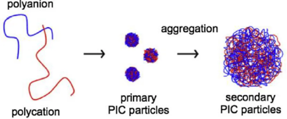
The presence of many charges in the polymeric backbones leads to the establishment of strong ionic interactions that allow the polyelectrolytes to co-assembly in supramolecular architectures. These assemblies are prepared by mixing polycation and polyanion solutions in nonstoichiometric ratios and are often referred to as polyelectrolyte complexes (PEC) or polyion complexes (PIC): their structure, properties and functions are strongly dictated by the electrostatic forces and the synthetic route. Recent works suggest that the mechanism of formation of PECs consists of two steps: nucleation of polyions to obtain primary molecular complexes and consecutive aggregation of other polyions chains to get secondary particles4 (Figure 1). Müller et al. affirmed that the formation of primary particles is rapid and concerns only one or a few polyanion/polycation pairs held together by long-range electrostatic interactions5. Since counterions are released from polyelectrolyte backbones, it results clear that the gain in entropy is the driving force of this first step. Former particles then aggregates in secondary ones, consisting of around 100 primary PEC particles held together by short-range dispersive interactions5.
3
Figure 1. Schematic presentation of the processes occurring during mixing of polyelectrolytes and
formation of PIC particles6
PECs are excellent candidates for biomedical applications and their self-assembly capability allows the formation of interesting supramolecular assemblies with good drug delivery properties6.
In this work, two polyelectrolytes, polyacrylic acid (PAA) and branched polyethylenimine (bPEI), have been studied as components of a blend for the production of mucoadhesive drug delivery systems. PAA is the principal component of the blend produced in this work, and gives the mucoadhesion properties, while bPEI works as ‘crosslinking agent’ to make the device non water-soluble.
1.1.2 PEC assemblies
The morphology of the PEC complexes depends on the types of polyelectrolytes employed and on the way these are assembled6. H. Yoon et al. have noticed that PECs can aggregate with several mechanisms, producing different typologies of assemblies: nanoparticles, micelles, multilayers and hydrogels8
.
Nanoparticles. PEC particles consist of a neutral core containing 1:1 mixtures of
oppositely charged polymers, surrounded by a shell of excess charged chains (Fig. 2). The outer charged layer envelop the inner polyelectrolyte allowing better stability and dispersion of the aggregates: its absence would lead to a destabilization of particles in solution, since they would face flocculation due to the attraction between neutral aggregates.
4
Figure 2. PEC nanoparticles assembly and subsequent counterion release6
Micelles. Generally, micelles are composed of hydrophobic tails surrounded by polar
head groups in contact with aqueous environment, while the high molecular analogues to such molecules, for the synthesis of PEC reverse micelles are block copolymers, and they are very useful in biomedical applications. Spontaneous assembly of PEC reverse micelles is therefore achieved by mixing two block copolymers composed of neutral, hydrophilic block and a polyanionic or polycationic block8 (Fig. 3). It is interesting to
notice that PEC that constitute the micelle’s core is a promising vehicle for drug delivery through the body8.
5
Multilayers. Polyelectrolyte multilayers (PEMs) are thin assemblies created by the
directed complexation of oppositely charged polyelectrolytes and assembled by the layer-by-layer (LbL) technique9.
Figure 4. Scheme of layer-by-layer deposition technique 8
This simple technique consists of repeated immersion of a substrate into oppositely charged polyelectrolyte solutions in succession. In these assemblies, polyelectrolytes interact not only through electrostatic interactions, but also with hydrogen bonds10. PEMs may undergo crosslinking to improve their mechanical stability and robustness, and this treatment usually occurs via thermal process. Most studies deal with polyelectrolytes in their full charged state, but through the years, the attention has also been paid to multilayers of weak polyelectrolytes. In these cases, it is in fact possible to systematically vary the linear charge density of the polymer via simple adjustments of pH so that it results possible to alter in a controlled way the charge of the weak polyelectrolyte during the process12. These assemblies are established biomaterials that find applications as drug delivery systems thanks to their characteristics and ease processability.
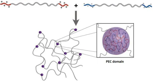
Hydrogels. Another important assembly are hydrogels. Although the major part of the
mass of a hydrogel consists of water, the mechanical properties are those of a solid thanks to a global 3D-network of bonds. Traditionally this network is made of covalent bonds, but these are limited in their reversibility and responsiveness, so hydrogels based on electrostatic interactions have been introduced8. Physically formed hydrogels are the substitutes of covalently formed ones that have the quality of being more dynamic and useful as materials. N. Hunt et al. note that hydrogels stabilized by non-covalent associations can truly excel as three-dimensional cell mats13. When two oppositely charged copolyelectrolytes come into contact, their charged regions form complexes coacervate domains that crosslink the hydrophilic part of the chain (Fig. 5).
6
Figure 5. Supramolecular hydrogel8
1.1.3 Factors influencing PEC assemblies
Polyelectrolytes assembly processes are more complicated than the ones of non-electrolyte polymeric systems. The reason of this evidence is that there is a wide number of parameters that dictates the way the assembly happens, but it is certainly possible to say that electrostatic interactions provide a simple pathway to high complex structures8. Unlike strong polyelectrolytes, weak polyelectrolytes are more sensitive to the variation of parameters, especially to pH changes. For weak polyelectrolytes, the amount of charged sites varies as a function of pH and the charging process can be controlled in order to modify some properties and take advantage of the polyelectrolyte for its potential applications. From weak polyelectrolytes it is possible to produce systems with a rich suite of properties because their behaviour is sensitive to pH, ionic strength and other parameters that are now going to be introduced 14,15. In order to have well disperse
and stable polyelectrolyte particles, the factors that need to be simultaneously optimized during the formulation are:
Process parameters: mixing ratio, mixing order;
Chemical parameters: polymer concentration, pH, ionic strength; Structural parameters: polymer molecular weight, charge density. Usually, stable complexes are prepared at high dilution and low ionic strength.
7
Charge density and molecular weight
It has been noticed that the number of charged groups per polymer chain influence the stability of the PEC particles and above an upper critical length, polyelectrolytes form stable complexes, so the simplest way to increase it and form stable complexes, is to have polyelectrolytes with increased MW. Charge density is also affected by the topology of the polymer: with respect to linear polyelectrolytes, branched analogues can electrostatically crosslink a wide number of oppositely charged chain, creating a strong and tight polymeric network.
Polyelectrolyte concentration
As already reported in previous articles, polyelectrolyte concentration is one of the parameters that affects the assembly mechanism of PECs5,6. In particular, Zintchenko et
al. find out that dispersed PEC nanoparticles can only be formed in polyelectrolyte
mixtures below a critical concentration. Above this critical value of concentration, the system flocculates or precipitates, so it is possible to say that high concentrations of starting polyelectrolytes lead to the formation of complexes with poor colloidal stability16.
pH
As mentioned before (paragraph 1.1.2 “Micelles”) pH strongly affects the charge density of weak polyelectrolytes, while strong polyelectrolytes are not influenced by this parameter. Changing in pH values lead to changing in deprotonation/protonation degree of weak polyelectrolytes. This modification in charge density depends on the pKa values
of the species involved. For example, a polyacid will result deprotonated only at a small extent if the pH value of the environment is lower than its pKa value, while in the same
condition, a polybase will be all protonated. It is therefore predicable that, since the chosen pH value to assemble two polyelectrolytes affects their charge densities, it will govern the process leading to specific assemblies.
8
Ionic strength
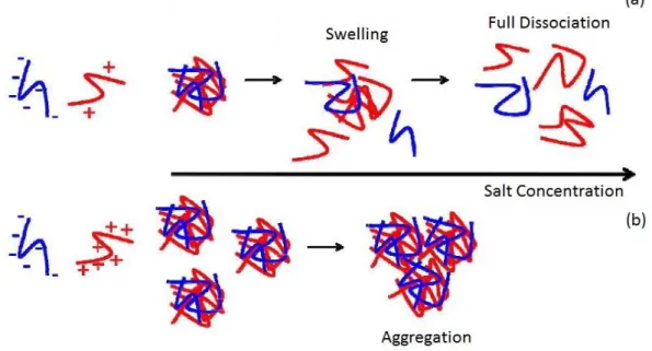
The addition of a moderate amount of small electrolytes can promote the self-assembly of PIC particles by shielding the intramolecular charge repulsions of polyions chains, thus increasing chain flexibility, making easier the conformational adaptation of chain in coil structures and increasing the ability to self-assemble particles. On the other hand, high salt concentrations can lead to strong electrostatic screening between polyelectrolytes, thus avoiding the nucleation of PIC particles (Fig. 6a). Therefore, the ionic strength of the medium must be carefully selected to successfully assemble PIC particles. In conditions of low electrolyte concentration, primary particles are stabilised against coagulation, but increasing the ionic strength, the repulsion between particles shells decreases, causing the secondary aggregation of the primary particles (Fig. 6b). The level of aggregation so increases again and it appears clear that a minimum of ionic strength value has to be established to obtain a stability of the solution. Anyway, a prediction of the effects of the presence of salt during complex formation is very difficult, because of the complicated processes of structure formation related also to the specific characteristics of the polyelectrolyte components16.
9
Mixing ratio and mixing order
The term “mixing ratio” means the proportion of the ionisable groups of opposite charges in the polyelectrolytes that are mixed. As already explained, pH affects the degree of ionisation of the chains so for a same mixture of polyelectrolytes, the effective mixing ratio will vary with pH. The reaching of a stabile PEC particle solution pass through the employment of non-stoichiometric mixing ratios: this condition stabilises the shell of the primary complexes formed, leading to a particle characterised by an absolute charge equal to the one of the component in excess. Therefore, at mixing ratios close to neutrality, unstable complexes are formed and flocculate because of electrostatic attraction.
It is then very important to understand how mixing order, influenced by mixing ratio, affects the assembly of these complexes, and once again electrostatic interactions play a critical role in this process. If the majority component is added to a solution of the minority one, there will be a point at which the two opposite charges are equimolar and induce the aggregation and precipitation of the complexes. Instead, if the minority component is added to a solution of the majority one, the system might result more equilibrated since the neutralisation of the opposite charges will never figure out because there will always be an excess of the majority component charge. This last condition is so taken as the favourite one5,6.
1.2 Mucoadhesive materials for drug delivery applications 1.2.1 Mucoadhesion and mucoadhesive materials17
Mucoadhesion is the correspondent of bioadhesion, when the substrate of attachment is mucus or mucous membrane. In general, bioadhesion is the phenomenon by which interfacial forces held together two materials, for extended periods. Mucus is a gel-like material composed of glycoprotein, lipids, inorganic salts and water. Water represents the wider part of mucus mass (95%) making it a highly hydrated system with cohesive and adhesive properties, given by the glycoproteic component. Particular interest is devoted to hydrophilic macromolecules containing a wide number of groups able to form hydrogen bonds. These materials are activated to mucoadhesion by moistening and typical examples are carbomers, chitosan and cellulose derivatives.
10
Mucoadhesive materials form high viscosity and pH sensitive aqueous solutions at low concentrations. The improved viscosity of these solutions is due to the nature of mucoadhesive materials: as definition, they are hydrophilic macromolecules containing a wide number of groups able to form hydrogen bonds. The formation of these bonds lead to an increment in the solution viscosity.
Figure 7. Some examples of mucoadhesive materials
1.2.2 Mucoadhesion mechanism
The basic principle of mucoadhesion phenomenon is that molecules bond across the interface, and this event can occur in different ways:
Ionic bonds; Covalent bonds; Hydrogen bonds; Van der Waals bonds.
The mechanism of mucoadhesion is composed of two steps. Cellulose
11
Contact stage
In this step the two membranes involved, the mucoadhesive one and mucous, get in intimate contact, in a process known as “wetting”.
Consolidation stage
This next step provide for the prolongation of adhesion thanks to physicochemical interactions that occur to consolidate and strengthen the adhesive connection.
1.2.3 Polyacrylic acid (PAA)
Polyanions with high charge densities have been identified as good mucoadhesive materials, and one of the most important polymer belonging to this class is PAA. At acidic pH values, carboxyl groups present in PAA macromolecular chains are protonated and are able to interact with mucin through hydrogen bonds. PAA chains have also great flexibility, characteristic that leads this polyelectrolyte to be one of the best mucoadhesive material.
Since mucoadhesive polymers have optimal characteristics for the production of drug delivery systems, it follows that polyacrylic acid-based drug carriers are among the most successfully ones to be used in mucoadhesive drug delivery systems.
1.2.4 Econazole Nitrate (ECN)
Econazole (EC) is an imidazole based antifungal agent commonly used in pharmaceutical formulation as nitrate salt (ECN) to improve its very limited solubility in water.
12
It is commonly used for the treatment of topical fungal infections caused by Candida
albicans in many parts of the body, such as mouth, eyes and vagina. Topical econazole is
available as cream formulation, characterised however by inadequacy in the administration phase. In fact, 90% of Econazole Nitrate topically applied as cream remains on the skin surface. The low solubility of Econazole limits its concentration at the desired site of action and reduces permeation rate, so it has usually to be applied for several weeks. To avoid and solve such problems, localised mucoadhesive dosage forms may represent a suitable formulation design to improve the bioavailability of the drug and simplify the patient treatment. At this purpose, a drug delivery system with the ability to entrap a good quantity of drug, and release it in a specific time-window, represents a valid and interesting alternative18-21.
13
2. EXPERIMENTAL SECTION
2.1 Materials
The polymers used for the production of the blends are two polyelectrolytes: polyacrylic acid (PAA) with an average molecular weight of 450,000 g/mol, and branched polyethylenimine (bPEI) with an average molecular weight of 25,000 g/mol, (Fig. 9) both purchased from Sigma-Aldrich.
PAA appears as a hygroscopic and fine white powder; bPEI appears as a transparent and very viscous liquid. The solvents for the preparation of the blends were deionized ultrapure H2O (Milli-Q Millipore 18.2 MΩ/cm, Bedford, MA, USA) and EtOH
purchased from Sigma Aldrich. In steps requiring the acidification of a bPEI aqueous solution, it was used, for the purpose, a solution of HCl 37% w/w by Sigma-Aldrich. For the preparation of a pH 7.4 phosphate buffer (PB), K2HPO4 (Sigma-Aldrich) and Milli-Q
water were used. The drug to be delivered was Econazole Nitrate (Carlo Erba) (Fig. 10): it is a fine white powder with a molecular weight of 381.68 g/mol. All reactants and solvents were used without any further purification step or treatment.
Figure 9. Structures of PAA (a) and bPEI (b)
(a) (b)
14
2.2 Film production
2.2.1 80:20 PAA:bPEI film
80:20 PAA:bPEI film was obtained from 5 mL of a solution of 80:20 PAA:bPEI blend (total concentration 5% w/v) in a mixture of EtOH:H2O 70:30. The blend solution was
prepared by mixing two separate solutions: an ethanol PAA solution and an aqueous bPEI solution. The first was prepared dissolving 200 mg of PAA in 3,5 mL of EtOH: PAA did not dissolve instantaneously, so the solution was left under stirring for about 1 hour. Meanwhile, 50 mg of bPEI were weighed and put in a vial with 1.5 mL of Milli-Q H2O and left under stirring to dissolve.
To avoid precipitation of the final blend, when mixing the two components solutions, the amine groups of bPEI have to be protonated. pH of the bPEI solution was therefore measured with a pHmeter, and resulted being ≈11. Primary, secondary and tertiary amine groups in bPEI have a pKa of 4.5, 6.7 and 11.6 respectively, so in order to reach the protonation of all amines, pH value needed to be lowered below the pKa value of the three types of amines present in bPEI chains, and it was decided to lower the pH down to 1. This passage was carried out adding small volumes of HCl 37% w/w and monitoring the gradual change in pH values with a continuous measurement with the pHmeter, until the reaching of the desired value. Once concluded the acidification step, bPEI solution was slowly added to the PAA solution under stirring, to form the final blend. The resulting system appeared as a very viscous solution and was used to produce a film with the film casting technique: it was deposited on a polystyrene petri dish and left at the air overnight to let the solvent evaporate and allow the formation of the film (Fig. 11). Once all the solvent evaporated, the film was collected and put in an oven at 130°C for 24 hours to let the crosslinking take place.
2.2.2 90:10 PAA:bPEI film
90:10 PAA:bPEI film was obtained from 5 mL of a solution of 90:10 PAA:bPEI blend (total concentration 5% w/v) in a mixture of EtOH:H2O 70:30. The solution was prepared
following the same procedure adopted for the 80:20 PAA:bPEI reported above, except for the quantities of reactants used. In this passage, 225 mg of PAA were weighed in a crystallizer containing 3,5 mL of EtOH, and left dissolving under stirring for about an hour. Meanwhile, 25 mg of bPEI where dissolved in 1.5 mL of Milli-Q H2O and HCl
15
37% w/w was added in a controlled way as described in the paragraph above in order to lower the pH from the value of 11 to 1. The blend solution was then deposited on a polystyrene petri dish and left apart to let the solvent evaporate to obtain a film. After solvent evaporation, the film was collected and put in an oven at 130°C for 24 hours, to let the crosslinking take place.
Figure 11. Film obtained by film casting technique
2.3 Mats production
2.3.1 80:20 PAA:bPEI mat
Electrospun mat of the blend with composition 80:20 PAA:bPEI was produced starting from a solution prepared in the same way as the one used for film preparation (paragraph 2.2.1). The technique used to produce such device is electrospinning. Once obtained the mat, it was put in an oven for 24 hours at 130°C to let the crosslinking take place.
2.3.2 90:10 PAA:bPEI mat
Electrospun mat of the blend with composition 90:10 PAA:bPEI was produced starting from a solution prepared in the same way as the one used for film preparation (paragraph 2.2.2). The solution was subjected to an electrospinning process to obtain the fibrous mat desired. Once obtained, it was put in an oven for 24 hours at 130°C to let the crosslinking take place.
16
2.3.3 90:10 PAA:bPEI mat loaded with 10% ECN
Mat with composition of 90:10 PAA:bPEI containing 10% of ECN was produced starting from a solution prepared in the same way as the one used for the assembly of the film (paragraph 2.2.2), but econazole nitrate was loaded in the blend. At this purpose, before mixing the two solutions of PAA in EtOH and bPEI in acidified H2O, 25 mg of ECN
(10% w/w with respect to the blend) were added to the ethanol solution of PAA and everything was left under stirring to allow the solubilisation of the drug. Once that the solubilisation happened, the bPEI aqueous solution was added to the PAA solution containing ECN. The solution obtained underwent electrospinning process in optimized conditions and the produced mat was put in an oven for 24 hours at 130°C to let the crosslinking take place.
2.3.4 Electrospinning process
The electrospinning equipment was composed of several parts:
a high-voltage generator (Spellman SL50 * 10, maximum voltage 50 kV, positive polarity, maximum power 10 Watt);
a dosing pump (KDScientiicTM series 200) in which a syringe containing the polymeric solution is placed. The pump allows to adjust the flow rate of the solution from 0.001 mL/h to 70.57 mL/min;
a Teflon tube connected to a metal needle;
a collector put at a variable distance from the needle.
17
The apparatus is placed in a thermostatic chamber (glove box) that allows operating in controlled conditions of temperature and relative humidity (Iteco Eng., Ravenna, Italy, 100 x 75 x 100 cm).
For the production of the mats presented in sections 3.1 and 3.2.3, specific electrospinning conditions were applied to the process (Table 2.1).
Table 2.1. Electrospinning process conditions
PAREMETER VALUE
Potential (ΔV) 18 kV
Syringe diameter 14,6 mm
Needle internal diameter 0.52 mm
Flow rate 1 mL/h
Distance needle-collector 20 cm
Temperature ≈ 20°C
RH ≈ 40%
An example of mat obtained through electrospinning technique by using experimental conditions reported above, is shown in Figure 13.
18
2.4 Drug entrapping efficiency (EE%)
The aim of conducting entrapping efficiency test (EE%) is to understand in which percentage the drug has been loaded into the mat during its production, with respect to the initial weight of the drug, dissolved in the solution. The procedure to perform this test was the following. A part of the mat was submerged in 100 mL of pure EtOH and sonicated for 4 hours. After this passage, a volume of 1.5 mL of the solution was picked up and filtered on 0.2 µm nylon filters. The solution obtained was then injected in the HPLC to undergo an HPLC analysis and monitor the presence of Econazole Nitrate in the mat. This procedure was performed in triplicate to have a better result in entrapment efficiency.
2.5 Characterization Techniques
2.5.1 Thermogravimetric Analysis (TGA)
Thermogravimetric analysis were conducted with thermogravimetric analyser Q500 (TA Instruments, New Castle, Delaware, USA). All the experiments were carried out in an N2
atmosphere created by a N2 flow purged in the balance. Samples of 5-10 mg were
subjected to a thermal treatment up to 900°C, with a heating ramp of 10°C/min.
2.5.2 Differential Scanning Calorimetry (DSC)
A differential scanning calorimeter Q100 (TA Instruments, New Castle, Delaware, USA), equipped with a Liquid Nitrogen Cooling System (LNCS) was used. Analysed samples weighted 5-10 mg and were submitted to the following thermal program:
a first scan from -80 °C to 140 °C at a rate of 20 °C/min; rapid cooling to -80°C.
These two steps were repeated so that the entire analysis comprehended three heating cycles and two cooling cycles. Starting and final temperature of the analysis were chosen on the base of Tg values of the two components reported in literature (Tg bPEI=-55°C; Tg PAA=130°C) and their degradation temperatures.
19
2.5.3 Scanning Electron Microscopy (SEM)
To perform SEM analysis it was used a Philips 515 Microscope with an accelerating voltage of 15 kV. Samples were fixed on aluminium stubs as supports with conductive bi-adhesive tape. This passage allows the non-conductive polymeric sample to be suitable for this kind of analysis. Next, stubs were coated with gold with a metallization process and then submitted to the analysis. Images were acquired and analysed with EDAX Genesis software. For all the produced mats, around 300 diameters of different fibres were sampled and measured and the mean diameters with associated standard deviations are reported in the Results and Discussion section of this thesis.
2.5.4 Fourier transform infrared spectroscopy (FT-IR)
FT-IR analysis were conducted with an ALPHA FTIR Spectrometer by Bruker combined with QuickSnap™ sampling modules and interfaced with OPUS/Mentor software. All the analysis were performed in transmittance mode and the samples were prepared in different ways.
Mats: FT-IR analysis of mats were simply performed placing a portion of the mat
between two NaCl tablets and located in the designated sample holder. Before the real analysis, a background spectrum of the NaCl tablets without sample was registered.
Films and powders: FT-IR analysis of films and powders (ECN) were conducted on
KBr and sample tablets. These tablets were produced grinding together 200 mg of KBr (Sigma Aldrich) and 50 mg of the sample. For the production of KBr tablets containing the films, the sample was cut with N2 liquid to make the grinding easier. The mixed
powders then were placed under a pressure of 20 bar for 4 minutes with a hydraulic press. The obtained tablets were placed in the designated sample holder and the analysis then were performed.
bPEI: FT-IR analysis of bPEI were performed mixing the branched amine with nujol or
paraffin, and placing the blend between two NaCl tablets, then placed in the specific sample holder.
20
2.5.5 Gel Content and Degree of Swelling
Gel content and degree of swelling tests were conducted on the thermal treated devices to investigate in which entity crosslinking occurred. The tests were performed in triplicate with the following procedure. Mats and films were cut to obtain small samples to submit to test; every dry piece was weighted after thermal treatment, obtaining the starting mass (m0). The next step was the immersion of the samples in 20 mL of Milli-Q H2O for 24
hours. After the 24 hours of immersion, samples were removed from water and weighted without drying it, to obtain the mass of the swollen sample (ms). After this passage, the
samples were left drying at the air, overnight. Next day, once the water was all removed from the samples, they were weighted again, to obtain the final residue mass (md). The
data collected were used to calculate gel content (G) and swelling (Q) with the following formulas. 𝑮 = 𝑚𝑑 𝑚0 × 100 𝑸 = 𝑉𝑠 𝑉𝑑 = 1 + 𝜌2 𝜌1 ( 𝑚𝑠 𝑚𝑑− 1)
Where Vs is the volume of the swollen sample; Vd is the volume of dried sample; ρ1 is
the density of H2O = 1 g/mL; ρ2 is the density of PAA = 1.3 g/mL.
2.5.6 HPLC Analysis
All chromatographic analyses were performed on HPLC system (Shimadzu, JAPAN) equipped with two pumps (10ADvp, Shimadzu, Japan), an UV-Vis detector (SPD-10Avp, Shimadzu, Japan), an autosampler (SIL-20 A, Shimadzu, Japan) and a 20 µL loop. In order to obtain an optimal separation of Econazole Nitrate a C18 column (15cm x 4.6 mm x 5 µm, Luna Phenomenex) was employed. Analytical method was developed using a mixture of MeOH/Ammonium phosphate buffer pH 2.5 (20 mM) 75:25 v/v as mobile phase, a flow rate of 1 ml/min and a run time of 10 min. Econazole nitrate showed a retention time of 5.4 min.
21
3. AIM OF THE THESIS
The present Thesis focuses on the study of polyelectrolyte-based materials as mucoadhesive systems for drug delivery applications. Among polyelectrolytes, polyacrylic acid (PAA) is considered one of the best mucoadhesive polymer and therefore in the present project it was selected to fabricate drug loaded electrospun devices. As a first step, an electrospun mat of crosslinked PAA was prepared and characterized. In order to optimize the stability in water of the PAA electrospun mat the binary system PAA/branched polyethyleneimine (bPEI) was studied. In this Thesis the properties of PAA and bPEI blends and their crosslinking was studied in order to obtain water stable films and electrospun mats. PAA and bPEI are two polyelectrolytes that are expected to form stable complexes. Indeed, polyelectrolytes have charges on their polymeric backbones that lead to the establishment of strong ionic interactions that allow the co-assembly in supramolecular architectures through polyelectrolyte complexes (PEC). PECs are excellent candidates for biomedical applications and in particular for drug delivery. In literature, PAA/bPEI blend system have been not much investigated, so this work aims to bring a contribution to a quite unexplored and challenging topic. The rationale behind this research project was that PAA and bPEI chains could crosslink through the formation of stable interactions, such as ionic interactions typical of polyelectrolyte systems, hydrogen bonds or covalent amide bonds deriving from the reaction of the carboxylic acid functional group of PAA with the amine functional group of the bPEI.
Blends at two different compositions of the two polyelectrolytes (90:10 w/w PAA:bPEI and 80:20 w/w PAA:bPEI) were studied. Films and electrospun nanofibrous mats were fabricated and their chemical, morphological and thermal properties were investigated. The obtained devices were then subjected to two different thermal treatments (100°C for 24h and 130°C for 24h) in order to stabilize their structure through crosslinking and avoid solubilization when immersed in water. The mat identified as the best system for drug delivery applications will therefore be loaded with a 10% w/w of Econazole Nitrate, an antimicotic drug, and subjected to entrapment efficiency tests in order to investigate how successfully the drug will be loaded in the fibrous mat.
22
4. RESULTS AND DISCUSSION
The present Thesis focuses on the study of polyelectrolyte-based materials as mucoadhesive systems for drug delivery applications. As mentioned in the Introduction (paragraph 1.2.3) polyacrylic acid (PAA) is considered one of the best mucoadhesive polymer and therefore in the present project it was selected to fabricate drug loaded electrospun devices.
As a first step, an electrospun mat of crosslinked PAA was prepared and characterized.
4.2 Optimization of polyacrylic acid (PAA) electrospinning and crosslinking via 1,4-diaminobutane (DAB)
The optimization of the electrospinning process of a PAA solution was performed through a series of steps as described below. First, a solution 1% w/v of PAA in ethanol was prepared, but in the electrospinning process it was collected a powder-like material and not fibers. This result was attributed to a too low solution concentration. Then a 4% w/v of PAA solution in ethanol was prepared and subjected to the electrospinning process, fibers were obtained but the electrospinning process was not stable and the obtained mat was not homogenous. These trials led to understand that about 4% w/v could be the right concentration of the solution but, in order to optimize the process, the solvent mixture had to be changed. A trial with water instead of ethanol as solvent was made, but the obtained fibers resulted irregular and full of beads. In the last attempt a solution 4% w/v of PAA in a mixture 70:30 v/v EtOH:H2O was processed by using the
following final electrospinning conditions:
- ΔV: 18 kV; - Syringe diameter: 14.6 mm; - Distance needle-collector: 20 cm; - Flow rate: 1 mL/h; - Temperature ≈ 20°C; - RH ≈ 40%.
23
A mat with regular and defect-free fibers (mean diameter 500 nm) was obtained, as shown in the SEM micrograph reported in Figure 14.
Figure 14. SEM image at x1000 (main) and x4000 (inset) of PAA mat electrospun from a 4% w/v solution
in a 70:30 EtOH:H2O mixture
The thermal properties of the mat were characterized by means of TGA and DSC.
TGA analysis (Figure 15) shows an initial weight loss step starting at room temperature and with a temperature of maximum weight loss rate (Tmax) of about 50°C, that was
assigned to water evaporation from the sample. This result was expected due to the high hydrophylicity of the polymer. Thermal degradation of PAA occurred in two main weight loss steps at Tmax of around 300°C and 420°C. It is worth to point out that the
polymer starts losing weight quite earlier, at a temperature of about 150°C.
The DSC curve of the PAA mat is reported in Figure 16. As expected, the polymer presents only the glass transition at a temperature (Tg) of about 130°C, confirming that
24
Figure 15. TGA analysis of PAA mat electrospun from a 4% w/v solution in a 70:30 EtOH:H2O mixture
Figure 16. DSC curve (second scan at 20°C/min) of PAA mat electrospun from a 4% w/v solution in a
70:30 EtOH:H2O mixture
The electrospun mat was also analyzed by means of IR analysis. In the IR spectrum, shown in Figure 17, the peaks characteristics of PAA are identified, as reported in Table 4.1.
25
The peak at 3530 cm-1 is ascribable to the stretching mode of free –OH, while the one at
3096 cm-1 is ascribable to stretching modes of bonded –OH. Hydrogen bonds, in fact,
cause a shifting of the peak to lower frequency values and also causes an increase in its intensity and a broadening of the peak.
Figure 17. IR spectrum of PAA mat electrospun from a 4% w/v solution in a 70:30 EtOH:H2O mixture
Table 4.1. Peak assignment of IR spectrum reported in Figure 17
Wavelength (cm-1) Functional Group Type of vibration
3530 -O-H free Stretching
3095 -O-H bonded Stretching
2677 -C-H- Stretching
1692 -C=O Stretching
1452-1415 -C-H- Bending
1248-1117 -C-C- Stretching
908-804 -C-H-/-C-C- Rocking
Polyacrylic acid is a water soluble polymer, therefore crosslinking is needed when it must be water resistant for specific applications.
26
To crosslink electrospun PAA mat, diaminobutane (DAB) was added to the PAA solution before electrospinning. Two solutions of PAA at 4% w/v in a 70:30 EtOH:H2O
mixture were prepared, by adding 5% w/w and 10% w/w of DAB with respect to the PAA weight. Part of the mat obtained after the electrospinning process underwent a thermal treatment at 130°C in an oven for 1h, in order to activate the crosslinking reaction. This temperature was selected on the basis of previous results23.
In addition to electrospun mat, films of PAA containing 5% w/w and 10% w/w of DAB were prepared through the solvent casting method. Part of the obtained films underwent the same thermal crosslinking treatment of the mat, at 130°C in an oven for 1h.
In order to check the success of the crosslinking procedure, solubility tests were performed according to the procedure reported in the experimental part, on both the electrospun mats and the films. Results, shown in Figure 18, proved that DAB does not work efficiently enough as crosslinker. Thermally treated PAA film with 5% w/w DAB became a hydrogel (Fig. 18b) when immersed in water, whereas thermally treated PAA mat with 10% w/w DAB, maintained its macroscopic appearance and integrity (Fig. 18d). However, the PAA mat lost its fibrous morphology, as can be appreciated by looking at the SEM images of the mat after the solubility test (Fig. 19).
These preliminary results encouraged the investigation of a better crosslinker agent, that was identified in branched polyethylenimine (bPEI).
Figure 18. PAA film containing 5% w/w DAB thermally treated, pre (a) and post (b) solubility tests; PAA
mat with 10% w/w DAB thermally treated, pre (c) and post (d) solubility tests (d)
(c)
(b) (a)
27
Figure 19. SEM image at x1000 (main) and x4000 (inset) of PAA electrospun mat with 10% w/w DAB
after thermal treatment and solubility test
4.3 Blends of PAA and branched polyethyleneimine (bPEI)
The main aim of this Thesis was to study the properties of PAA and bPEI blends and their crosslinking in order to obtain water stable films and electrospun mats.
PAA and bPEI are two polymers belonging to the family of polyelectrolytes and it is expected that they form stable complexes. Indeed, polyelectrolytes have charges on their polymeric backbones that lead to the establishment of strong ionic interactions that allow the co-assembly in supramolecular architectures (PEC)4. PECs are excellent candidates for biomedical applications with good drug delivery properties6. In literature, PAA/bPEI blend system have been not much investigated, so this work aims to bring a contribution to a quite unexplored and challenging topic. The rationale behind this research project was that PAA and bPEI chains could crosslink through the formation of stable interactions, such as ionic interactions typical of polyelectrolyte systems, hydrogen bonds or covalent amide bonds deriving from the reaction of the carboxylic acid functional group of PAA with the amine functional group of the bPEI.
4.3.1 Pure components characterization
Branched polyethylenimine:
TGA analysis (Fig. 20) shows that bPEI starts its degradation process at 200°C and the most significant degradation steps are centred at Tmax around 320°C and 380°C.
28
The DSC analysis (Fig. 21) shows only the Tg, at about -51°C, and this means that bPEI
is an amorphous polymer with a low glass transition temperature, in agreement with literature results24.
Figure 20. TGA curve of pure bPEI
29
FT-IR spectrum of pure bPEI is shown in Figure 22, and peak assignment is listed in Table 4.2.
Figure 22. FT-IR analysis of pure bPEI
Table 4.2.Peak assignment of IR analysis in Figure 22
Wavelength (cm-1) Functional group Type of Vibration 3664 – 3376 – 3295 -N-H2/-N-H- Stretching 2945 – 2828 -CH2- Stretching 1454 -C-H2- Bending 1122 – 1046 -C-N- Stretching 925 – 851 -C-H-/-C-C- Rocking Polyacrilic acid:
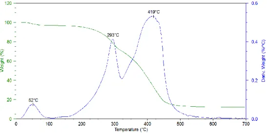
From the TGA analysis showed in Figure 23, it appears that the thermal degradation of the PAA sample is quite complex and occurs through a series of weight loss steps. The peak centred at Tmax of 37°C is ascribable to the loss of water, while it is not clear the
meaning of the other peaks, except for the one centred at Tmax of 216°C. Indeed, the TGA
analysis coupled to FT-IR analysis, that were conducted on the sample at the Department of Industrial Chemistry “Toso Montanari” in Bologna, showed that the first degradation step of PAA represents a decarboxylation process, typical of thermal degradation of a
30
carboxylic acid (results not shown). It is worth to point out that the material starts losing weight right after 130°C, i.e. at a very low temperature.
Figure 23. TGA analysis of pure PAA
Results of DSC analysis are shown in Figure 24. DSC curve of plain PAA is almost identical to that relative to the PAA mat (Fig. 16), demonstrating that the electrospinning process did not modify the polymer thermal properties.
Figure 24. DSC analysis of pure PAA
31
4.3.2 Optimization of blend production procedure
In the next step, different trials were performed to find the best blend compositions, and to optimize the procedure for making them. At this purpose, films of blends at different compositions were prepared by film casting technique from solutions containing different ratio of PAA and bPEI.
The first challenge was to prepare stable solutions avoiding the precipitation of the material, and much attempts were made to reach this result. It suddenly appeared clear that the pH plays a critical role in the stabilization of these polyelectrolyte solutions. As already explained (paragraph 1.1.3), changing in pH values lead to changing in deprotonation/protonation degree of weak polyelectrolytes and so, since the pH value chosen to assemble two polyelectrolytes can affect their charge densities, it will govern the process leading to specific assemblies. To better control this parameter, two different solutions were prepared:
- PAA dissolved in EtOH - bPEI dissolved in H2O
bPEI aqueous solution had an initial pH≈11. In order to reach pH=1, HCl 37% was added to this solution. In this pH condition, all of the nitrogen atoms of the polymer are protonated and are no longer able to share their electron lone pair and to create hydrogen bonds with PAA chains. The inability of forming such interactions avoided the formation of hydrogels or precipitates during the preparation of the blend solutions for film casting and electrospinning. Details on blend solutions preparation are reported in the experimental section.
Films at different compositions (90:10 w/w PAA:bPEI, 80:20 w/w PAA:bPEI, 50:50 w/w PAA:bPEI) of the two polyelectrolytes were produced and exposed to thermal treatment to promote crosslinking and make the material stable in aqueous solutions. Two different thermal treatments were performed: (i) treatment in an oven at 130°C for 24h, and (ii) treatment in an oven at 100°C for 24h. This latter heating at 100°C was made in order to find the lower efficient temperature to promote crosslinking. Experimental assays led to the exclusion of the 50:50 PAA:bPEI blend composition: in fact the obtained film resulted irregular and inhomogeneous and did not respond efficiently to the crosslinking thermal treatments. Therefore only 80:20 and 90:10 PAA:bPEI blend compositions were further investigated.
32
4.3.2.1 80:20 PAA:bPEI film
80:20 PAA:bPEI films were produced as already described, mixing an ethanol PAA solution and an aqueous bPEI solution previously acidified at pH=1, in the proper ratio. At this composition, the ratio between carboxylic groups and primary amines, calculated on the basis of polymer molecular weight and chemical structure, is 3,45: it means that there is an excess of carboxylic groups in the blend. In this calculation, only primary amines of the repeating unity of bPEI were considered, because it was assumed that they would react preferentially in the crosslinking reaction.
The obtained film had a thickness of 110 µm and its TGA curve was compared with the one of PAA powder, and plain bPEI. Figure 25 shows that degradation process of the blend (green curve) is very similar to the one of PAA in powder (blue), but a bit shifted at lower temperatures: the small differences might be attributed to the presence of bPEI.
Figure 25. Overlay of TGA curves of: film 80:20 PAA:bPEI (green); pure bPEI (red); pure PAA (blue)
Thermal treatment seemed the best way to crosslink the system, so the film was put in an oven at both 100°C and 130°C for 24 hours. In this way, it was possible to study how the material reacts to thermal treatments at two different temperatures. The expectation was that the treatment at 130°C would have worked better, producing a film with higher degree of crosslinking than the one treated at 100°C.
33
TGA analysis were carried out on the crosslinked blend, but it was not useful to say which thermal treatment was the better one. In fact, the overlay of the curves (Fig. 26) of a 80:20 PAA:bPEI film not treated (green), heated at 100°C for 24 hours (blue) and heated at 130°C for 24 hours (red) shows how similar the three curves are, and this means that crosslinking does not affect the thermal degradation mechanism significantly.
Figure 26. Overlay of TGA curves of: film 80:20 PAA:bPEI (green); film 80:20 PAA:bPEI after 24h at
130°C (red); film 80:20 PAA:bPEI after 24h at 100°C (blue)
To investigate the efficiency of the two different thermal treatments and the stability in water of the 80:20 PAA:bPEI film crosslinked at 100°C and at 130°C, experiments to assess the gel content and the swelling degree were conducted.
However, it was not possible to evaluate gel content and swelling measurements on the film heated at 100°C for 24 hours: in fact, after an immersion in water for 24 hours, the sample broke and it resulted impossible to collect it and to perform the test.
As already explained, it was possible to determine gel content and swelling tests only on the film heated at 130°C for 24 hours, and the results are showed in Table 4.3.
Table 4.3. Gel content-Swelling degree results for 80:20 PAA:bPEI film heated at 130°C for 24h
Gel Content [%] Swelling degree Film 80:20 treated at 130° for 24h (95 ± 4) (95 ± 4) (6 ± 0.25) (6 ± 0.25)
34
The thermal treatment at 130°C for 24 hours generated a film with a high crosslinking degree with respect to a thermal treated film of only PAA, which dissolved immediately in water.
4.3.2.2 90:10 PAA:bPEI film
Films of 90:10 w/w PAA:bPEI were prepared in the same way as the 80:20 blend, mixing an ethanol PAA solution and an aqueous bPEI solution at pH=1 at the right concentrations and had a width of 85 µm . At this composition, the ratio between carboxylic groups and primary amines is 7,63: it means that, also in this case, there is an excess of carboxylic groups.
TGA analysis, reported in Figure 27, was carried out and it showed that the material starts its degradation process at a temperature of about 170°C and that its degradation mechanism is, as for the 80:20 PAA:bPEI film, similar to the one of the PAA powder.
Figure 27. Overlay of TGA curves of: film 90:10 PAA:bPEI (red); pure bPEI (green); pure PAA (blue)
Two different parts of the 90:10 PAA:bPEI film were then heated in an oven at 100°C and 130°C for 24 hours. The purpose was to investigate how the material reacts to these different treatments and to see if the crosslinking reaction takes place even with heating at 100°C.
35
As the former blend described, the one at 90:10 composition of PAA and bPEI produced a film with interesting behaviour: the film that did not undergo to thermal treatment did not dissolve in water but loosed his transparency, becoming opaque. The part processed in oven did not solve in water and maintained its morphology and transparency.
TGA analysis (Fig. 29) did not show any differences in the degradation behaviour of the film with and without thermal treatment. It is possible to see that, as expected, in the films thermally treated, the weight loss due to the presence of water disappears.
Figure 29. Overlay of TGA curves of: film 90:10 PAA:bPEI (red); film 90:10 PAA:bPEI after 24h at
130°C (blue); film 90:10 PAA:bPEI after 24h at 100°C (green) (c) (b)
Figure 28. (a) 90:10 PAA:bPEI film: (b) thermally treated and exposed to solubility test; (c) not thermally
treated and exposed to solubility test (a)
36
As the 80:20 PAA:bPEI film, even the 90:10 PAA:bPEI, heated at 100°C was not stable in water after 24 hours of immersion, so it was not possible to perform gel content-swelling measurements, as already explained. Therefore, gel content and content-swelling degree tests were performed only on the 90:10 PAA:bPEI film thermally treated at 130°C for 24 hours (Tab. 4.4).
Table 4.4. Gel content-Swelling degree results for 90:10 PAA:bPEI film heated at 130°C for 24h
Gel Content [%] Swelling degree Film 90:10 treated at 130° for 24h (97 ± 0.7) (6 ± 2.4)
The thermal treatment at 130°C for 24 hours generated a film with a higher crosslinking degree with respect to a thermally treated film of only PAA, which dissolved in water.
FT-IR spectra obtained for the PAA:bPEI films (data not showed) did not present the peak characteristic of amides at ⁓1550 cm-1, and this evidence led to affirm that in films, chemical crosslinking between carboxylic groups of PAA and amine groups did not occur and that the results obtained from gel content-swelling tests concerned physical crosslinking. This strong physical crosslinking is probably attributable to the presence of inter and intramolecular interactions such as hydrogen bonds.
4.3.3 Preparation and characterization of electrospun mats from blends at different compositions of PAA and bPEI
Once ended the studies on the preparation of the blend films, the work proceeded with the production of electrospun mats in the chosen compositions. Electrospun mats are fibrous devices that are extensively investigated in drug delivery applications.
The mats were produced through electrospinning starting from solutions at different compositions of PAA and bPEI. As explained for the films, also the mats had to be subjected to thermal treatments at 130° and 100° for 24 hours in order to obtain stability in water.
37
4.2.3.1 80:20 PAA:bPEI mat
Solutions containing PAA and bPEI (80:20 w/w), in a solvent mixture of EtOH and H2O
70:30 were electrospun to produce mats. The process was performed in the conditions described in Paragraph 4.1, and worked well, producing thin fibers without beads. Morphology of the obtained mats was investigated through SEM analysis and results are shown in Figure 30.
Fibers of the mat appear uniform in size and without defects or beads (Fig. 30). Results of the dimensional analysis showed that fibers have a mean diameter of 0.82 µm.
TGA analysis was performed on the mat to see how the material degrades in comparison with the pure components. As shown in Figure 31, curve ascribable to the mat (blue curve) is similar to that of PAA powder, but little modified and shifted to lower temperature probably because of the presence of bPEI (red curve). The analysis showed that the degradation of the mat 80:20 starts right after 92°C.
Std. Deviation: 0.4 Mean: 0.82
Figure 30. SEM images at x1000 (main) and x3000 (inset) of 80:20
38
Figure 31. Overlay of TGA curves of: mat 80:20 PAA:bPEI; PAA powder; pure bPEI.
Two different parts of this mat were then heated in an oven one at 100°C and the other at 130°C, both for 24 hours. This passage is essential for the crosslinking and makes the material insoluble in water. SEM analysis were conducted on the crosslinked mats to see if the thermal treatment generated some modifications on fibers morphology and assembly (Fig. 32).
Figure 32. SEM images at x1000 (main) and x3000 (inset) of 80:20 PAA:bPEI mat after thermal treatment
at 100°C and 130°C for 24h, and relative dimensional analysis
Mean: 0.83 Std. Deviation: 0.3 Mean: 1.07 Std. Deviation: 0.6
39
Results shown in Figure 32 demonstrate that the crosslinking process did not affect the morphology of the fibers, even if the diameter distribution is more broad than the one of fibers before thermal treatment.
Thermal treatment did not affect the degradation mechanism of the mat in a significant way, so 80:20 PAA:bPEI mats not heated, heated at 100°C for 24 hours and heated at 130°C for 24 hours had almost identical TGA curves (data not shown).
An interesting and efficient way to investigate whether crosslinking occurred or not is by FT-IR analysis. In fact, in our system, crosslinking reaction should promote the formation of amide bonds, so that if crosslinking occurs after thermal treatment, we must be able to see peaks relative to amides in the IR spectra.
As shown in Figure 33, the IR spectrum of the mat heated at 130°C presents a peak at 1552 cm-1 (circled in red) that is not observable in the other two spectra. That wavelength is characteristic of peaks ascribable to the bending of N-H bond in an amide. Another difference between the spectra is that, going from the not heated mat to the one heated at 130°C, the relative intensities of the peaks at 3500 cm-1 and at 3000 cm-1 decrease. This change can be explained considering that heating the mat, free amine groups and free hydroxyl groups lower in number probably because they take part in the crosslinking amidation reaction.
Figure 33. IR spectra of 80:20 PAA:bPEI mat not heated (blue), heated at 100°C for 24h (red), heated at
40
In Table 4.5 are reported the assignments of the peaks present in the three IR spectra of Figure 33.
Table 4.5. Peak assignment of IR analysis in Figure 33
Wavelength (cm-1) Functional Group Type of vibration
3553 -N-H2-/-N-H Stretching
3006 -O-H free Stretching
2949-2854 -C-H2- Stretching
1708 -C=O Stretching
1552 N-H (amide) Bending
1449-1405 -C-H2- Bending
1116-1015 -C-N- Stretching
All these considerations lead to say that the thermal treatment at 100°C for 24 hours is not efficient as crosslinking pathway since there is no peak relative to an amide group in the spectrum. Heating the mat at 130°C for 24 hours, instead, bring the system to a good crosslinking degree. This is also demonstrated by gel content-swelling tests: while the test on the mat heated at 130°C proved that after 24 hours of immersion in water, there is still the 99% of the initial mass not dissolved, for the mat heated at 100°C only 78% of the initial mass remained not solved (Tab. 4.6).
Table 4.6. Gel content-Swelling results for 80:20 PAA:bPEI mats heated at 100°C and 130°C for 24h
Generally, higher values of gel content are related to lower values of swelling, but having a look at Table 4.6, it appears clear that the swelling degree is not correlated to the gel content. This finding will be the object of further examinations.
SEM images in Figure 34 shows that the fibrous morphology is destroyed in the mat treated at 100°C and undergone to 24 hours of immersion in water, while in the one heated at 130°C, the immersion in water did not affect the morphology so much. This means that the thermal treatment at 100°C for 24 hours is not so efficient to have a well crosslinked system.
Gel Content [%] Swelling degree Mat 80:20 treated at 100° for 24h (78 ± 1.8) (2 ± 0.1) Mat 80:20 treated at 130° for 24h (99 ± 1.8) (9 ± 0.7)
41
Figure 34. SEM images at x1000 (main) and x4000 (inset) of 80:20 PAA:bPEI mat after thermal treatment
at 100°C (a) and 130°C (b) for 24h, after gel content trials
3.2.3.2 90:10 PAA:bPEI mat
Further mats were produced in the same way as the ones already described, with the only difference that they were made starting from solutions 90:10 PAA:bPEI in composition. The electrospinning process for their production was conducted in the conditions already described, and worked well. Figure 35 shows a SEM micrograph of a 90:10 PAA:bPEI mat not thermally treated. As already explained, this kind of analysis is very useful to see if the fibers are without defects also in a micrometric scale, and if they change their structure and assembly whether they are part of a thermally treated mat or not.
Figure 35. SEM images at x1000 (main) and x3000 (inset) of 90:10 PAA:bPEI mat, and relative
dimensional analysis
Fibers show regular distribution of fibers diameters centred at 0.7 µm.
Mean: 0.70 Std. Deviation: 0.1
42
TGA analysis was performed to characterize the system, but it did not bring out new interesting evidences: the curve, in fact, is almost the same as the curve of the 80:20 PAA:bPEI mat.
Even for this sample, two different thermal treatments were carried out. A part of the mat was heated for 24h in an oven at 100°C, while another part was treated at a temperature of 130°C for 24 hours.
SEM images reported in Figure 36 show how crosslinking process did not affect the morphology of the fibers, that still appeared thin and almost all with the same diameters. Nevertheless, the fiber diameter distribution of the mat heated at 130°C is shifted to higher values of diameters dimensions.
Figure 36. SEM images at x1000 (main) and x3000 (inset) of 90:10 PAA:bPEI mat after thermal treatment
at 100°C and 130°C for 24h, and relative dimensional analysis
Mean: 0.78 Std. Deviation: 0.2
Mean: 0.70 Std. Deviation: 0.3
43
Thermally treated mats appeared slightly more stable regarding their thermal degradation behaviour, than the one not heated. TGA curves (Fig. 37) show how in the latest part of the thermal cycle, at about 450°C, the curve of the not heated mat (green) has a more drastic weight loss, while the heated ones (red and blue) are more stable and lose the same percentage of weight in a wider range of temperature.
There are, instead, not considerable differences between the degradation curves of the two heated mats: this means that thermal treatment efficiency in crosslinking can’t be evaluated via TGA analysis.
Figure 37. Overlay of TGA curves of: mat 90:10 PAA:bPEI (green); mat 90:10 PAA:bPEI after 24h at
100°C (red); mat 90:10 PAA:bPEI after 24h at 130°C (blue)
In Figure 38 (blue curve), FT-IR spectrum of 90:10 PAA:bPEI mat is reported. Compared to a mat of only PAA (Fig. 16), in this spectrum the peak ascribable to the stretching mode of bonded –OH disappears. Only the peak at 3022 cm-1 is attributable to –OH stretching. The sharp shape of this peak lead to think that hydroxyl groups do not form hydrogen bond anymore, but that they all are free. This fact might be due to the presence of the bPEI: this product in fact introduces amine group in the system, that are now the responsible of hydrogen bonds. The shifted position of the peak of the –OH allows to see the peak at 3565 cm-1, ascribable to bPEI amines. In bPEI FT-IR spectrum (Fig. 22), amines peaks are multiples and low in intensity, while here it is possible to see