2018
Publication Year
2021-02-15T12:23:59Z
Acceptance in OA@INAF
AHEAD joint research activity on x-ray optics
Title
Burwitz, Vadim; Willingale, Richard; PARESCHI, Giovanni; Hudec, René; SPIGA,
Daniele; et al.
Authors
10.1117/12.2314109
DOI
http://hdl.handle.net/20.500.12386/30389
Handle
PROCEEDINGS OF SPIE
Series
10699
Number
AHEAD Joint Research Activity on X-ray optics
Vadim Burwitz
1, Richard Willingale
2, Giovanni Pareschi
3, Rene Hudec
4,
Daniele Spiga
3, Carlo Pelliciari
1, Vladimir Tichy
2, Bianca Salmaso
31
MPI für extraterrestrische Physik (MPE), Giessenbachstr., D-85748 Garching, Germany
2Department of Physics and Astronomy, University of Leicester (ULEIC), Leicester LE1 7RH, UK
3INAF/Osservatorio Astronomico di Brera (INAF/OAB), via E. Bianchi 46, 23807 Merate, Lc, Italy
4
Czech Technical University (CTU), Faculty of Electrical Engineering,
Technická 2, 166 27 Praha 6, Czech Republic
ABSTRACT
The progress of X-ray Optics joint research activity of the European Union Horizon 2020 AHEAD project is presented here covering the X-ray optic technologies that are currently being worked on in Europe. These are the Kirkpatrick Baez, lobster eye micropore (SVOM, SMILE), slumped glass, and silicon pore (ATHENA, ARCUS) optics technologies. In this activity detailed comparisons of the measurements, of the different optics produced by the participating optics groups, obtained mainly at the MPEs PANTER X-ray test facility, are compared with simulations. In preparation for the ATHENA mission a study has been made to design the BEaTRiX X-ray test facility for testing individual silicon pore optics mirror modules, and the realization of the facility is now on going. A zone plate collimating optics developed for PANTER is being studied, optimized, and tested at PANTER. This zone plate will be used for characterising a high quality optics module in a parallel beam to verify the BEaTriX performance. Several of the measurements and selected results are presented here.
Keywords: X-ray astronomy, X-ray telescopes, X-ray optics, Silicon Pore Optics, Micro Pore Optics, X-ray testing, ATHENA, Arcus, PANTER X-ray test facility.
1. INTRODUCTION
The integrated Activities for the High Energy Astrophysics Domain AHEAD[1] project is funded as part of the European Union Horizon 2020 program. The overall objective of AHEAD is to integrate national efforts in high-energy Astrophysics and to promote them at the European level, to keep its community at the cutting edge of science and technology and ensure the development of state of the art high-energy astrophysics space observatories.
Within the AHEAD project several Joint Research Activities (JRAs) were setup to:
· Support the technology development for new generation X-ray observatories specifically the § Optics (described in this paper)
§ Sensors
· Support the improvement of the ATHENA[2,3,4,5] baseline technology
· Science prioritization and feasibility studies for gamma-ray instrumentation (~0.1-50 MeV) · Background modelling and cross-calibrations in the context of ATHENA
· Technology Innovation for applications outside the astrophysics domain
The optics joint research activity is divided into the following 3 main fields of study with the associated institutes indicated
· Simulation and testing of prototype X-ray optics for new missions (ULEIC/MPE/INAF-OAB/CTU) · Setup and validation of a XOU screening test facility BEaTriX for ATHENA
(INAF-OAB/MPE in collaboration with IASF/SLAC/ESRF/IMEM-CNR)
· Improved parallel X-ray beam for studying high spatial resolution ATHENA optics at MPEs PANTER X-ray test facility [6,7] (MPE/OAB/ULEIC)
2. SIMULATION AND TESTING OF PROTOTYPE X-RAY OPTICS
This joint research activity concentrates on studying the X-ray optics technologies that are currently being developed in Europe. For the sake of completeness a new promising technology based on silicon that is being developed at NASA is also being studied.
Here is an overview of the X-ray optics technologies that are being studied (see also Figs.1 and 2):
· Silicon Pore Optics (SPO) [8-15] are currently investigated for the development of the ATHENA large collecting area optics with f =12 m. These are developed by ESA & Cosine. These SPOs will also be used and tested for the Arcus [16,17] project.
· Square pore micro-channel plates (MCP) will be investigated for the development of lobster eye modules for wide field X-ray imaging (University of Leicester) here SVOM/MXT[18] and SMILE[19] prototype optics are being tested.
· Slumped Glass Optics (SGO) cold and hot slumped Wolter-I (INAF-OAB / MPE) optics were measured [20] · Kirk-Patrick Baez optics using Silicon plates as an alternative to glass plates are being studied (CTU) [21] three
KB modules were tested at PANTER namely AHEAD KB test module 1D, AHEAD KB test module 2D, and the KB REX module.
· Polished Segmented/Shell Glass Optics High spatial resolution Wolter-I type optics were characterised (INAF-OAB) for the Lynx[22] development [23]
· Polished Segmented Silicon Optics High spatial resolution Wolter-I type optics are being investigated (GSFC) for Star-X / Lynx [22,24,25]
Figure 1. Different X-ray Optical Unit (XOU) technologies (from left to right): Silicon Pore optic, Slumped Glass Optic, Kirkpatrick Baez optic based on glass or silicon plates, Lobster eye based on square pores.
Figure 2. Different grazing incidence optics layouts: (left) Wolter type 1, (center) Kirkpatrick Baez, and (right) lobster eye
3. SIMULATION SOFTWARE AND SIMULATIONS
Simulation software for SPOs and MPOs has been made available to the public on github, a version tracking repository. First measurements of lobster eye micropore optics have been performed at PANTER and are being compared with simulations and the results presented at several SVOM MXT project meetings. The software is now being used for the redesign and optimization of the SPOs for Athena using a smaller maximum aperture size and different overcoating options. An example of SPO simulations are shown in Fig. 3. The full array of ~1000 SPO modules required for the Athena mirror can be simulated including all surface figure errors within the individual modules and the alignment errors for all the modules integrated into the full aperture. The software provides a detailed and comprehensive model of the Athena mirror and is used to provide an accurate prediction of all aspects of the mirror performance, including the PSF,
the effective area as a function of energy, the vignetting function, the defocused PSF and the stray X-ray distribution seen in the focal plane. The MPO simulations are now being applied to the design and optimisation of optics for several missions: SVOM MXT[18] (CNES-CAS) see Fig. 4, Smile[19] (ESA-CAS), Einstein Probe[26] (CAS), Theseus (ESA) and TAO-ISS (NASA). The results from the simulation of lobster eye (both square pore Angel configuration and flat plate Schmidt configuration) are being compared with analytical calculations of the efficiency and collecting area produced by the optics. Fig. 4 shows a comparison between the measured cruciform PSF from a lobster eye optic and the simulation produced by ray tracing. The simulation includes fixed pattern tilt errors of the square pores in the MPO probably resulting from the slumping process used to curve the MPO, shear errors of the pores introduced by the manufacturing process, a random Lorentzian distribution of pore tilt errors which results from the way in which the pores are integrated into the MPO and surface figure and roughness errors on the reflecting walls within the pores produced when the pores are etched and coated with Iridium. The combination of all these is required to provide a close match between the measured and simulated PSF and we can use the model to improve the MPO manufacturing process.
Figure 3. (left) Athena SPO module PSF ray trace, (middle) in-plane errors only, (right) measured X-ray PSF
Figure 4. Measured PSF of an MPO at 1.49 keV (left) X-ray data from Leicester test facility (right). Simulated PSF from ray tracing. The green square indicates the central area of the PSF used for analysis of cross-beam. Blue circle used for analysis of central spot.
4. SETUP AND VALIDATION OF A SILICON PORE OPTIC MIRROR MODULE
SCREENING TEST FACILITY FOR ATHENA
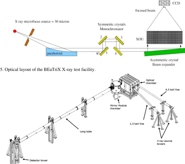
BEaTriX [27] is a new X-ray test facility that will allow a rapid X-ray verification of the SPO mirror modules that will be produced for the ATHENA missions mirror assembly. The current optical design (Fig 5) will allow the production of a parallel (divergence 1.5 arcsec) and uniform X-ray beam of about 170 mm x 60 mm, that is sufficient to fully illuminate the SPO mirror modules (max SPO entrance window is 116.2 mm x 54 mm ). BEaTriX consists of a micro-focus X-ray source (focal spot = 30 mm), a paraboloidal mirror, a monochromation system with symmetrically cut crystals and an asymmetrically-cut crystal for beam expansion. Two beam lines at 4.51 keV and 1.49 keV will be implemented (Fig. 6), with the optical components inside a vacuum system working at 10-3 mbar. The low vacuum level, and the modular vacuum approach will allow the testing of the ATHENA MMs at the production rate of 3 MM/day. The validation of the concept will be done at 4.51 keV, where the crystals are Si (220). In a second phase, the 1.49 keV beam, with the organic ADP (101) crystals, will be implemented. Few modifications, with respect to the previous design have been introduced:
1) the monochromation system was modified from 2 to 4 reflections, including some tilt to reduce the bandwidth of the beam impinging on the beam expander: this is required by the energy dispersive properties of the asymmetrically cut crystals, in order to keep the horizontal divergence within the 1.5 arcsec.
2) the vacuum level was modified from 10-2 to 10-3 mbar, in order to have stable flux of photons also at 1.49 keV 3) a mechanical layout with two fixed beam lines is considered to reduce the risks of misalignment when
switching from one energy to the other.
Figure 5. Optical layout of the BEaTriX X-ray test facility.
BEaTriX will be validated using a “master” SPO MM that has been characterized at PANTER in the parallel beam produced with a zone plate sector. Once the functionality of BEaTriX is verified it can be setup at the industrial site, where the mirror units will be produced.
5. PARALLEL BEAM DEVELOPMENT
The characterisation of high resolution X-ray optics requires a beam divergence of less than 1 arcsec. To date all measurements of X-ray optics are performed at X-ray test facilities such as PANTER which provide slightly divergent beams. Large, homogeneus, X-ray beams with sub-arcsecond divergence are difficult to generate.
Preliminary tests at PANTER show such beam is feasible [28]. This has led to an initial design of a Fresnel zone plate (FZP) sector which generates a 7x7cm2 parallel beam which is currently being implemented at PANTER. An optimization of the material and geometry to improve the efficiency has been performed. A prototype Zone-Plate sector now exists (see Fig. 7). This zone plate will be used for testing the “master optic” that will later be used for verifying the functionality of the BEaTriX Facility.
The FZP has been tested also using the e-Rosita mirror module sector. In that case the HEW of e-ROSITA was too big to see an effective improvement using the FZP compared to the use of the X-ray source focal spot, without any active optics in between. In fact, the e-ROSITA HEW is 50 times bigger then the divergence introduced by the X-ray source spot and the contribution to the final PSF is negligible. In any case was found that the focal length measured using the FZP was in agreement with expected focal position and at correct distance from in focus image position (determined with the thin lense equation) when the optic is in the divergent beam.
To verify the resolving power of the FZP, a multi-pinhole (100 µm pinholes, separated by 1 mm) mask was positioned in front of the source (2.3 m). The FZP was positioned at about 119 m from the X-ray source in order to be able to focus the image of the multi-pinhole mask in the direction of the 14th order. In the resulting image it is possible to distinguish one pinhole from the other, but the pinhole itself. The resulting resolution is 0.5 arcsec. The pinhole cannot be resolved because of the low resolution of the detector and not because of the FZP. The test result has therefore to be considered in a conservative way i.e. FZP generates a parallel beam with a divergence smaller than 0.5 arcsec.
Figure 7. Fresnel Zone Plate Sector (left in image) mounted in the PANTER X-ray test facility. The sector has internal and external radius respectively of 12.5 and 20 cm. The optics was optimized for the AL-Kα line (1.49 keV).
Also, to prove the effectiveness of the diffractive optics, the FZP is going to be used with a very high resolution mirror already characterized in the classical PANTER configuration with an X-ray focal spot size of about 0.6 mm in size (1
arcsec resolution). However, the optics resolution was comparable with the one given by the source. For this reason a further test campaign was performed implementing a 100 µm source. The 100 µm source was obtain mounting a 100 µm pinhole 1.5 m in front of the X-ray source. Then the resulting beam uniformity was checked making a spatial scan using the TRoPIC CCD camera. With such a source the mirror resolution was characterized and confirmed to be close to the arcsecond resolution.
The FZP will then be mounted at about 120 meter from the source (C in Fig. 8). Then the high resolution optics will be mounted in front of the FZP (E), in the 1st order diffracted beam (the parallel one). The detector will acquire the focal image at about 8.4 meter, i.e. the optic focal length (D).
Figure 8: a sketch of the setup that is going to be used to characterize high resolution X-ray optics. At position A it is possible to obtain a detailed image of the X-ray source, B shows the direction of the parallel beam (i.e. the 1st order of the FZP Fresnel zone
plate) and at position D the PSF of the optic E illuminated by the parallel beam can be measured.
To conclude, the FZP will generate a parallel beam with a section of 49 cm2 with a divergence smaller than 0.5 arcsec as required for the characterization of the master SPO to be used for the validation of the BEaTRiX facility.
6. AHEAD RELATED TESTS AT THE PANTER X-RAY TEST FACILITY
Many tests supporting X-ray technologies that are being developed and built for approved missions such as SVOM and missions that are in their early study phases such as ATHENA and ARCUS are ongoing and/or being planned:
Here is a summary of tests at PANTER (see Fig. 9) that have been done in the AHEAD context: § Wolter-I
o SGO and SPO with f=20m performed June/July 2016
o 1st f=12m ARCUS SPO optics tested in May-July 2017 with CAT and OPG gratings o f=8.4m Rib mounted SGO (OAB/GSFC/MPE) tested Aug. 2017
o 1st two f=12m ATHENA SPO [6] optics tested in Nov. 2017 in preparation of ATHENA AIT Tests o two f=12m ATHENA AIT [6,7] (Petals with 2 SPOs) tested in Jan./ Feb. and April 2018
o f=8.4m Polished Silicon Optic (GSFC) performance measured Sept. 2017, Febr. & May 2018 [17] o 1stf=12m confocal SPO MM will be measured in July 2018
§ Kirk-Patrick Baez optics tested successfully in March 2017 [30] o First three f=6.5m 1D Modules, 2 of them in 2D arrangement o REX Payload with two 1D modules in 2D arrangement § Lobster Eye Micro pore optics
o SVOM-BB optics tested at PANTER July 2016
o Next SVOM tests in Autumn 2018, preparations ongoing
Figure 9. The 132m MPI for extraterrestrial Physics PANTER X-ray test Facility, Neuried, Germany
7. SUMMARY
This AHEAD joint research activity on X-ray optics has proven to be very successful so far as that it has nicely fulfilled the objectives it set out to do. On the one side to foster collaboration between different optics groups in Europe through joint measuring campaigns, of development optics as well as optics for upcoming missions, at PANTER and subsequent joint data analysis leading to many publications. On the other side also to be able to work as seed funding for projects (as in this case BEaTRiX) that support new missions. The AHEAD contribution has worked as a catalyst to allow ESA to fund the completion of BEaTRiX facility.
8. ACKNOWLEDGEMENTS
The work presented in this paper was funded mainly by the European Union’s Horizon 2020 Program under the AHEAD project (grant agreement n. 654215).
9. REFERENCES
[1] Natalucci, L. et al., "The AHEAD program for integrating activities in high energy astrophysics", Proc. SPIE 10699, 10699-43 (2018)
[2] Nandra, K. et al., "ATHENA: observing the hot and energetic universe with ESA's next generation x-ray observatory", Proc. SPIE 10699, 10699-48 (2018)
[3] Nandra, P. et al., "ATHENA : The Advanced Telescope for High-Energy Astrophysics", http://www.the-ATHENA-x-ray-observatory.eu/
[4] Ayre, M., et al., "ATHENA: system studies and optics accommodation", Proc. SPIE 10699, 10699-49 (2018) [5] Ayre, M., et al., "ATHENA: system design and implementation for a next-generation x-ray telescope", Proc.
SPIE 10397, 103970X (2017); doi:10.1117/12.2274316
[6] Burwitz V., et al., "In focus measurements of IXO type optics using the new PANTER x-ray test facility extension", Proc. SPIE 8861, 88611J (2013); doi:10.1117/12.2023309
[7] Burwitz, V. , et al., "Testing and calibrating the ATHENA optics at PANTER“, Proc. SPIE 10399, 103990O (2017); doi:10.1117/12.2274237
[9] Bavdaz, M., et al., "The ATHENA telescope and optics status", Proc. SPIE 10399, 103990B (2017); doi: 10.1117/12.2274776
[10] Collon, M. J., et al., "Silicon pore optics mirror module production and testing", Proc. SPIE 10699, 10699-33 (2018)
[11] Collon, M. J., et al., "Development of ATHENA mirror modules", Proc. SPIE 10399, 103990C (2017); doi: 10.1117/12.2273704
[12] Valsecchi, G. et al., "Results of silicon pore optics mirror modules optical integration in the ATHENA telescope", Proc. SPIE 10699, 10699-34 (2018)
[13] Valsecchi, G., et al., "Optical integration of SPO mirror modules in the ATHENA telescope", Proc. SPIE 10399, 103990E (2017); doi:10.1117/12.2272997
[14] Vernani, D. et al., "Integration of the ATHENA mirror modules: development status of the indirect and direct x-ray methods", Proc. SPIE 10699, 10699-35 (2018)
[15] Vernani, D., et al., "Integration of the ATHENA mirror modules: development of indirect and x-ray direct AIT methods", Proc. SPIE 10399, 103990F (2017); doi:10.1117/12.2273829
[16] Ptak, A. F. et al. , "Arcus: the x-ray grating spectrometer explorer", Proc. SPIE 10699, 10699-77 (2018) [17] Smith, R. K., et al., "Arcus: exploring the formation and evolution of clusters, galaxies, and stars", Proc. SPIE
10397, 103970Q (2017); doi:10.1117/12.2272818
[18] Mercier, K. et al. "MXT instrument on-board the French-Chinese SVOM mission", Proc. SPIE 10699, 10699-72 (2018)
[19] Soman, M.R. et al. , " The SMILE Soft X-ray Imager (SXI) CCD design and development", JINST 13 C01022 (2018) ; doi: 10.1088/1748-0221/13/01/C01022
[20] Basso, S. et al., " A hybrid concept (segmented plus monolithic fused silica shells) for a high-throughput and high-angular resolution x-ray mission (Lynx/X-Ray Surveyor like)", Proc. SPIE 10399, 1039911 (2017); doi: 10.1117/12.2275269
[21] Hudec, R. et al., "Kirkpatrick Baez X-ray optics for astrophysics: Recent status", CAOSP 48 (3), 437 (2018) [22] Gaskin, J. A. et al., "The Lynx x-ray observatory: concept study overview and status", Proc. SPIE 10699,
10699-21 (2018)
[23] Civitani, M.M. et al., "The Lynx x-ray observatory: concept study overview and status", Proc. SPIE 10699, 10699-36 (2018)
[24] Zhang, W.W. et al., "The survey and time-domain astrophysical research explorer (STAR-X)", Proc. SPIE 10397, 103970O (2017) ; doi:10.1117/12.2270862
[25] Saha, T.T. et al., "Analysis of the NGXO telescope x-ray Hartmann data", Proc. SPIE 10699, 10699-179 (2018)
[26] Weimin, Y. et al., "Einstein Probe: a lobster-eye telescope for monitoring the x-ray sky", SPIE 10699-76 (2018)
[27] Salmaso, B. et al., "Progress in the realization of the beam expander testing x-ray facility (BEaTriX) for testing ATHENA's SPO modules", Proc. SPIE 10699, 10699-124 (2018)
[28] Menz, B. et. al., "A Fresnel zone plate collimator: potential and aberrations", Proc. SPIE 9603, 96031Q (2015); doi:10.1117/12.2187996
[29] Spiga D., et al., "Optical simulations for design, alignment, and performance prediction of silicon pore optics for the ATHENA x-ray telescope", Proc. SPIE 10399, 103990H (2017); doi:10.1117/12.2274905